DIY two-channel amplifier 50 watts. Powerful amplifier based on the TDA1514A chip (50 W). Tube sound amplifier
The design of this D-class audio amplifier was created for an experiment (I had long wanted to listen and evaluate the new class D), in addition, a new audio amplifier was needed to replace the old one for the computer. It was decided to buy 2 ready-made bridge amplifier modules in class D, which are called TPA3118 (like the microcircuit that is installed in them). They cost 150 rubles each and theoretically produce 60 W mono power. If you wish, you can assemble a similar UMZCH from scratch using separate radio components -.
 TPA3118 module purchased on Ali
 Specifications
- Chip TPA3116
- Operating voltage: 8 - 24 V
- Operating current: up to 7.5 A
- Standby current: 40 mA
- Input level: 0.3 - 6.3 V
- Output power: (12V 4Ohm 25W + 25W) and (21V 4Ohm 50W + 50W)
- Operating frequency: 20 Hz - 20 kHz
- Current and overheat protection
- Board dimensions: 100x60x25 mm
TPA3116 Class D amplifier circuit
 Electrical circuit of the TPA3116 amplifier
 With a unipolar power supply of 12 V, the output power is about 10 W, at 24 V - about 30 W (at 8 Ohm AC).
 Power - ULF distortion, graph
 Judging by the distortion graphs, there’s no need to pump it up too much, up to 20 W and that’s it. Then Kni climbs sharply upward.
 Block board TPA3116, TPA3118, TPA3130
 Despite the modest size of the board and the unusual absence of radiators for an audio assembler, this little guy plays very loudly. The assembly itself took a couple of hours - you don’t need to do anything special, just solder the wires from the connectors and the power supply. But try to do everything as efficiently as possible so that you don’t have to disassemble and redo it later. These UMZCH modules are most often powered by switching power supplies, which whistle and make noise along the circuit. Therefore, install additional capacity filters that will eliminate these effects.


Please note the additional TIP-142 power filter transistor. It was assumed that it would heat up a little, so the transistor was screwed to the body. In reality he is cold. An additional advantage is that the voltage increases gradually through this filter, after switching on for a short time.
In general, for power supply, one more 50V/6800uF capacitor per channel was installed in front of the modules. TPA3116 boards are installed vertically using bushings. If you want the end result to leave a good impression, find a good volume control knob and good audio connections. External power also comes through the socket.
Summary of work and results
The amplifier set on the table near the computer looks very stylish and is convenient in that you can connect different speaker systems to it - it easily drives even 100-watt speakers (of course, not to their full capacity). The voltage is supplied from the laptop power supply 19 V and there is complete silence in the speakers.
I want to build myself a stereo amplifier using two of these microcircuits with a switching power supply. I found out about it from the book “3500 LOW FREQUENCY POWER AMPLIFIER CHICKS...” But I heard that all these chips are TDA 2003; TDA 2004; TDA 2005; 2010...; bad. I already had this happen, I had a TDA 2003 microcircuit lying around, assembled an amplifier on it and it burned out, the microcircuit melted. Maybe someone knows exactly what load the TDA 2025 microcircuit provides a power of 50 watts, since the book says 4 ohms. And here, as I understand it, it writes at 8 ohms. І how many amperes does it need? If anyone assembled it, tell me if it works well, doesn’t the chip burn out right away? Please leave a comment with a video on the internet asking...
Mars 33, about the load:
The load can be either 4 Ohm or 8 Ohm
If you look at the characteristics table, it indicates that the output power will be 45...50 W with a load of 8 Ohms and a voltage of 32 V.
If we talk about TDA microcircuits, then I have only the only microcircuit from this series that burned out immediately - TDA 2005. But, for example, TDA 2030 works perfectly, even with a short circuit. So I can only draw one conclusion, namely, not all TDA are bad. Excellent microcircuits in terms of price/quality ratio.
▼ Show all comments ▼
Have you tried looking for TDA2025 on the Internet?
Look here _http://www.relcomp.ru/products/view/138425
thanks, I'll try to do that)
There is also a cool circuit for a 2-channel 22 W amplifier. There are also a minimum of details and one small thing
Have you tried using the search?!
Amplifier based on TDA1552 chip
can I replace TDA2025 with TDA2025Q? What does the letter “Q” mean?
Lexa777, TDA2025Q can be used. Letter indices may indicate a slight difference in parameters or a difference in the design of the microcircuit housing.
K174UN12 is a two-channel electronic volume and channel balance control.
Connection diagram:
In sound-reproducing equipment they are usually used together.
that is, is tda needed anyway?
For this 50 W amplifier circuit you need exactly TDA2025
By the way, why is there a 0.1 µF capacitor on the sketch of the printed circuit board from plus to minus, in addition to the 100 µF capacitor, although it is not in the circuit diagram?
This ceramic capacitor is placed on the supply terminals to filter out high frequency noise from the power supply. But it is not indicated on the diagram because, in theory, a ceramic capacitor should be an integral part of the power supply of any amplifier.
P.S. And for better filtering of network noise, a ferrite ring is used in addition to the electrolyte and ceramics. This is if the wires from the source are too long.
Thank you for clarifying. Sorry I don't know the basics
We are always happy to help radio amateurs of any level of training. We all started somewhere and still don’t know much.
And at my music center, the weekenders don’t plow. I can’t fix it myself and it’s expensive to carry it for repairs, so I’m thinking of riveting a 2050 on the Tedashka, and the power supply there in the center is also 40V and the acoustics are suitable according to the parameters (ohms and cotton wool). it will be cheap and cheerful—what do you think????????
From time to time I languidly thought that it would be nice to restore the amplifier and put it with speakers to play background music during a feast or sound accompaniment when watching music programs on TV - after all, the wooden speakers, unlike the current plastic ones, sounded, I remember, not bad.
This does not require any special quality, and the Vega AAA class is absolutely useless here. In addition, fiddling with an amplifier for such tasks is completely wasteful.
And my gaze fell on the MP3116mini D-class amplifier offered by Master Kit. It’s too much “All in one”: volume and tone controls, a wide range of unipolar(!) supply voltage, suitable output power of 50 W... The dimensions are absolutely ridiculous: 6 × 3 cm.

Well, I'll try to adapt it to my speakers. A power supply from some laptop with 19 volts and 4 amperes immediately came to hand.
The only negative is the amplifier without a housing. But now I solve such problems using a 3D printer! An irreplaceable thing, I must say, for lovers of the “Do It Yourself” or DIY type, as it is now fashionable to say. I have the modified MC2 on my desk, already like a standard and familiar tool, such as a soldering iron or a screwdriver.
We draw the body in SketchUp and print it, all the fun takes about an hour, well, a little more for painting and drying, since I wanted to have an inconspicuous black body.
I printed it, tried it on, and realized that it would be nice to install a switch and a power indicator. Although the quiescent current of the amplifier is very small, and it can not be turned off at all, but with a switch and indicator it is somehow more familiar.
Conical (step) drills are very helpful in drilling a large diameter hole in a thin body wall. I recommend having these in your home workshop.

The assembled structure looks somehow frivolous in comparison with the speakers. It would have been possible to stuff everything inside the speaker, but I didn’t want to drill through the back wall made of high-quality Soviet plywood.
But believe me, the sound this baby produces is quite up to par! At very low volumes the highs are a little lacking, but this is easily corrected by an equalizer, which is now found in every phone and player from which, in fact, sound is supposed to be played. There are more than enough low ones, we have to turn them down. At medium volume, which is where the main use will be, the sound is quite decent, at high volume it is excellent.
Having bought a good laptop or a cool phone, we rejoice at the purchase, admiring the many functions and speed of the device. But as soon as we connect the gadget to the speakers to listen to music or watch a movie, we understand that the sound produced by the device, as they say, “let us down.” Instead of full and clear sound, we hear an unintelligible whisper with background noise.
But don’t get upset and scold the manufacturers; you can solve the sound problem yourself. If you know a little about microcircuits and know how to solder well, then it will not be difficult for you to make your own audio amplifier. In our article we will tell you how to make a sound amplifier for each type of device.
At the initial stage of creating an amplifier, you need to find tools and buy components. The amplifier circuit is made on a printed circuit board using a soldering iron. To create microcircuits, use special soldering stations that can be bought in the store. The use of a printed circuit board allows you to make the device compact and easy to use.  Audio amplifier
Do not forget about the features of compact single-channel amplifiers based on TDA series microcircuits, the main one of which is the release of a large amount of heat. Therefore, when designing the internal structure of the amplifier, try to prevent the microcircuit from coming into contact with other parts. For additional cooling of the amplifier, it is recommended to use a radiator grille to dissipate heat. The size of the grid depends on the model of the microcircuit and the power of the amplifier. Plan in advance a place for the heat sink in the amplifier case.
Another feature of making your own sound amplifier is low energy consumption. This in turn allows you to use the amplifier in a car by connecting it to a battery or on the road using battery power. Simplified amplifier models require a current voltage of only 3 volts.  Basic amplifier elements
If you are a beginner radio amateur, then for more convenient work, we recommend that you use a special computer program - Sprint Layout. With this program you can independently create and view diagrams on your computer. Please note that creating your own scheme only makes sense if you have sufficient experience and knowledge. If you are an inexperienced radio amateur, then use ready-made and proven circuits.
Below we provide diagrams and descriptions of different sound amplifier options:
Headphone amplifier
The sound amplifier for portable headphones is not very powerful, but consumes very little energy. This is an important factor for mobile amplifiers that are powered by batteries. You can also place a connector on the device for power supply via a 3 volt adapter.  Homemade headphone amplifier
To make a headphone amplifier you will need:
- Chip TDA2822 or analogue KA2209.
- Amplifier assembly diagram.
- Capacitors 100 uF 4 pieces.
- Headphone jack.
- Adapter connector.
- Approximately 30 centimeters of copper wire.
- Heat sink element (for a closed case).
- PCB.
- Chip TDA 7231.
- 9 volt power supply.
- Housing for housing components.
- Non-polar capacitor 0.1 µF - 2 pieces.
- Polar capacitor 100 uF - 1 piece.
- Polar capacitor 220 uF - 1 piece.
- Polar capacitor 470 uF - 1 piece.
- Constant resistor 10 Kom - 1 piece.
- Constant resistor 4.7 Ohm - 1 piece.
- Two-position switch - 1 piece.
- Loudspeaker input jack - 1 piece.
- Input power is 25 watts per channel into 4 ohms and 40 watts per channel into 2 ohms.
- Supply voltage 6-18 volts.
- Reproducible frequency range 20-20000 Hz.
- Simplified installation due to the small number of elements.
- There is no need to sort transistors into complementary pairs.
- 10 watts of power, sufficient for living rooms.
- Good compatibility with new sound cards and players.
- Excellent sound quality.
- Filter capacitors 4 pieces - 2700 rubles.
- Transformer - 2200 rubles.
- Radiators - 1800 rubles.
- Output transistors - 6-8 pieces, 900 rubles.
- Small elements (resistors, capacitors, transistors, diodes) about 2000 rubles.
- Connectors - 600 rubles.
- Plexiglas - 650 rubles.
- Paint - 250 rubles.
- Board, wires, solder about - 1000 rubles
- Class A- amplifiers of this class operate without signal cutoff in the linear portion of the current-voltage characteristic of the amplifying elements, which ensures a minimum of nonlinear distortions. But this comes at the cost of a large amplifier and huge power consumption. The efficiency of a Class A amplifier is only 15-30%. This class includes tube and transistor amplifiers.
- Class B- Class B amplifiers operate with a signal cutoff of 90 degrees. For this mode of operation, a push-pull circuit is used, in which each part amplifies its half of the signal. The main disadvantage of class B amplifiers is signal distortion due to a stepwise transition from one half-wave to another. The advantage of this class of amplifiers is considered to be high efficiency, sometimes reaching 70%. But despite the high performance, you will not find modern class B amplifier models on the shelves.
- Class AB is an attempt to combine amplifiers of the classes described above in order to achieve the absence of signal distortion and high efficiency.
- Class H- designed specifically for cars that have a limitation of the voltage supplying the output stages. The reason for the creation of Class H amplifiers is that the real audio signal is pulsed in nature and its average power is much lower than the peak power. The circuit of this class of amplifiers is based on a simple circuit for a class AB amplifier operating in a bridge circuit. Only a special circuit for doubling the supply voltage has been added. The main element of the doubling circuit is a large-capacity storage capacitor, which is constantly charged from the main power source. At power peaks, this capacitor is connected by the control circuit to the main power supply. The supply voltage to the amplifier's output stage is doubled, allowing it to handle signal peaks. The efficiency of class H amplifiers reaches 80%, with signal distortion of only 0.1%.
- Class D is a separate class of amplifiers called “digital amplifiers”. Digital conversion provides additional sound processing capabilities: from adjusting volume and timbre to implementing digital effects such as reverberation, noise reduction, and acoustic feedback suppression. Unlike analog amplifiers, the output of Class D amplifiers is a square wave. Their amplitude is constant, but their duration varies depending on the amplitude of the analog signal entering the amplifier input. The efficiency of amplifiers of this type can reach 90% -95%.
 Headphone amplifier circuit
The amplifier is manufactured on a printed circuit board or mounted. Do not use a pulse transformer with this type of amplifier as it may cause interference. After manufacturing, this amplifier is capable of providing powerful and pleasant sound from a phone, player or tablet.
You can see another version of a homemade headphone amplifier in the video:
Sound amplifier for laptop
An amplifier for a laptop is assembled in cases where the power of the speakers built into it is not enough for normal listening, or if the speakers are out of order. The amplifier must be designed for external speakers up to 2 watts and winding resistance up to 4 ohms. 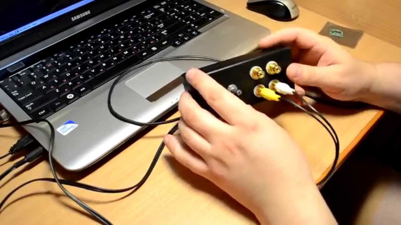 Sound amplifier for laptop
To assemble the amplifier you will need:
 Audio amplifier circuit for laptop
The assembly order is determined independently depending on the diagram. The cooling radiator must be of such a size that the operating temperature inside the amplifier case does not exceed 50 degrees Celsius. If you plan to use the device outdoors, then you need to make a case for it with holes for air circulation. For the case, you can use a plastic container or plastic boxes from old radio equipment.
You can watch the visual instructions in the video:
Sound amplifier for car radio
This amplifier for a car radio is assembled on a TDA8569Q chip; the circuit is not complicated and very common.  Sound amplifier for car radio
The microcircuit has the following declared characteristics:
For use in a car, a filter must be added to the circuit to prevent interference generated by the generator and ignition system. The microcircuit also has protection against output short circuit and overheating.  Audio amplifier circuit for car radio
Referring to the diagram presented, purchase the necessary components. Next, draw the circuit board and drill holes in it. After this, etch the board with ferric chloride. Finally, we tinker and begin to solder the components of the microcircuit. Please note that it is better to cover the power paths with a thicker layer of solder so that there are no power drawdowns.
You need to install a radiator on the chip or organize active cooling using a cooler, otherwise the amplifier will overheat at increased volume.
After assembling the microcircuit, it is necessary to make a power supply filter according to the diagram below:  Interference filter circuit
The choke in the filter is wound in 5 turns, with a wire with a cross-section of 1-1.5 mm, on a ferite ring with a diameter of 20 mm.
This filter can also be used if your radio picks up interference.
Attention! Be careful not to reverse the polarity of the power supply, otherwise the microcircuit will burn out instantly.
You can also learn how to make an amplifier for a stereo signal from the video:
Transistor sound amplifier
As a circuit for a transistor amplifier, use the circuit below:  Transistor audio amplifier circuit
The scheme, although old, has a lot of fans, for the following reasons:
Start assembling the amplifier with the power supply. Separate the two channels for stereo with two secondary windings coming from the same transformer. On the breadboard, make bridges using Schottky diodes for the rectifier. After the bridges there are CRC filters consisting of two 33000 uF capacitors and a 0.75 Ohm resistor between them. A powerful cement resistor is needed for the filter; at a quiescent current of up to 2A, it will dissipate 3 W of heat, so it is better to take it with a margin of 5-10 W. For the remaining resistors in the circuit, a power of 2 W will be enough.  Transistor amplifier
Let's move on to the amplifier board. Everything except the output transistors Tr1/Tr2 is on the board itself. The output transistors are mounted on radiators. It is better to first set up resistors R1, R2 and R6 as trimmers, unsolder them after all adjustments, measure their resistance and solder the final constant resistors with the same resistance. The setting comes down to the following operations - using R6, it is set so that the voltage between X and zero is exactly half of the voltage +V and zero. Then, using R1 and R2, the quiescent current is set - we set the tester to measure direct current and measure the current at the positive input point of the power supply. The quiescent current of an amplifier in class A is maximum and, in fact, in the absence of an input signal, all of it goes into thermal energy. For 8 ohm speakers, this current should be 1.2 A at 27 volts, which means 32.4 watts of heat per channel. Since setting the current can take several minutes, the output transistors should already be on cooling radiators, otherwise they will quickly overheat.
When adjusting and lowering the resistance of the amplifier, the low-frequency cutoff frequency may increase, so for the input capacitor it is better to use not 0.5 µF, but 1 or even 2 µF in a polymer film. It is believed that this circuit is not prone to self-excitation, but just in case, a Zobel circuit is placed between point X and ground: R 10 Ohm + C 0.1 μF. Fuses must be placed both on the transformer and on the power input of the circuit.
It is a good idea to use thermal paste to ensure maximum contact between the transistor and the heatsink.
Now a few words about the case. The size of the case is determined by radiators - NS135-250, 2500 square centimeters for each transistor. The body itself is made of plexiglass or plastic. Having assembled the amplifier, before you start enjoying music, it is necessary to properly distribute the ground to minimize background noise. To do this, connect the SZ to the minus of the input-output, and connect the remaining minuses to the “star” near the filter capacitors.  Transistor audio amplifier housing
Approximate cost of consumables for a transistor audio amplifier:
The resulting amount is 12,100 rubles.
You can also watch a video on assembling an amplifier using germanium transistors:
Tube sound amplifier
The circuit of a simple tube amplifier consists of two stages - a 6N23P pre-amplifier and a 6P14P power amplifier.  Tube amplifier circuit
As can be seen from the diagram, both stages operate in triode connection, and the anode current of the lamps is close to the limit. The currents are adjusted by cathode resistors - 3mA for the input and 50mA for the output lamp.
Parts used for a tube amplifier must be new and of high quality. The permissible deviation of resistor values can be plus or minus 20%, and the capacitances of all capacitors can be increased by 2-3 times.
Filter capacitors must be designed for a voltage of at least 350 volts. The interstage capacitor must also be designed for the same voltage. Transformers for the amplifier can be ordinary - TV31-9 or a more modern analogue - TWSE-6.  Tube sound amplifier
It is better not to install a stereo volume and balance control on the amplifier, since these adjustments can be made in the computer or player itself. The input lamp is selected from - 6N1P, 6N2P, 6N23P, 6N3P. The output pentode is 6P14P, 6P15P, 6P18P or 6P43P (with increased cathode resistor resistance).
Even if you have a working transformer, it is better to use a regular transformer with a 40-60 watt rectifier to turn on the claw amplifier for the first time. Only after successful testing and tuning of the amplifier can the pulse transformer be installed.
Use standard sockets for plugs and cables; to connect speakers, it is better to install 4-pin “pedals”.
The housing for the claw amplifier is usually made from the shell of old equipment or system unit cases.
You can watch another version of a tube amplifier in the video:
Classification of sound amplifiers
So that you can determine which class of sound amplifiers the device you assembled belongs to, read the UMZCH classification below:
 Class A amplifier
  Class B amplifier
  Class AB amplifier
  Class H amplifier
  Class D amplifier
 In conclusion, I would like to say that working in radio electronics requires a large amount of knowledge and experience, which is acquired over a long time. Therefore, if something doesn’t work out for you, don’t be discouraged, reinforce your knowledge from other sources and try again!
When building a high-quality ULF, many choose the well-proven specialized LM3886 chip - a high-quality audio power amplifier capable of delivering more than 50 watts of continuous average power into a 4-ohm load and 40 watts into 8 ohms, at 0.1% THD+N, in the frequency range from 20 Hz to 20 kHz. Why LM3886? Its output elements are fully protected from overvoltage, undervoltage, overloads, including instantaneous temperature peaks. Thermal protection works faster than the chip crystal is destroyed. It has an excellent signal-to-noise ratio of over 92 dB, with a low noise level of only 2 µV. It exhibits extremely low THD+N, around 0.03% at rated power in the audio spectrum, and provides excellent linearity.
50 watt audio amplifier circuit
Divider Rf1, Ri determine the gain in this case, gain 22k/1k = 22 (27dB). The Ci 47uF capacitor forms a high-pass filter with a cutoff frequency of 5 Hz.
Amplifier characteristics on LM3886
- Maximum output power: 65 W RMS - 108 W peak
- Total Harmonic Distortion: 0.02% at 50W
- Signal-to-noise ratio: 110 dB at 50 W - 92 dB at 1 W
Another feature of the circuit is the absence of a delay capacitor that is connected to MUTE. Coil L1 contains 15 turns of enameled wire around resistor R7. The wire diameter must be at least 0.5 mm. The entire throttle structure is wrapped in heat-shrink tubing. Capacitor C2 can be electrolytic, but it is better to use non-polar or bipolar.
As a rule, in audio amplifiers, small-sized toroidal transformers are used, but such transformers are expensive and in short supply. The advantage of a toroidal transformer is that they have very low magnetic flux leakage, so they can be housed in the same housing as the amplifier. In this project we use a standard transformer. The characteristics of the transformer should be as follows;
- For 8 Ohm - standard mode: 220/2 x 24 V (with average output) at least 150 W
- For 4 Ohm - standard mode: 220/2 x 18 V (with average output) at least 150 W
The power supply is simple - bridge rectifier and 4 x 10,000uF/50V capacitors. The chip can be installed on a heatsink without insulation for better thermal conductivity, but then it must be insulated from the metal case, which is usually connected to ground.