How to calculate series and parallel connection together. How to Find the Resistance of Series and Parallel Circuits
When solving problems, it is customary to transform the circuit so that it is as simple as possible. For this, apply equivalent transformations. Equivalent transformations are called such transformations of a part of an electric circuit circuit, in which the currents and voltages in its unconverted part remain unchanged.
There are four main types of conductor connection: series, parallel, mixed and bridge.
serial connection
serial connection- this is a connection in which the current strength is the same throughout the circuit. A prime example serial connection is an old Christmas tree garland. There, the bulbs are connected in series, one after the other. Now imagine one bulb burns out, the circuit is broken and the rest of the bulbs go out. The failure of one element leads to the shutdown of all the others, this is a significant disadvantage of a serial connection.
When connected in series, the resistances of the elements are summed up.

Parallel connection
Parallel connection- this is a connection in which the voltage at the ends of the circuit section is the same. Parallel connection is the most common, mainly because all elements are under the same voltage, the current is distributed differently and when one of the elements leaves, all the others continue to work.

When connected in parallel, the equivalent resistance is found as:
In the case of two resistors connected in parallel 
In the case of three resistors connected in parallel:


mixed connection
mixed connection– a connection, which is a combination of serial and parallel connections. To find the equivalent resistance, you need to “fold” the circuit by alternating the transformation of parallel and series sections of the circuit.

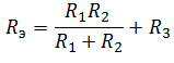
First, we find the equivalent resistance for the parallel section of the circuit, and then add the remaining resistance R 3 to it. It should be understood that after conversion, the equivalent resistance R 1 R 2 and the resistor R 3 are connected in series.
So, the most interesting and most difficult connection of conductors remains.
Bridge circuit
The bridge connection diagram is shown in the figure below.

In order to collapse the bridge circuit, one of the triangles of the bridge is replaced with an equivalent star.

And they find the resistances R 1, R 2 and R 3.
Individual conductors of an electrical circuit can be connected to each other in series, in parallel and mixed. In this case, the series and parallel connection of conductors are the main types of connections, and the mixed connection is their combination.
A series connection of conductors is such a connection when the end of the first conductor is connected to the beginning of the second, the end of the second conductor is connected to the beginning of the third, and so on (Figure 1).
Figure 1. Scheme of serial connection of conductors
The total resistance of a circuit consisting of several series-connected conductors is equal to the sum of the resistances of the individual conductors:
r = r 1 + r 2 + r 3 + … + rn.
Current on separate sections serial circuit is the same everywhere:
I 1 = I 2 = I 3 = I.
Video 1. Serial connection of conductors
Example 1. Figure 2 shows electrical circuit, consisting of three resistors connected in series r 1 = 2 ohm, r 2 = 3 ohm, r 3 = 5 ohm. It is required to determine the readings of voltmeters V 1 , V 2 , V 3 and V 4 if the current in the circuit is 4 A.
Whole circuit resistance
r = r 1 + r 2 + r 3 \u003d 2 + 3 + 5 \u003d 10 ohms.
Figure 2. Scheme for measuring voltages in individual sections of the electrical circuit
In resistance r 1 when current flows, there will be a voltage drop:
U 1 = I × r 1=4×2=8V.
Voltmeter V 1 included between points A And b, will show 8 V.
In resistance r 2 there is also a voltage drop:
U 2 = I × r 2 = 4 × 3 = 12V.
Voltmeter V 2 included between points V And G, will show 12 V.
Voltage drop in resistance r 3:
U 3 = I × r 3 = 4 × 5 = 20 V.
Voltmeter V 3 included between dots d And e, will show 20 V.
If the voltmeter is connected at one end to the point A, the other end to the point G, then it will show the potential difference between these points, equal to the sum of the voltage drops in the resistances r 1 and r 2 (8 + 12 = 20 V).
So the voltmeter V, measuring the voltage at the circuit terminals and connected between the points A And e, will show the potential difference between these points or the sum of the voltage drops in the resistances r 1 , r 2 and r 3 .
This shows that the sum of the voltage drops in individual sections of the electrical circuit is equal to the voltage at the circuit terminals.
Since with a series connection, the circuit current is the same in all sections, the voltage drop is proportional to the resistance of this section.
Example 2 Three resistances of 10, 15 and 20 ohms are connected in series as shown in Figure 3. The current in the circuit is 5 A. Determine the voltage drop across each resistance.
U 1 = I × r 1 = 5 × 10 = 50 V,
U 2 = I × r 2 = 5 × 15 = 75 V,
U 3 = I × r 3 = 5 × 20 = 100 V.
Figure 3. Example 2
The total voltage of the circuit is equal to the sum of the voltage drops in the individual sections of the circuit:
U = U 1 + U 2 + U 3 = 50 + 75 + 100 = 225 V.
Parallel connection of conductors
A parallel connection of conductors is such a connection when the beginnings of all conductors are connected to one point, and the ends of the conductors to another point (Figure 4). The beginning of the circuit is connected to one pole of the voltage source, and the end of the circuit is connected to the other pole.
The figure shows that when the conductors are connected in parallel, there are several ways for the passage of current. Current flowing to the branch point A, spreads further over three resistances and is equal to the sum of the currents leaving this point:
I = I 1 + I 2 + I 3 .
If the currents coming to the branching point are considered positive, and the outgoing currents are negative, then for the branching point we can write:
that is, the algebraic sum of the currents for any nodal point of the circuit is always zero. This relation, which connects the currents at any branching point in the circuit, is called Kirchhoff's first law. The definition of the first Kirchhoff's law can sound in another formulation, namely: the sum of the currents flowing into the node of the electrical circuit is equal to the sum of the currents flowing from this node.
Video 2. Kirchhoff's first law
Usually, when calculating electrical circuits, the direction of currents in the branches connected to any branching point is unknown. Therefore, in order to be able to record the equation of the first Kirchhoff law, it is necessary to arbitrarily choose the so-called positive directions of currents in all its branches before starting the calculation of the circuit and designate them with arrows in the diagram.
Using Ohm's law, you can derive a formula for calculating the total resistance when consumers are connected in parallel.
Total current coming to the point A, is equal to:
The currents in each of the branches have the following values:
According to the formula of Kirchhoff's first law
I = I 1 + I 2 + I 3
![]()
![]()
Bringing out U on the right side of the equation outside the brackets, we get:
![]()
![]()
Reducing both sides of the equality by U, we get the formula for calculating the total conductivity:
g \u003d g 1 + g 2 + g 3.
Thus, with a parallel connection, it is not the resistance that increases, but the conductivity.
Example 3 Determine the total resistance of three resistors connected in parallel if r 1 = 2 ohm, r 2 = 3 ohm, r 3 = 4 ohms.
![]()
![]()
Example 4 Five resistances 20, 30, 15, 40 and 60 ohms are connected in parallel in the network. Determine the total resistance:
![]()
![]()
It should be noted that when calculating the total branching resistance, it always turns out to be less than the smallest resistance included in the branching.
If the resistances connected in parallel are equal to each other, then the total resistance r circuit is equal to the resistance of one branch r 1 divided by the number of branches n:
Example 5 Determine the total resistance of four parallel-connected resistances of 20 ohms each:
![]()
![]()
To check, let's try to find the branching resistance using the formula:
As you can see, the answer is the same.
Example 6 Let it be required to determine the currents in each branch with their parallel connection, shown in Figure 5, A.
Find the total resistance of the circuit:
![]()
![]()
Now we can depict all branches in a simplified way as one resistance (Figure 5, b).
Voltage drop in the section between points A And B will:
U = I × r= 22 × 1.09 = 24 V.
Returning again to Figure 5, we see that all three resistances will be energized at 24 V, since they are connected between the points A And B.
Considering the first branch branch with resistance r 1, we see that the voltage in this section is 24 V, the resistance of the section is 2 ohms. According to Ohm's law for a section of the circuit, the current in this section will be:
![]()
![]()
Current of the second branch
![]()
![]()
Third branch current
![]()
![]()
Let's check according to the first law of Kirchhoff
Good day to all. In the last article, I considered, in relation to electrical circuits containing energy sources. But at the heart of analysis and design electronic circuits along with Ohm's law also lie the laws of balance, called the first Kirchhoff's law, and the voltage balance in the circuit sections, called the second Kirchhoff's law, which we will consider in this article. But first, let's find out how energy receivers are connected to each other and what are the relationships between currents, voltages and.
Receivers electrical energy can be connected with three different ways: in series, in parallel or mixed (in series - in parallel). First consider serial way connection, in which the end of one receiver is connected to the beginning of the second receiver, and the end of the second receiver is connected to the beginning of the third, and so on. The figure below shows the series connection of energy receivers with their connection to an energy source.
An example of a series connection of energy receivers.
IN this case the circuit consists of three series receivers of energy with resistance R1, R2, R3 connected to an energy source with U. Flows through the circuit electricity force I, that is, the voltage across each resistance will be equal to the product of the current and the resistance

Thus, the voltage drop across series-connected resistances is proportional to the values of these resistances.
From the above follows the rule of equivalent series resistance, which states that series-connected resistances can be represented as equivalent series resistance the value of which is equal to the sum of series-connected resistances. This dependence is represented by the following relationships

where R is the equivalent series resistance.
Application of serial connection
The main purpose of the series connection of energy receivers is to provide the required voltage less than the voltage of the energy source. One such application is voltage divider and potentiometer.

Voltage divider (left) and potentiometer (right).
As voltage dividers, series-connected resistors are used, in this case R1 and R2, which divide the voltage of the energy source into two parts U1 and U2. Voltages U1 and U2 can be used to operate different energy receivers.
Quite often, an adjustable voltage divider is used, which is used as a variable resistor R. The total resistance, which is divided into two parts using a moving contact, and thus the voltage U2 on the energy receiver can be smoothly changed.
Another way to connect electrical energy receivers is a parallel connection, which is characterized by the fact that several energy receivers are connected to the same nodes of the electrical circuit. An example of such a connection is shown in the figure below.

An example of a parallel connection of energy receivers.
The electrical circuit in the figure consists of three parallel branches with load resistances R1, R2 and R3. The circuit is connected to an energy source with a voltage U, an electric current with a force I flows through the circuit. Thus, a current flows through each branch equal to the ratio of the voltage to the resistance of each branch

Since all branches of the circuit are under the same voltage U, the currents of the energy receivers are inversely proportional to the resistances of these receivers, and therefore the energy receivers connected in parallel can be seen with one energy receiver with the corresponding equivalent resistance, according to the following expressions

Thus, when connected in parallel, the equivalent resistance is always less than the smallest of the parallel connected resistances.
Mixed connection of energy receivers
The most widespread is a mixed connection of electrical energy receivers. This connection is a combination of series and parallel connected elements. There is no general formula for calculating this type of connection, therefore, in each individual case, it is necessary to select sections of the circuit where there is only one type of receiver connection - serial or parallel. Then, using the equivalent resistance formulas, gradually simplify the fate data and ultimately bring them to the simplest form with one resistance, while calculating currents and voltages according to Ohm's law. The figure below shows an example of a mixed connection of energy receivers

An example of a mixed connection of energy receivers.
As an example, we calculate the currents and voltages in all sections of the circuit. First, let's determine the equivalent resistance of the circuit. Let's single out two sections with parallel connection of energy receivers. These are R1||R2 and R3||R4||R5. Then their equivalent resistance will be

As a result, we got a circuit of two series energy receivers R 12 R 345 equivalent resistance and the current flowing through them will be

Then the voltage drop across the sections will be
Then the currents flowing through each energy receiver will be

As I already mentioned, Kirchhoff's laws, together with Ohm's law, are the main ones in the analysis and calculations of electrical circuits. Ohm's law has been discussed in detail in two previous articles, now it's the turn for Kirchhoff's laws. There are only two of them, the first describes the ratio of currents in electrical circuits, and the second describes the ratio of EMF and voltages in the circuit. Let's start with the first one.
Kirchhoff's first law states that the algebraic sum of the currents in a node is zero. This is described by the following expression
where ∑ denotes an algebraic sum.
The word "algebraic" means that the currents must be taken taking into account the sign, that is, the direction of inflow. Thus, all currents that flow into the node are assigned a positive sign, and those that flow out of the node are assigned a negative sign, respectively. The figure below illustrates Kirchhoff's first law

Depiction of Kirchhoff's first law.
The figure shows a node into which current flows from the side of resistance R1, and current flows from the side of resistances R2, R3, R4, respectively, then the current equation for this section of the circuit will look like
Kirchhoff's first law applies not only to nodes, but to any circuit or part of an electrical circuit. For example, when I was talking about the parallel connection of power receivers, where the sum of the currents through R1, R2 and R3 is equal to the flowing current I.
As mentioned above, Kirchhoff's second law determines the relationship between EMF and voltages in a closed circuit and is as follows: the algebraic sum of the EMF in any circuit circuit is equal to the algebraic sum of the voltage drops on the elements of this circuit. Kirchhoff's second law is defined by the following expression
![]()
As an example, consider the following circuit containing some circuit

Diagram illustrating Kirchhoff's second law.
First you need to decide on the direction of bypassing the contour. In principle, you can choose both clockwise and counterclockwise. I will choose the first option, that is, the elements will be considered in the following order E1R1R2R3E2, so the equation according to the second Kirchhoff law will look like this
Kirchhoff's second law applies to more than just circuits. direct current, but also to chains alternating current and non-linear circuits.
In the next article, I will look at the main ways to calculate complex circuits using Ohm's law and Kirchhoff's laws.
Theory is good, but practical application it's just words.
Details Category: Articles Created: 09/06/2017 19:48How to connect several lamps in a dollhouse
When you think about how to make lighting in a dollhouse or roombox, where there is not one, but several lamps, the question arises of how to connect them, network them. There are two types of connection: serial and parallel, which we have heard about since school. We will consider them in this article.
I'll try to make it simple in plain language so that everything is clear even to the most-most humanitarians who are not familiar with electrical intricacies.
Note: in this article we will consider only a circuit with incandescent bulbs. LED lighting is more complex and will be covered in another article.
For understanding, each circuit will be accompanied by a drawing and, next to the drawing, an electrical wiring diagram.
First consider conventions on electrical diagrams.
| Element name | Symbol on the diagram | Image |
| battery / battery | ||
| switch | ||
| the wire | ||
| wire crossing (no connection) | ||
| wire connection (soldering, twisting) | ||
| incandescent lamp | ||
| faulty lamp | ||
| broken lamp | ||
| burning lamp |
As already mentioned, there are two main types of connection: serial and parallel. There is also a third, mixed: series-parallel, combining both. Let's start with sequential, as simpler.
Serial connection
It looks like this.

Light bulbs are arranged one after another, as in a round dance holding hands. According to this principle, old Soviet garlands were made.
Advantages- ease of connection.
Flaws- if at least one bulb burns out, then the whole circuit will not work.

It will be necessary to sort through, check each light bulb to find the faulty one. This can be tedious when in large numbers light bulbs. Also, the bulbs must be of the same type: voltage, power.
With this type of connection, the voltages of the bulbs add up. The voltage is indicated by the letter U, measured in volts V. The voltage of the power supply must be equal to the sum of the voltages of all the bulbs in the circuit.
Example #1: You want to connect 3 1.5V bulbs in a series circuit. The power supply voltage required for the operation of such a circuit is 1.5 + 1.5 + 1.5 \u003d 4.5V.
Ordinary AA batteries voltage 1.5V. To get a voltage of 4.5V from them, they also need to be connected in a series circuit, their voltages will add up.
Read more about how to choose a power source in this article.

Example #2: you want to connect a 6V light bulb to a 12V power source. 6+6=12v. You can connect 2 of these bulbs.
Example #3: you want to connect 2 3V light bulbs in a circuit. 3+3=6V. A 6V power supply is required.
To summarize: serial connection is easy to manufacture, you need bulbs of the same type. Disadvantages: if one bulb fails, all of them do not light up. You can turn the circuit on and off only as a whole.
Based on this, it is advisable to connect no more than 2-3 light bulbs in series to illuminate the dollhouse. For example, in a bra. To connect large quantity light bulbs, you must use a different type of connection - parallel.
Read also related articles:
- Overview of miniature incandescent lamps
- Diodes or incandescent lamps
Parallel connection of light bulbs
This is how the parallel connection of light bulbs looks like.

In this type of connection, all bulbs and the power supply have the same voltage. That is, with a 12v power source, each of the bulbs must also have a voltage of 12V. And the number of bulbs can be different. And if you, for example, have 6V bulbs, then you need to take a 6V power source.

When one bulb fails, the others continue to burn.

Light bulbs can be turned on independently of each other. To do this, each needs to put its own switch.

According to this principle, electrical appliances are connected in our city apartments. All devices have the same voltage of 220V, they can be turned on and off independently of each other, the power of electrical appliances may be different.
Conclusion: with a lot of lamps in a dollhouse, parallel connection is optimal, although it is slightly more complicated than serial.
Consider another type of connection that combines serial and parallel.
Combined connection
An example of a combined connection.

Three series circuits connected in parallel
And here is another option:

Three parallel circuits connected in series.
Sections of such a circuit, connected in series, behave like a serial connection. And parallel sections are like a parallel connection.
Example

With such a scheme, the burnout of one light bulb will disable the entire section connected in series, and the other two serial circuits will remain operational.
Accordingly, sections can be switched on and off independently of each other. To do this, each serial circuit needs to put its own switch.

But you cannot turn on a single light bulb.
With a parallel-series connection, if one light bulb fails, the circuit will behave like this:

And in case of violation in a sequential section, like this:

Example:

There are 6 3V bulbs connected in 3 series circuits of 2 bulbs each. The circuits are in turn connected in parallel. We divide it into 3 consecutive sections and calculate this section.

In the serial section, the voltages of the bulbs add up, 3v + 3V = 6V. Each series circuit has a voltage of 6V. Since the circuits are connected in parallel, their voltage does not add up, which means we need a 6V power supply.
Example

We have 6 bulbs of 6V. Light bulbs are connected in 3 pieces in a parallel circuit, and the circuits, in turn, are connected in series. We divide the system into three parallel circuits.

In one parallel circuit, the voltage for each light bulb is 6V, since the voltage does not add up, then the entire circuit has a voltage of 6V. And the circuits themselves are already connected in series and their voltages are already added. It turns out 6V + 6V = 12V. So, you need a 12V power supply.
Example
For dollhouses, you can use such a mixed connection.
Suppose there is one lamp in each room, all lamps are connected in parallel. But in the lamps themselves different amount light bulbs: in two - one light bulb each, there is a two-arm sconce made of two light bulbs and a three-arm chandelier. In the chandelier and sconce, the bulbs are connected in series.

Each lamp has its own switch. Power supply 12V voltage. Single bulbs connected in parallel must have a voltage of 12V. And for those that are connected in series, the voltage is added to the section of the circuit
. Accordingly, for a sconce section of two bulbs 12V (total voltage) divided by 2 (number of bulbs), we get 6V (voltage of one bulb).
For the chandelier section 12V:3=4V (voltage of one chandelier bulb).
More than three light bulbs in one lamp should not be connected in series.
Now you have learned all the tricks of connecting incandescent bulbs different ways. And, I think that it will not be difficult to make lighting in a dollhouse with many light bulbs, of any complexity. If something else is difficult for you, read the article about the simplest way to make light in a dollhouse, the most basic principles. Good luck!
In the previous abstract, it was found that the current strength in the conductor depends on the voltage at its ends. If the conductors are changed in the experiment, leaving the voltage on them unchanged, then it can be shown that when constant voltage At the ends of a conductor, the current is inversely proportional to its resistance. Combining the dependence of the current strength on voltage and its dependence on the resistance of the conductor, we can write: I = U/R . This law, established experimentally, is called Ohm's law(for a chain section).
Ohm's law for a circuit section: the strength of the current in the conductor is directly proportional to the voltage applied to its ends and inversely proportional to the resistance of the conductor. First of all, the law is always true for solid and liquid metallic conductors. And also for some other substances (usually solid or liquid).
Consumers of electrical energy (light bulbs, resistors, etc.) can be connected to each other in an electrical circuit in different ways. Dva main types of connection of conductors : serial and parallel. And there are also two more connections that are rare: mixed and bridged.

Serial connection of conductors
When connecting conductors in series, the end of one conductor will connect to the beginning of another conductor, and its end to the beginning of the third, and so on. For example, the connection of electric light bulbs in a Christmas tree garland. When the conductors are connected in series, the current passes through all the bulbs. In this case, the same charge passes through the cross section of each conductor per unit time. That is, the charge does not accumulate in any part of the conductor.
Therefore, when connecting conductors in series the current in any part of the circuit is the same:I 1 = I 2 = I .
The total resistance of the series-connected conductors is equal to the sum of their resistances: R1 + R2 = R . Because when the conductors are connected in series, their total length increases. It is greater than the length of each individual conductor, and the resistance of the conductors increases accordingly.
According to Ohm's law, the voltage across each conductor is: U 1 = I* R1 ,U 2 \u003d I * R 2 . In this case, the total stress is U=I( R1+ R2) . Since the current strength in all conductors is the same, and the total resistance is equal to the sum of the resistances of the conductors, then the total voltage on the series-connected conductors is equal to the sum of the voltages on each conductor: U \u003d U 1 + U 2 .
It follows from the above equalities that the series connection of conductors is used if the voltage for which consumers of electrical energy are designed is less than the total voltage in the circuit.
For a series connection of conductors, the laws are valid :
1) the current strength in all conductors is the same; 2) the voltage on the entire connection is equal to the sum of the voltages on the individual conductors; 3) the resistance of the entire connection is equal to the sum of the resistances of the individual conductors.
Parallel connection of conductors
An example parallel connection conductors serve as a connection for consumers of electrical energy in the apartment. So, light bulbs, a kettle, an iron, etc. are switched on in parallel.
With a parallel connection of conductors, all conductors at one end are connected to one point in the circuit. And the other end to another point in the chain. A voltmeter connected to these points will show the voltage on both conductor 1 and conductor 2. In this case, the voltage at the ends of all parallel-connected conductors is the same: U 1 = U 2 = U .
When the conductors are connected in parallel, the electrical circuit forks. Therefore, part of the total charge passes through one conductor, and part - through the other. Therefore, when the conductors are connected in parallel, the current strength in the unbranched part of the circuit is equal to the sum of the current strength in the individual conductors: I= I 1+ I 2 .
According to Ohm's law I \u003d U / R, I 1 \u003d U 1 / R 1, I 2 \u003d U 2 / R 2 . This implies: U / R \u003d U 1 / R 1 + U 2 / R 2, U \u003d U 1 \u003d U 2, 1/R = 1/R 1 + 1/R 2 The reciprocal of the total resistance of parallel-connected conductors is equal to the sum of the reciprocals of the resistance of each conductor.
When conductors are connected in parallel, their total resistance is less than the resistance of each conductor. Indeed, if two conductors with the same resistance are connected in parallel G, then their total resistance is: R = g/2. This is due to the fact that when the conductors are connected in parallel, their cross-sectional area seems to increase. As a result, resistance is reduced.
From the above formulas it is clear why consumers of electrical energy are connected in parallel. They are all designed for a certain identical voltage, which in apartments is 220 V. Knowing the resistance of each consumer, you can calculate the current strength in each of them. As well as the compliance of the total current strength with the maximum permissible current strength.

For a parallel connection of conductors, the laws are valid:
1) the voltage on all conductors is the same; 2) the current strength at the junction of the conductors is equal to the sum of the currents in the individual conductors; 3) the reciprocal of the resistance of the entire connection is equal to the sum of the reciprocals of the resistances of individual conductors.