Draw an electrical circuit diagram online. Programs for drawing electrical circuits
10 Best Free Online Circuit Simulators
The list of free electronic circuit simulation software online is very useful for you. These circuit simulators that I offer do not need to be downloaded on a computer and can be run directly from the website.
1. EasyEDA electronic circuit design, circuit simulation and PCB design:
EasyEDA is an amazing free online circuit simulator which is very suitable for those who love electronic circuit. EasyEDA team has been committed to making a sophisticated design program on a web platform for several years now, and now the tool is becoming wonderful for the users. The software environment allows you to design the circuit yourself. Check the operation through the circuit simulator. When you make sure the circuit function is good, you will create the PCB with the same software. There are over 70,000+ diagrams available in their web databases along with 15,000+ Pspice library programs. On the site you can find and use many designs and electronic circuits made by others because they are public and open source hardware. It has some pretty impressive import (and export) options. For example, you can import files into Eagle, Kikad, LTspice and Altium designer, and export files as .PNG or .SVG. There are many examples on the site and useful training programs that make it easy for people to manage.
2. Circuit Sims: This was one of the first web-based open source circuit emulators I tested a few years ago. The developer failed to improve the quality and increase the graphical user interface.
3. DcAcLab has visual and attractive plots, but is limited to circuit simulation. This is definitely a great program for learning and is very easy to use. This makes you see the components as they are made. This will not allow you to design the circuit, but will only allow you to practice.
4. EveryCircuit is an online electronics emulator with well-made graphics. When you log into the online program and it will ask you to create a free account so you can save your designs and have a limited area to draw your diagram. To use it without restrictions, it requires an annual fee of $10. It can be downloaded and used on the Android and iTunes platforms. Components have limited ability to simulate with small minimum parameters. Very easy to use, it has an excellent electronic design system. It allows you to include (embed) simulations in your web pages.
5. DoCircuits: Although it leaves people with a first impression of confusion about the site, but it gives many examples of how the program works, you can see yourself in the video "will start in five minutes." Measurements of electronic circuit parameters will be demonstrated with realistic virtual instruments.
6. PartSim electronic circuit simulator online. He was capable of modeling. You can draw electrical circuits and test them. It's still a new simulator, so there are several components to make the simulation to choose from.
7. 123D Circuits An active program developed by AutoDesk, it allows you to create a circuit, you can see it on a breadboard, use the Arduino platform, simulate an electronic circuit and finally create a PCB. The components will be demonstrated in 3D in their actual form. You can program Arduino directly from this simulation program, (it) is really impressive.
8. TinaCloud This modeling program has advanced features. It allows you to simulate, in addition to conventional mixed-signal and microprocessor circuits, VHDL, SMPS electrical supply and radio frequency circuits. Calculations for electronic modeling are performed directly on the company’s server and allow excellent modeling speed
The times of using drawing boards are long gone; they were replaced by graphic editors, these are special programs for drawing electrical circuits. Among them there are both paid applications and free ones (we will consider the types of licenses below). We are confident that the brief overview we have created will help you choose from a variety of software products the software that is most optimal for the task at hand. Let's start with the free versions.
Free
Before moving on to the description of the programs, we will briefly talk about free licenses, the most common of which are the following:
- Freeware– the application is not limited in functionality and can be used for personal purposes without a commercial component.
- Open Source– an “open source” product, into which you can make changes by adjusting the software to your own tasks. There may be restrictions on commercial use and paid distribution of modifications made.
- GNU GPL– a license that practically does not impose any restrictions on the user.
- Public domain– almost identical to the previous version; copyright protection laws do not apply to this type of license.
- Ad-supported– the application is fully functional and contains advertisements for other products of the developer or other companies.
- Donationware– the product is distributed free of charge, but the developer offers to make donations on a voluntary basis for the further development of the project.
Having gained an understanding of free licenses, you can move on to software distributed under such conditions.
Microsoft Visio
This is an easy-to-use, but at the same time very convenient vector graphics editor with a rich functionality. Despite the fact that the main socialization of the program is the visualization of information from MS Office applications, it can be used to view and print radio circuits.
MS releases three paid versions that differ in functionality and a free version (Viewer), which is integrated into the IE browser and allows you to view files created in the editor. Unfortunately, to edit and create new diagrams you will need to purchase a full-featured product. Note that even in the paid versions, among the basic templates there is no set for fully creating radio circuits, but it is not difficult to find and install.
Disadvantages of the free version:
- The functions of editing and creating diagrams are not available, which significantly reduces interest in this product.
- The program only works with the IE browser, which also creates a lot of inconvenience.
Compass-Electric
This software is an application to the CAD system of the Russian developer ASCON. For its operation, the installation of the KOMPAS-3D environment is required. Since this is a domestic product, it fully supports the GOST standards adopted by Russia, and, accordingly, there are no problems with localization.

The application is intended for designing any types of electrical equipment and creating sets of design documentation for them.
This is paid software, but the developer gives you 60 days to familiarize yourself with the system, during which time there are no restrictions on functionality. On the official website and on the Internet you can find a lot of video materials that allow you to familiarize yourself with the software product in detail.
In the reviews, many users note that the system has a lot of shortcomings that the developer is in no hurry to fix.
Eagle
This software is a comprehensive environment in which you can create both a schematic diagram and a printed circuit board layout for it. That is, place all the necessary elements on the board and perform tracing. Moreover, it can be performed either automatically or manually or by a combination of these two methods.

The basic set of elements does not contain models of domestic radio components, but their templates can be downloaded on the Internet. The application language is English, but localizers allow you to set the Russian language.
The application is paid, but it is free to use with the following functional limitations:
- The size of the mounting plate cannot exceed 10.0 x 8.0 cm.
- When routing, only two layers can be manipulated.
- The editor allows you to work with only one sheet.
Dip Trace
This is not a separate application, but a whole software package that includes:
- Multifunctional editor for developing circuit diagrams.
- Application for creating circuit boards.
- A 3D module that allows you to design housings for devices created in the system.
- A program for creating and editing components.

The free version of the software package, for non-commercial use, has minor restrictions:
- Circuit board no more than 4 layers.
- No more than one thousand pins from components.
The program does not provide Russian localization, but it, as well as a description of all functions of the software product, can be found on the Internet. There are also no problems with the component database; initially there are about 100 thousand of them. On thematic forums you can find component databases created by users, including those for Russian GOST standards.
1-2-3 scheme
This is a completely free application that allows you to equip Hager electrical panels with the equipment of the same name.

Program functionality:
- Selecting a housing for an electrical panel that meets the standards for the degree of protection. The selection is made from the Hager model range.
- Complete with protective and switching modular equipment from the same manufacturer. Please note that the element base contains only models certified in Russia.
- Formation of design documentation (single-line diagram, specification that meets ESKD standards, drawing of appearance).
- Creating markers for electrical switchboard switching devices.
The program is completely localized for the Russian language, its only drawback is that the element base contains only the electrical equipment of the developer company.
Autocad Electrical
An application based on the well-known CAD system Autocad, created for designing electrical circuits and creating technical documentation for them in accordance with ESKD standards.

Initially, the database includes over two thousand components, while their conventional graphic symbols meet current Russian and European standards.
This application is paid, but you have the opportunity to get acquainted with the full functionality of the basic working version within 30 days.
Elf
This software is positioned as an automated workstation (AWS) for electrical designers. The application allows you to quickly and correctly develop almost any drawing for electrical projects linked to the floor plan.
The functionality of the application includes:
- Arrangement of UGO when designing electrical networks laid openly, in pipes or special structures.
- Automatic (from the plan) or rune calculation of the power circuit.
- Drawing up specifications in accordance with current standards.
- Possibility of expanding the element base (UGO).

The free demo version does not allow you to create or edit projects; you can only view or print them.
Kicad
This is a completely free open source software package. This software is positioned as an end-to-end design system. That is, you can develop a circuit diagram, use it to create a circuit board and prepare the documentation necessary for production.

Characteristic features of the system:
- The use of external tracers is allowed for board layout.
- The program has a built-in printed circuit board calculator; elements can be placed on it automatically or manually.
- Upon completion of the tracing, the system generates several technology files (for example, for a photoplotter, drilling machine, etc.). If desired, you can add a company logo to the PCB.
- The system can create layer-by-layer printouts in several popular formats, as well as generate a list of components used in development for order generation.
- It is possible to export drawings and other documents to pdf and dxf formats.
Note that many users note that the system interface is poorly thought out, as well as the fact that in order to master the software, you need to thoroughly study the documentation for the program.
TinyCAD
Another free and open source application that allows you to create circuit diagram drawings and has the functions of a simple vector graphics editor. The basic set contains forty different component libraries.
 TinyCAD - a simple editor for circuit diagrams
 The program does not provide PCB tracing, but it does have the ability to export the netlist to a third-party application. Export is carried out with support for common extensions.
The application only supports English, but thanks to the intuitive menu there will be no problems with mastering it.
Fritzing
Free project development environment based on Arduino. It is possible to create printed circuit boards (the layout must be done manually, since the auto-routing function is frankly weak).

It should be noted that the application is “sharpened” for quickly creating sketches that make it possible to explain the operating principle of the designed device. For serious work, the application has a too small base of elements and a very simplified diagram.
123D Circuits
This is a web application for developing Arduino projects, with the ability to program the device, simulate and analyze its operation. A typical set of elements contains only basic radio components and Arduino modules. If necessary, the user can create new components and add them to the database. It is noteworthy that the developed printed circuit board can be ordered directly from the online service.

In the free version of the service, you cannot create your own projects, but you can view other people’s developments that are in the public domain. For full access to all features, you must subscribe ($12 or $24 per month).
Note that due to its poor functionality, the virtual development environment is of interest only to beginners. Many of those who used the service drew attention to the fact that the simulation results differed from real indicators.
XCircuit
Free multi-platform application (GNU GPL license) for quickly creating circuit diagrams. The functional set is minimal.

The application language is English, the program does not accept Russian characters. You should also pay attention to the atypical menu, which you need to get used to. In addition, contextual hints are displayed on the status bar. The basic set of elements includes UGO of only the main radio components (the user can create his own elements and add them).
CADSTAR Express
This is a demo version of the CAD software of the same name. Functional limitations affected only the number of elements used in the development circuit (up to 50 pieces) and the number of contacts (no more than 300), which is quite sufficient for small amateur radio projects.

The program consists of a central module, which includes several applications that allow you to develop a circuit, create a board for it and prepare a package of technical documentation.
The basic set includes more than 20 thousand components; additional libraries can be downloaded from the developer’s website.
A significant drawback of the system is the lack of support for the Russian language; accordingly, all technical documentation is also presented online in English.
QElectroTech
A simple, convenient and free (FreeWare) application for developing electrical and electronic circuit drawings. The program is a regular editor; no special functions are implemented in it.

The application language is English, but there is a Russian localization for it.
Paid applications
Unlike software distributed under free licenses, commercial programs, as a rule, have much more functionality and are supported by developers. As an example, we will give several such applications.
sPlan
A simple editor program for drawing electrical circuits. The application comes with several component libraries that the user can expand as needed. You can work with several projects simultaneously by opening them in separate tabs.

Drawings made by the program are stored as vector graphics files in its own format with the “spl” extension. Conversion to standard raster image formats is allowed. It is possible to print large diagrams on a regular A4 printer.
The application is not officially released in Russian localization, but there are programs that allow you to Russify the menu and contextual hints.
In addition to the paid version, there are two free implementations: Demo and Viewer. In the first one there is no way to save and print the drawn diagram. The second provides only the function of viewing and printing files in the “spl” format.
Eplan Electric
Multi-module scalable CAD system for developing electrical projects of varying complexity and automating the process of preparing design documentation. This software package is now positioned as a corporate solution, so it will not be of interest to ordinary users, especially if you take into account the cost of the software.

Target 3001
A powerful CAD complex that allows you to develop electrical circuits, trace printed circuit boards, and simulate the operation of electronic devices. The online library of components contains more than 36 thousand different elements. This CAD is widely used in Europe for PCB routing.

The default language is English, it is possible to set the menu in German or French, there is no official Russian localization. Accordingly, all documentation is presented only in English, French or German.
The cost of the simplest basic version is about 70 euros. For this money, tracing of two layers with 400 pins will be available. The cost of the unlimited version is around 3.6 thousand euros.
Micro-Cap
An application for modeling digital, analog and mixed circuits, as well as analyzing their operation. The user can create an electrical circuit in the editor and set parameters for analysis. After this, with one click of the mouse, the system will automatically perform the necessary calculations and display the results for study.

The program allows you to establish the dependence of the parameters (ratings) of elements on temperature conditions, illumination, frequency characteristics, etc. If the circuit contains animated elements, for example, LED indicators, then their state will be displayed correctly, depending on the incoming signals. During modeling, it is possible to “connect” virtual measuring instruments to the circuit, as well as monitor the state of various components of the device.
The cost of the full-featured version is about $4.5 thousand. There is no official Russian localization of the application.
TurboCAD
This CAD platform includes many tools for designing various electrical devices. A set of special functions allows you to solve engineering and design problems of any level of complexity.

Distinctive features are fine-tuning of the interface for the user. Lots of reference books, including in Russian. Despite the lack of official support for the Russian language, there are Russifiers for the platform.
For ordinary users, purchasing a paid version of the program in order to develop electrical circuits for amateur devices will be unprofitable.
Designer Schematic
An application for creating electrical circuits using radioelements produced by Digi-Key. The main feature of this system is that the editor can use mechanical design to build circuits.

Component databases can be checked for compliance at any time and, if necessary, updated directly from the manufacturer’s website.
The system does not have its own tracer, but the netlist can be loaded into a third-party program.
It is possible to import files from popular CAD systems.
The approximate cost of the application is about $300.
EDA (Electronic Design Automation) is software for developing and testing electronic equipment. In the most general sense, Sprint Layout, which is so widespread in the Russian-speaking environment, can be classified as EDA. More well-known (and more complete products) include Eagle, DipTrace and Proteus. But they all have one small drawback - they are paid. Someone might object: the same Eagle, they say, also has a free version, albeit somewhat limited. However, these restrictions sometimes become not so much a hindrance as an irritation, such as the inability to position elements off the board, which makes it difficult to redistribute already located parts. Therefore, let's talk about KiCad - until recently little-known, but now gaining popularity software, somewhat burdened with cross-platform, but at the same time actively developing (the latest stable version was released in October 2014). In a couple of articles I will try to talk about the basic techniques and pitfalls of working with KiСad. As an example, let's take a simple Step-Up converter circuit on.
KiCad Program Overview
The main KiCad window is divided into several blocks
- The main menu where you can create or open a project, archive it in zip or unpack it, specify a text editor for viewing files (for example, a list of elements) and an application for viewing PDF, select a language (currently there are 19 languages in the list, including Russian), read the help and copy full information about the installed version to the clipboard.
- The second block contains (from left to right): creating a new project; creating a project from a template (there are no templates yet, but you can create them yourself; such templates will be added to the “Custom” list); opening an existing project; saving all files, be it a circuit diagram or a printed circuit board; archiving the current project in zip; updating the list of project files.
- The third block contains the actual list of files - everything that has a name that matches the name of the project is displayed here.
- The buttons of the fourth block allow you to navigate between the following editors: Eeschema - editor of electrical circuit diagrams of the device; CvPcb - comparison of component seats (in other words, selection of the body of a particular part); Pcbnew - printed circuit board editor; Gerbview - Gerber file viewer; Bitmap2Component - used to create logo images or to create components from existing images. Calculator - contains utilities such as a stabilizer calculator, tables of recommended track thicknesses for printed circuit boards, resistor color coding tables, etc.
- Finally, the last block displays the actions we performed with the current project (what was opened, what was saved, etc.).
The creation of any device begins with the creation of a new project. Therefore, click on the button “ Start a new project».

Select the folder for the future project, write its name, click “ Save", regardless of the style of my windows, in Windows they will be familiar and familiar.

The project name will appear in the left column and we can finally click on the button Eeschema. An editor like this will open...

And KiCad will happily inform us that a certain file is missing. Everything is fine, it just reminds us that we haven't saved the diagram yet, so a blank sheet has been created. In general, KiCad's twists and turns of logic are sometimes amazing. What’s even funnier is that this miracle is supported not by just anyone, but by CERN themselves.
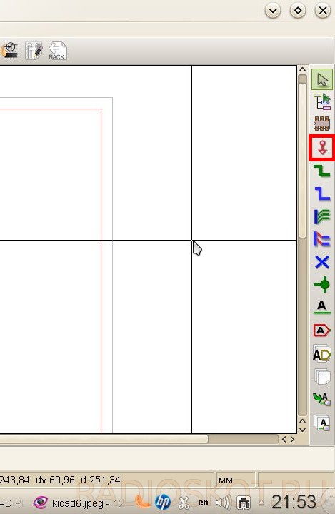
But we digress, let's press OK. In the window that opens, we see the sheet on which our future diagram will be located. Actually, it can be located outside of this sheet, but these parts simply will not be printed. Around the workspace we see a bunch of different buttons; there is no point in explaining the purpose of each of them, because a hint pops up on each of them when you hover (naturally, in Russian). It is worth identifying only the main ones:

Don't be alarmed, everything is not as difficult as it seems at first. As a circuit, as mentioned above, I chose a converter based on MCP34063, also known as MC34063. The diagram is taken from the datasheet:

First of all, let’s look at the menu item “ Settings", where in addition to color settings, appearance parameters (grid pitch, connection thickness, etc.), we are interested in the item " Library" Libraries in KiCad, like in Eagle, contain components used in constructing a circuit. Let's make sure that the files supplied with KiCad are connected and present in the list.


Other libraries can be easily Googled and added via the " Add"(which is quite logical). I also advise you to download component libraries converted from Eagle. However, you should not include all the files at once - this can lead not only to slower loading of the project, but also to annoying messages about duplication of components in libraries. Having dealt with the little things, click on the button “ Place component" in the right panel (or the item " Component" in the menu " Post") and click anywhere on the sheet.


In the window that appears, write in the “Name” field: 34063 - here, unlike Eagle, you do not need to know the exact name of the component, just a part of it is enough.

You can also select a component from the list (button " List of all") or by selecting a suitable symbol (" Select by browsing"). Click OK. If the entered designation appears in several components, we are prompted to select the one we need.

Place the symbol on the sheet.

Attention, rake! KiCad inherited the good tradition of hotkeys from Unix systems. To move a positioned component, it is not enough to simply click on it. You should move the cursor over the component and press the Latin [M] (from English Move) on the keyboard, or right-click on the component and select the corresponding item in the context menu. In the same way, turn with the [R] key and drag (that is, move without breaking away from the chains) with the [G] key. We add a component through the combination, and a conductor through it. The same thing can be done through the context menu. Hotkeys may seem awkward, but in fact most of them are intuitive to a user familiar with English words. In addition, by memorizing a couple of dozen combinations, you can significantly speed up your work. So don’t be lazy and read the certificate, fortunately it has been completely translated into Russian.
Following the microcircuit, we add the remaining components to the sheet. To add passive elements, just write their more or less generally accepted designations (R, C, CP, etc.) in the “Name” field. Once selected, components remain in the “History List” field for quick addition.

To complete adding components, press the key or select the item “ Set aside the tool" To connect the circuits we use " Place Explorer».

It turns out something like this:

If the connection of conductors seems inconvenient (or if the circuit is divided into separate blocks), then it makes sense to use labels. They link separate sections of a chain, just like names in Eagle. KiCad has several types of labels (local, global and hierarchical). Global and hierarchical are used when the blocks of the diagram are located on several sheets and they need to be linked together. The most primitive one is enough for us, so we choose “ Place chain name(local label)".

Click on the desired connection and write the name of the label. At the same time, we select the orientation of the mark - where its connecting point will be located.

Attention, rake! KiCad does not permanently tie the tag to the connection like Eagle does. Once created, a tag can be moved like any other component, but in order for it to be “picked up” by a net, its connecting point must align with a connection on the net or component.

Having placed the necessary marks, we get the following picture:

Now let's add ground and power circuits. They belong to the tool " Place power port»
We write in the search bar “ GND».

Or select the desired component using the button “ List of all»

Having placed the land, we do the same with Vin, selecting the appropriate component. It will have to be connected to a separate conductor. To do this, take the tool “ Place Explorer", click on the desired section of the circuit and pull the conductor to the side. In order to end it not at the connection point, but in an arbitrary place on the sheet, double-click the mouse.

We place the power supply for our circuit. At the output it is enough to simply place a label like “ Vout».

Now let's designate the components and indicate their values. This is done quite simply: you need to hover the cursor over the component and press the [ key V] to assign a denomination and the [ U] to indicate the serial number. However, numbers can also be assigned automatically. To do this, press the button “ Label the components on the diagram»

In the window that appears, configure the notation parameters (you can leave it as is). If parts of the components have already been assigned serial numbers, then you can either continue the current numbering or start it again by first clicking on the button Reset designations».

Having finished with the preparation, click “Design components” and agree with the proposal to give serial numbers to everything. Let's arrange the denominations. Hover the cursor and press [ V]. If several components are in focus, KiCad displays a small menu asking us to specify which component we want to edit.


Finally, check the correctness of the diagram by clicking the “ Perform check...»

In the window that appears, you can configure the verification parameters - the rules for connections between pins (what is considered an error, what is a warning) on the “Parameters” tab.

On the “ERC” tab, click “ ERC test"... and we see error messages.

In this case, green arrow markers will appear on the diagram next to the problem areas. Selecting a line from the list of errors in the ERC window will take us to the corresponding marker. So what is our problem? Here's the thing: it's not enough for KiCad to just put a power port on the circuit; it also needs to indicate that the power port added through the power port is just a power port, and not something else. The apotheosis of crutches, in my opinion, but completely solvable. You just need to pick up the tool again " Place power port» and select the component in the list of ports PWR_FLAG.

The following symbol will appear on the diagram:

PWR_FLAG is displayed only on the diagram and is needed solely to successfully verify its correctness. We connect it to the positive power supply and the GND circuit. We run the ERC test again - there are no more errors.
Attention, rake! When microcircuits with pins that are not connected anywhere are used, the ERC test will swear in their direction. To prevent this from happening, the “Not Connected” flag should be set on all unused pins.
As a result, we ended up with this diagram:

To print it, click on the button on the top panel " Printing the diagram", or select this item in the menu " File».

Attention, rake! Linux users may encounter a problem where a blank sheet is printed instead of a diagram. This happens due to wxWidgets not working correctly with printers.
- a) update wxWidgets to version 3.0;
- b) use the export of the diagram to an accessible graphic format or to a PDF file, and then print it.
It’s not entirely clear what motivated the KiCad developers, but the familiar export is located in the “ Draw».

Here we select the format, adjust the color mode and image quality (default line thickness), and choose whether we need to export the sheet frame along with the diagram. That's probably all you need to know to get started with EESchema. And next time we will talk about the intricacies and creation of new components for libraries. Author of the review - Vetinari.
Discuss the article SOFTWARE FOR DEVELOPING AND TESTING CIRCUITS
Below is a list of the most popular programs for drawing electrical circuits used by radio amateurs.
sPlan
This program allows you to quickly draw various electrical circuits. It is simple and does not require a lot of time to master. The main feature of this program is that there are many add-ons for it containing Russian radio elements.
TyniCad

Eagle
This software has a set of tools that allow you to draw electrical circuits and trace printed circuit boards. It has three modes of operation, which include the ability to develop the circuit yourself or use ready-made elements.

Target 3001
The very name of this program suggests that it stands out from the rest. It supports work even with large circuits and the function of undoing or redoing actions in 50 levels. Another feature of this program is that it supports projects completed in other programs.

DipTrace
The DipTrace program is easy to learn, so it is mainly used by beginners and amateurs to create amateur radio crafts. It includes four modules that allow you not only to create, but also to optimize the layout and size of boards.

KiKad
This program's capabilities include creating professional electrical circuits, designing printed circuit boards for them, and preparing ready-made outputs for final production. This program consists of basic applications and additional utilities that expand the standard functionality.

TyniCad
Even though TinyCAD is an easy-to-learn program, it allows you to design even complex electronic circuits. The developers themselves position TinyCAD as an ordinary application created for drawing and editing diagrams of varying complexity.

Fritzing
This program has a rather narrow focus - Arduino projects. It can be used both to create a sketch and to create a full board. The Fritzing program includes a set of ready-made elements that make it easier to create a board.

123D Circuits
This online service allows you to design electronic circuits and printed circuit boards and supports the Arduino platform. It includes a set of ready-made circuits, but its main feature is the ability to simulate the Arduino platform. This program also supports importing data from Eagle
XCirtuit
This program is classified as an art design program and not an electronic circuit editor. The XCircuit database contains ready-made circuit elements, allowing you to speed up the process of creating an electronic circuit. Having experience allows you to create drawings of average complexity.
Drawing electrical circuits and drawings becomes an easier process if this is done using special software. The programs provide a huge number of tools and functions that are ideal for the task. In this article we have selected a small list of representatives of such software. Let's take a look at them.
First, let's look at the Visio program from the well-known Microsoft company. Its main task is drawing vector graphics, and thanks to this there are no professional restrictions. Electricians can freely create circuits and drawings here using built-in tools.

There are a large number of different figures and objects. Linking them is done with just one click. Microsoft Visio also provides many settings for the appearance of the diagram, page, and supports the insertion of diagram images and additional drawings. A trial version of the program is available for download for free on the official website. We recommend that you familiarize yourself with it before purchasing the complete product.
Eagle
Now let's look at specialized software for electricians. Eagle has built-in libraries containing a large number of different circuit type templates. The new project also begins with the creation of a catalog, where all used objects and documents will be sorted and stored.

The editor is implemented quite conveniently. There is a basic set of tools that help you manually quickly draw the correct drawing. In the second editor, printed circuit boards are created. It differs from the first one in the presence of additional functions that would be incorrect to place in the circuit diagram editor. The Russian language is present, but not all information is translated, which may be a problem for certain users.
Dip Trace
Dip Trace is a collection of several editors and menus that perform various processes on electrical circuits. The transition to one of the available operating modes is carried out through the built-in launcher.

In the mode of working with circuitry, the main actions take place with the printed circuit board. Components are added and edited here. Parts are selected from a specific menu where a large number of objects are installed by default, but the user can create the element manually using a different operating mode.
1-2-3 Diagram
The “1-2-3 Diagram” was developed specifically to select a suitable electrical panel enclosure in accordance with the installed components and the reliability of the protection. The creation of a new scheme occurs through a wizard; the user only needs to select the necessary parameters and enter certain values.

There is a graphical display of the diagram; it can be sent for printing, but cannot be edited. Once the project has been created, the panel cover is selected. At the moment, “1-2-3 Scheme” is not supported by the developer, updates have been coming out for a long time and most likely there will be no more of them at all.
sPlan
sPlan is one of the simplest tools on our list. It provides only the tools and features you need, making the process of creating a diagram as simple as possible. The user only needs to add components, link them and send the board to print, having previously configured it.

In addition, there is a small component editor, useful for those who want to add their own element. Here you can create labels and edit points. When saving an object, you need to be careful that it does not replace the original in the library if it is not necessary.
Compass-3D
"Compass-3D" is professional software for creating various diagrams and drawings. This software not only supports work in a plane, but also allows you to create full-fledged 3D models. The user can save files in a variety of formats and later use them in other programs.

The interface is implemented conveniently and completely Russified, even beginners should quickly get used to it. There are a large number of tools that ensure fast and correct drawing of a diagram. You can download the trial version of Compass-3D on the official website of the developers completely free of charge.
Electrician
Our list ends with “Electrician” - a useful tool for those who often perform various electrical calculations. The program is equipped with more than twenty different formulas and algorithms, with the help of which calculations are carried out in the shortest possible time. The user is only required to fill in certain lines and tick the required parameters.

We have selected several programs for you that allow you to work with electrical circuits. They are all somewhat similar, but also have their own unique functions, thanks to which they become popular among a wide range of users.