Recommendations for overclocking on ASUS ROG Maximus VI motherboards. Recommendations for overclocking on ASUS ROG Maximus VI motherboards Dram ratio fsb 10 2
The BIOS DRAM Ratio utility controls the CPU DRAM ratio. This option is codependent with the and functions. Its configuration is entirely determined by the parameters assigned to the above BIOS options. The following values are available to configure the utility: By SPD, 1:1, 3:2, 3:4, 4:5, 5:4.
The table below shows the correspondence between the parameters of the function in question and the parameters of the other two options.
| DRAM Ratio H/W Strap Value | DRAM Ratio value (CPU DRAM ratio) |
| Low | 1:1, 3:4 |
| High | 1:1, 4:5 |
| N/B Strap CPU As value | |
| PSB800 | 1:1, 3:2, 5:4 |
| PSB533 | 1:1, 4:5 |
| PSB400 | 3:4 |
For advertising purposes, Intel stated that the Pentium 4 CPU model has buses with frequencies of 533, 500 and 800 MHz (MHz). The actual CPU bus frequency is 133, 100 and 200 MHz, respectively. Why such a difference? This fact is explained by the presence of QDR-bus (Quad Data Rate bus) in this CPU model. The speed of information processing on a bus of this type is four times higher than the statistical average. It is the actual numbers that must be taken into account to adjust the CPU DRAM coefficient.
The following tables show the dependence of the effective RAM frequency on the bus frequency and the selected coefficient.
For CPU-bus 100 MHz (equivalent to 400 MHz DDR):
For CPU-bus 133 MHz (equivalent to 533 MHz DDR):
For CPU-bus 200 MHz (equivalent to 800 MHz DDR):
How to use the option?
As a rule, in most cases the By SPD option is used for the utility in question. In this case, the BIOS reads all boot information that is programmed by the developers in a special SPD chip. If manual settings are necessary, do not forget about the 1:1 value as a ratio that is recommended by the manufacturer and allows you to achieve a reasonable balance between RAM speed and its performance.
BIOS menu of the P35 Platinum motherboard. All performance related functions except peripherals, system time, power management are located in the “Cell Menu”. Users who want to adjust the frequency of the processor, memory, or other devices (for example, graphics card bus and south bridge) can use this menu.
Remember that if you are not familiar with BIOS settings, to quickly complete all settings, it is recommended to perform the “Load Optimized Defaults” item, which will ensure normal system operation. Before overclocking, we recommend that users complete this step first and then make fine adjustments.

Cell Menu of P35 Platinum motherboard
All overclocking-related settings are located in the "Cell Menu" section, which includes:- Intel EIST
- Adjust CPU FSB Frequency
- CPU Ratio CMOS Setting (setting the CPU frequency multiplication factor in CMOS)
- Advanced DRAM Configuration (special DRAM configuration)
- FSB/Memory Ratio (FSB/memory frequency ratio)
- PCIEx4 Speed Controller (PCIEx4 speed control)
- Adjust PCIE Frequency
- Auto Disable DIMM/PCI Frequency (automatically disable DIMM/PCI frequency)
- CPU Voltage (CPU supply voltage)
- Memory Voltage
- VTT FSB Voltage
- NB Voltage (Northbridge voltage)
- SB I/O Power (South Bridge I/O Power)
- SB Core Power (South Bridge Core Power)
- Spread Spectrum (clock frequency spectrum limitation)
The user interface of the “Cell Menu” is very simple. Related functions are combined into groups. Users can compare parameter values and make settings step by step.
Before overclocking, please install the functions" D.O.T. Control” and “Intel EIST” to “Disabled” (Default is Enabled). These settings will allow you to set custom values for the processor supply voltage and system bus frequency. After disabling these functions, the option “ CPU Ratio CMOS Setting (setting the processor frequency multiplication factor in CMOS)” .


1. CPU frequency: After loading the optimal settings, this option will automatically show the CPU frequency. For example, for an Intel Core 2 Duo E6850 processor, “333 (MHz)” will be displayed. Frequency setting can be done using the numeric keys or the “Page Up” and “Page Down” keys. When setting, the value displayed in gray “Adjusted CPU Frequency” will change in accordance with the set frequency.

2. CPU frequency multiplier: Depending on the nominal processor frequency, for example, 1333MHz, 1066MHz and 800MHz, the range of multiplier values will be different.

3. Special DRAM configuration: This option is for setting the duration of the memory delay. The smaller its value, the higher the operating speed. However, the limit to its increase depends on the quality of the memory modules.
Advice: If you are using commercially available overclockable memory modules, we recommend that you go to "Cell Menu" > Advanced DRAM Configuration > Configure DRAM Timing by SPD, set this option to Disable, then you will see 9 additional user options that allow you to improve memory performance.

4. FSB/Memory Ratio (ratio of FSB and memory frequencies): This setting determines the relationship between FSB and memory frequencies. When set to “Auto”, the memory frequency will be equal to the processor frequency. When setting a custom value, please follow the 1:1.25 rule. For example, a processor with a frequency of 1333MHz and DDR2-800 memory. Then 1333MHz / 4 x 1.25 x 2 = 833MHz and the DDR2 frequency will be 833MHz.

5. Adjust PCIE Frequency: Typically, PCI Express bus clock speed is not directly related to overclocking; however, fine tuning it can also help with overclocking. (The default value is 100. It is not recommended to set this value above 120 as it may damage the graphics card.)
6. CPU Voltage (CPU supply voltage): This point plays a vital role in overclocking, however, due to the complexity of the relationships, it is not so easy to choose the best setting. We recommend that users perform this setting with caution as an incorrect value may cause processor failure. In our experience, when using a good fan, there is no need to set this value to the limit value. For example, for a Core 2 Duo E6850 processor, it is recommended to set the supply voltage to 1.45~1.5V.
7. Memory Voltage: Since the memory is controlled by the Northbridge, the memory supply voltage should be increased simultaneously with the supply voltage of the main components. Of course, the limit of this increase depends on the quality of the memory modules.
8. VTT FSB Voltage (VTT FSB supply voltage): To ensure that all main components of the system have similar operating voltages, the supply voltage VTT FSB must also be increased. This value should not be too high to avoid unwanted effects.
9. NB Voltage (Northbridge supply voltage): The Northbridge plays a vital role in acceleration. Maintaining the stability of the processor, memory and graphics card can be achieved by increasing this voltage. We recommend that users fine-tune this setting.
10. SB I/O Power: The South Bridge manages the connection of peripheral devices and expansion cards, which play a more important role on new platforms from Intel. The default voltage value for the ICH9R is 1.5V, which determines the I/O voltage setting for peripheral devices. We recommend increasing the voltage to 1.7~1.8V, which will increase the stability of the connection between the North and South bridges, and also help overclocking.
11. SB Core Power (South Bridge Core Voltage): Previously, the Southbridge was ignored during overclocking, however, with increasing supply voltage it improves performance.
It should be remembered that MSI highlights settings in different colors: gray indicates default settings, white indicates safe values, and dangerous values are highlighted in red.

Adviсe: MSI Warns: Check your fan speed frequently. Good cooling plays a decisive role during overclocking.


RAM
When using two memory modules, install them in the red slots (located closer to the processor).
iGPU (integrated graphics core)
The built-in graphics core generates heat during operation. It makes sense that by disabling it you can achieve better overclocking results. Use a PCI-Express video card and disable the function in the BIOS (Disabled) iGPU Multi-Monitor Support to disable the graphics core.
CPU cooling
Use only the best cooling systems because... LGA1150 processors are somewhat hotter than they could be and under heavy loads the protection (Thermal Throttling) may be triggered. When overclocking, it is strictly recommended to use cooling systems that blow air through the radiators on the power subsystem. Or provide them with other fans.
Haswell processors are very temperature sensitive. The better you cool them, the more you can overclock them. It has been experimentally proven that at subzero temperatures, overclocking results are impressive even at reasonable voltages. If you plan to assemble a system, for example, with a freon cooling system, then be sure to take care of insulating the electronic components from condensation. You can check the processor temperature in the CoreTemp utility.
Now you can move on to recommendations for setting up the system in the BIOS.
UEFI BIOS

Maximus VI Extreme comes pre-installed with 5 overclocking profiles. They can become the basis for overclocking your processor instance - you just need to slightly adjust the parameters.
Set the parameter AI Overclock Tuner in meaning Manual to access BCLK control. You can set the X.M.P. mode. to set all the main parameters of RAM in accordance with the characteristics declared by the manufacturer. This mode can also be selected as a basic mode, then its settings can be adjusted.
CPU Strap sets different strap values for the processor. This will allow you to overclock BCLK to the highest possible values for your processor.
The relationship between BCLK, PCIE and DMI frequencies is as follows: PEG Frequency = DMI Controller Frequency = 100 x (BCLK / CPU Strap).
Remember that the working straps may differ for different processors. 
Source Option Clock Tuner will not be available if the value CPU Strap not set to a fixed value.
Parameter PLL Selection can be set to Self Biased Mode (SB-PLL), which will result in better BCLK (base frequency) overclocking, but PCI-E 3.0 performance may deteriorate due to increased PCI-E digital signal jitter. The user can set Inductance/Capacitance Mode (SB-LC) to minimize PCI-E jitter for better compatibility with PCI-E 3.0 devices.
Parameter Filter PLL can be set to mode High BCLK Mode to achieve high BCLK values, but this risks increasing jitter. This mode of operation is usually required to set BCLK above 170 MHz. If you do not need such values, then feel free to set the mode Low BCLK Mode.

ASUS MultiCore Enhancement must be turned on ( Enabled) so that the system automatically raises the processor frequency to the maximum value according to your settings when they exceed the standard values.
Internal PLL Overvoltage must be turned on ( Enabled) for the highest overclocking factor. But also remember that running S3/S4 may make some RAM modules unable to work.
Parameter CPU bus speed: DRAM speed ratio can be set to 100:100 or 100:133. Selecting one of these ratios can be useful for setting the exact RAM frequency. With a DMI/PEG frequency ratio of 1:1, if the DMI/PEG frequency increases by 1%, the memory frequency will also increase by 1%.
Enable Xtreme Tweaking can achieve performance improvements in older benchmarks.

Fully Manual Mode- an exclusive mode from ASUS, thanks to which you can manually adjust six key voltages for the processor. In this mode, the processor will not reduce any of the six voltages while idle, even if EIST or C-States are enabled. If you need energy saving, then you need to turn off this option.

The three most important voltages CPU Core Voltage, CPU Graphics Voltage, CPU Cache Voltage can be set to manual mode ( Manual) to make the options available CPU Core Voltage Override, C PU Graphics Voltage Override And CPU Cache Voltage Override. In this operating mode, the internal voltage regulator supplies precise voltage to the CPU Vcore, CPU Graphics, and CPU Cache. This mode will start working as soon as the Voltage Override values exceed the Auto values. In this mode, voltages will not drop during idle time, even if EIST or C-States are enabled.
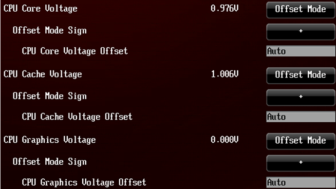
Parameter Offset Mode opens the mode Offset Mode Sign to change voltages CPU Core Voltage Offset, CPU Graphics Voltage Offset And CPU Cache Voltage Offset. To set the voltage offset level, change these parameters. Auto mode is a setting from ASUS professional engineers. If you change the voltage to a minimum step of +-0.001 V, you will get the default voltage.

In mode Adaptive Mode mode will be available Offset Mode and additional mode Additional Turbo Mode Voltage for CPU Vcore, CPU Graphics and CPU Cache. Adaptive mode can be considered an extension of offset mode. Additionally, the set voltage will be active during Turbo Boost operation. Auto mode is a setting from ASUS professional engineers. If you change the voltage to a minimum step of +-0.001 V, you will get the default voltage.

Disabling the feature SVID Support stops interaction between the processor and the external voltage regulator. When overclocking, the recommended value is Disabled.
Separation of voltages into Initial CPU Input Voltage And Eventual CPU Input Voltage allows you to more accurately set the voltages before and after POST. This allows "unsuccessful" processors to POST with a higher voltage and lower it for further operation.
CPU Spread Spectrum need to turn off ( Disabled) when overclocking the processor.
BCLK Recovery must be turned on ( Enabled) when overclocking the processor, so that the system can boot into the BIOS in safe mode if the frequency settings are incorrectly set.

CPU Load-Line Calibration can be set to the maximum level (8) so that the voltage does not sag when the processor is loaded during overclocking. The level can be reduced to reduce power consumption and heat dissipation as long as the system remains stable.
Parameter CPU Voltage Frequency Can be set to "Manual" mode to select a fixed frequency. The higher the frequency, the more stable the input voltage (CPU Input Voltage). Increasing this frequency can give an increase in BCLK overclocking, but it all depends on the processor instance (some may require a lower frequency for b O higher BCLK values). It is highly recommended to enable Enable VRM Spread Spectrum or Enable Active Frequency Mode, if you do not intend to set the processor frequency to a fixed value.
VCCIN MOS Volt Control can be increased to increase stability, but heating will also increase. If you set the value Active VGD, then VCCIN MOS Volt Control will dynamically adjust depending on the processor load.
CPU Power Phase Control must be set to value Extreme so that all phases are active. Otherwise, during idle time, some phases are inactive. This may allow for increased frequency overclocking.
CPU Power Duty Control must be set to value Extreme. This mode prioritizes voltage supply to the iVR rather than balancing with temperature. In this mode you can get a little more overclocking.
CPU Current Capability install 140% to shift the overcurrent protection threshold. This will increase overclocking.
Meaning CPU Power Thermal Control You can increase it if you have problems with power overheating. But it is strongly recommended not to change this parameter. If you have problems due to overheating, then it is better to install additional cooling on the power subsystem radiator.
CPU Input Boot Voltage— the initial voltage from the power subsystem (Extreme Engine DIGI+ III) to the integrated voltage controller (FIVR - Fully Integrated Voltage Regulator), which is used before the BIOS loads. This voltage is active before the Initial CPU Input Voltage set from Extreme Tweaker is applied. Careful selection of this voltage can help achieve the maximum processor frequency.
CPU Current Capability in meaning 130% shifts the overcurrent protection threshold for DRAM VRM. Helps increase RAM overclocking.
DRAM Voltage Frequency V Manual Allows you to manually adjust the VRM frequency. The higher the frequency, the more stable the vDDR voltage, which will allow you to achieve greater memory overclocking (do not forget that overclocking is different for each stick).

DRAM Power Phase Control in meaning Extreme does not allow disconnection of memory power phases. This may allow for increased memory overclocking or increased stability if memory modules are installed in all slots.
Long Duration Packet Power Limit defines the maximum value for throttling when power consumption exceeds a certain level. We can say that this is the first level of protection for the processor from damage. By default, this is the TDP value from Intel. If left in “Auto” mode, it will be set to the value recommended by ASUS experts (OC Expert Team).
Package Power Time Window— a value in seconds that indicates how long the processor is allowed to work above TDP (the value that we set in Long Duration Package Power Limit). The maximum possible value is 127.
Short Duration Package Power Limit indicates the maximum possible power consumption under very short-term loads to avoid system instability. This can be considered the second level of processor protection. Intel considers a normal value of 1.25 from Long Duration Package Power Limit. Although according to the Intel specification for Short Duration Package Power Limit, short-term loads can be no more than 10 ms, ASUS motherboards can withstand much longer.
CPU Integrated VR Current Limit determines the maximum current from the CPU Integrated Voltage Regulator under extremely high loads. The maximum value of 1023.875 essentially disables the iVR's limit removal, which disables throttling due to current exceeding the standard parameters during overclocking.

Frequency Tuning Mode determines the speed of the processor with iVR. Meaning +6% will provide a more stable supply of all six main voltages. Lowering this setting can lower the temperature by several degrees.
Thermal Feedback determines whether the processor will throttle when the external power subsystem overheats. This setting determines whether the power subsystem overheat protection will work. If you disable this protection, it is strongly recommended to monitor the radiator temperature.
CPU Integrated VR Fault Management It is recommended to turn it off if you increase the voltage manually. Disabling it can be useful when overclocking.
CPU Integrated VR Efficiency Management It is recommended to set it to mode High Performance to increase overclocking potential. Balanced mode will bring small energy savings.

Power Decay Mode is responsible for energy saving during idle time. When overclocking, it is recommended to turn off ( Disabled).
Idle Power-in Response Regular. Fast mode is set to reduce power consumption.
Idle Power-out Response When overclocking, it is recommended to set it to mode Fast, which allows the processor to be supplied with a slightly higher voltage with minimal latency.
Parameter Power Current Slope at value LEVEL-4 shifts the throttling time a little further.
Power Current Offset determines the offset of the Power Current Slope parameter. Meaning -100% shifts the CPU throttling time.
Power Fast Ramp Response determines how quickly iVR should respond to voltage requests from the processor. The higher the value, the faster the reaction will be. You can set the value to 1.5 to improve overclocking.
Power Saving Level 1 Threshold determines the minimum power consumption level when the processor should start throttling. Install 0 to disable this feature.
Power Saving Level 2 Threshold- similar to the point above.
Power Saving Level 3 Threshold- similar to the point above.

VCCIN Shadow Voltage— the voltage that is supplied from the external power subsystem to the internal power controller during POST. This voltage is active between CPU Input Voltage and Eventual CPU Input voltage. In Auto mode, the voltage will be set automatically, not above or below safe thresholds.
PLL Termination Voltage (Initial / Reset / Eventual) It is recommended to change it during extreme overclocking at low temperatures. The nominal value is 1.2 V. Safe voltages are up to 1.25 V and above 1.6 V. Do not set the voltage between 1.25 V and the iVR voltage to avoid rapid degradation of the processor.
When overclocking BCLK above 160 MHz, do not forget to set the PLL Termination Reset Voltage and Eventual PLL Termination Voltage to the same level as the Eventual CPU Input Voltage or higher. For example, if Eventual CPU Input Voltage is 1.9 V, then PLL Termination Reset Voltage and Eventual PLL Termination Voltage should be 1.9 V or higher for optimal effect.
If you do not plan to overclock BCLK beyond 160 MHz, then PLL Termination Voltage should be reduced to 1.1 or 1.0 V. Simply put, set this value to 1.25 V or equal to CPU Input Voltage for optimal results.
X-Talk Cancellation Voltage can be increased if the system is unstable (for example, BSOD 0124). But the effect will be the opposite if Max. Vcore Voltage operates under LN2 mode - in this case, reducing the voltage will increase stability. Default is 1.00 V.
Cancellation Drive Strength controls the X-Talk Cancellation Voltage operating mode.
PCH ICC Voltage— voltage to the integrated clock generator. Default is 1.2 V.
For high DMI frequency (>=115 MHz) - try 1.2500 V or lower.
For low DMI frequency (ICC Ringback Canceller can be configured as follows:
-turn on ( Enable) at high DMI frequencies
-turn off ( Disable) at low DMI frequencies
Clock Crossing VBoot- nominal value 1.15000 V. Typically, you need to reduce this voltage to increase acceleration. Lower values may help achieve higher DMI frequencies, but may also reduce PCIe 3.0 stability (raise the value if you encounter PCIe 3.0 instability). Based on experience, the optimal value may be 0.8000 V. Also, increasing this value to 1.65 V may shift the Cold Boot Bug during extreme overclocking (negative temperatures).
Clock Crossing Reset Voltage

Clock Crossing Voltage It is recommended to reduce it to increase acceleration. The default value is 1.15000 V. Reducing this value can help increase the DMI frequency, but at the expense of PCIe 3.0 stability. Based on experience, the optimal value may be 0.8000 V.
DMI De-emphasis Control can be changed manually for better DMI overclocking. But the meaning +6 is optimal.
Parameter SATA Drive Strength can be manually configured to improve SATA stability. The default is 0. You can try changing it in both directions.
CPU PCIE Controller in mode Disabled disables the processor's built-in PCIEx16 controller to improve performance in 2D benchmarks. In this case, only the PCIE_x4_1 slot remains operational.
GEN3 Preset in Auto mode is the optimal value. But you can try all three preset profiles and choose the most productive one. This is especially useful when testing SLI or CrossFireX configurations.
PLX 0.9V Core Voltage / PLX 1.8V AUX Voltage- voltage control on PLX PEX8747 (PCIE 3.0 bridge).
PCIE Clock Amplitude You can configure it manually by selecting the best mode at a high PCIe frequency (due to the high BCLK frequency). More often than not, higher is better.
Internal Graphics(built-in graphics core) it is advisable to disable it to improve overclocking.
This article is a free translation of the official ASUS ROG article.
If you find any inaccuracy, please report it in the official community