DIY LED color music for the home. Do-it-yourself LED color music: working diagrams
Step-by-step assembly of a simple design of LED color music, with an accompanying study of amateur radio programs
Good afternoon, dear radio amateurs!
Welcome to the website ““
We assemble LED light music (color music).
Part 1.
At today's lesson in Beginning radio amateur school we will start collecting LED light music. During this lesson, we will not only assemble light music, but also study another amateur radio program "Cadsoft Eagle"– a simple, but at the same time powerful, comprehensive tool for the development of printed circuit boards and we will learn how to make printed circuit boards using film photoresist. Today we will choose a circuit, look at how it works, and select the details.
Light and music (color and music) devices were very popular during the Soviet Union. They were mainly three-colored (red, green or yellow and blue) and were most often assembled using the simplest circuits on more or less affordable KU202N thyristors (which, if my memory serves me correctly, cost more than 2 rubles in stores, i.e. were quite expensive) and the simplest audio frequency input filters on coils wound on sections of ferrite rods from radio receivers. They were made mainly in two versions - in the form of three-color spotlights on 220-volt light bulbs, or a special case was made in the form of a box, where a certain number of light bulbs of each color were located inside, and the front of the box was closed with frosted glass, which made it possible to obtain a fancy look on such a screen. light accompaniment of music. Also, ordinary glass was used for the screen, and small fragments of car glass were glued on top of it for better light scattering. It was such a difficult childhood. But today, in the age of the development of incomprehensible capitalism in our country, it is possible to assemble a light and sound device for every taste, which is what we will do.
We will take as a basis LED light circuit diagram published on the website:
To this diagram we will add two more elements:
1. . Since we will have a stereo signal at the input, and in order not to lose sound from any channel, or not to connect two channels directly to each other, we will use the following input node (taken from another light-music circuit):

2. Device power supply . We will supplement the light and music circuit with a power supply assembled on a KR142EN8 microcircuit stabilizer:

This is approximately the set of parts we need to assemble:

LEDs for this device can be used of any type, but they must be super-bright and of different colors. I will use ultra-bright, highly directional LEDs, the light from which will be directed towards the ceiling. You, of course, can use a different option for the light display of the sound signal and use a different type of LEDs:

How does this scheme work? . The stereo signal from the sound source is supplied to the input node, which sums the signals from the left and right channels and feeds it to variable resistances R6, R7, R8, which regulate the signal level for each channel. Next, the signal goes to three active filters, assembled according to an identical circuit using transistors VT1-VT3, which differ only in capacitor values. The meaning of these filters is that they pass through only a strictly defined band of the audio signal, cutting off the unnecessary frequency range of the audio signal from above and below. The upper (according to the diagram) filter passes the band 100-800 Hz, the middle one – 500-2000 Hz and the lower one – 1500-5000 Hz. Using trimming resistors R5, R12 and R16, you can shift the transmitted band in any direction. If you want to obtain other signal bandwidths of the filters, you can experiment with the values of the capacitors included in the filters. Next, the signals from the filters are sent to microcircuits A1-A3 - LM3915. What kind of microcircuits are these?
LM3914, LM3915 and LM3916 chips from National Semiconductors allow you to build LED indicators with various characteristics - linear, stretched linear, logarithmic, special for monitoring an audio signal. In this case, LM3914 is for a linear scale, LM3915 is for a logarithmic scale, and LM3916 is for a special scale. We use LM3915 chips - with a logarithmic scale for monitoring the audio signal.
The initial page of the microcircuit datasheet:

(327.0 KiB, 3,977 hits)
In general, I advise you that when faced with a new, unknown radio component, look for its datasheet on the Internet and study it, especially since there are also datasheets translated into Russian.
For example, what we can glean from the first sheet of the LM3915 datasheet (even with minimal knowledge of English, and in extreme cases using a dictionary):
- this microcircuit is an analog signal level indicator with a logarithmic display scale and a step of 3 dB;
– you can connect both LEDs and LCD indicators;
– indication can be carried out in two modes: “dot” and “column”;
– maximum output current for each LED – 30 mA;
- and so on…
By the way, what is the difference between a “dot” and a “column”. In the “dot” mode, when the next LED is turned on, the previous one goes out, and in the “column” mode, the previous LEDs do not go out. To switch to the “point” mode, just disconnect pin 9 of the microcircuit from the “+” power source, or connect it to “ground”. By the way, these microcircuits can be used to assemble very useful and interesting circuits.
Let's continue. Since alternating voltage is supplied to the inputs of the microcircuits, the glowing column of LEDs will have uneven brightness, i.e. As the input signal level increases, not only will successive LEDs light up, but their brightness will also change. Below is a table of the threshold activation of each LED for different microcircuits in volts and decibels:

Characteristics and pinout of transistor KT315:

This concludes the first part of the lesson on assembling LED light music and begins to assemble the parts. In the next part of the lesson, we will study the PCB design program “Cadsoft Eagle” and make a printed circuit board for our device using film photoresist.
We present to you a simple version of the color music installation, which was assembled in an unusual case. Recently we came across scrap metal profiles 20×80 and used them. In the project, it is assembled using 10W LEDs of different colors (green, blue and red).
LED color music scheme
 LED color music circuit 3 channels 10 watts each
 Now the strobe - it is made on the NE555 timer. As for the problem of limiting the LED current, we use the simplest solution, limiting the current through selected resistors. The resistors are bolted to the profile for heat removal and do not overheat at all, operating at a maximum temperature of 60C. The current for each LED was limited to 800 mA.
 LED strobe circuit on NE555 timer
 Device design
Toroidal transformer 14V 50VA. The NE555 strobe along with the IRF540 MOSFET drives two 10W cool white diodes through 5W 1.5 Ohm resistors.
 CMU housing made of aluminum
 All LEDs are mounted on aluminum strips, which are mounted into a common aluminum profile. After 3 hours of testing, the structure remains cold.
 CMU on LEDs with a strobe in the housing
 Set-top box controls
The case was equipped with potentiometers for adjusting levels, a microphone input, a power switch, a fuse, a 220 V network socket and an operating mode switch (strobe-CMU). The entire body is 700 mm long. The effect is very beautiful and powerful. You can easily illuminate a room of at least 200 square meters.
The inexhaustible potential of LEDs has once again been revealed in the design of new and modernization of existing color and music consoles. 30 years ago, color music, assembled from multi-colored 220-volt light bulbs connected to a cassette recorder, was considered the height of fashion. Now the situation has changed and the function of a tape recorder is now performed by any multimedia device, and instead of incandescent lamps, super-bright LEDs or LED strips are installed.
The advantages of LEDs over light bulbs in color music consoles are undeniable:
- wide color gamut and more saturated light;
- various design options (discrete elements, modules, RGB strips, rulers);
- high response speed;
- low power consumption.
How to make color music using a simple electronic circuit and make LEDs blink from an audio frequency source? What options for converting an audio signal are there? Let's look at these and other questions using specific examples.
The simplest circuit with one LED
First you need to understand a simple color music circuit, assembled on one bipolar transistor, resistor and LED. It can be powered from a DC source with a voltage of 6 to 12 volts. This color music works on one transistor according to the principle of an amplification stage with a common emitter. A disturbing influence in the form of a signal with varying frequency and amplitude arrives at the VT1 base. As soon as the oscillation amplitude exceeds a certain threshold value, the transistor opens and the LED flashes.
The disadvantage of this simplest scheme is that the rate of blinking of the LED depends entirely on the level of the sound signal. In other words, a full-fledged color-musical effect will be observed only at one volume level. Lowering the volume will result in a rare wink, while increasing the volume will result in an almost constant glow.
Scheme with single-color LED strip
The simplest color music above on a transistor can be assembled using an LED strip in the load. To do this, you need to increase the supply voltage to 12V, select a transistor with the highest collector current exceeding the load current and recalculate the resistor value. This simple color music from an LED strip is perfect for beginning radio amateurs to assemble with their own hands, even at home.
Simple three-channel circuit
A three-channel audio converter allows you to get rid of the shortcomings of the previous scheme. The simplest scheme of color music with the division of the sound range into three parts is shown in the figure.  It is powered by a constant voltage of 9V and can illuminate one or two LEDs in each channel. The circuit consists of three independent amplifier stages assembled on KT315 (KT3102) transistors, the load of which includes LEDs of different colors. As a pre-amplification element, you can use a small step-down network transformer.
The input signal is fed to the secondary winding of the transformer, which performs two functions: galvanically isolates the two devices and amplifies the sound from the line output. Next, the signal goes to three parallel-connected filters assembled on the basis of RC circuits. Each of them operates in a specific frequency band, which depends on the values of resistors and capacitors. The low-pass filter passes sound vibrations with a frequency of up to 300 Hz, as indicated by the blinking red LED. Sound in the range of 300-6000 Hz passes through the mid-pass filter, which is manifested in the flickering of the blue LED. The high-pass filter passes a signal whose frequency is greater than 6000 Hz, which corresponds to the green LED. Each filter is equipped with a trimming resistor. With their help, you can set the uniform glow of all LEDs, regardless of the musical genre. At the output of the circuit, all three filtered signals are amplified by transistors.
If the circuit is powered from a low-voltage DC source, then the transformer can be safely replaced with a single-stage transistor amplifier.  Firstly, galvanic isolation loses its practical meaning. Secondly, the transformer is several times inferior to the circuit shown in the figure in terms of weight, size and cost. The circuit of a simple audio amplifier consists of a KT3102 transistor, two capacitors that cut off the DC component, and resistors that provide the transistor with a common emitter mode. Using a trimmer resistor, you can achieve overall amplification of a weak input signal.
In the case when it is necessary to amplify the signal from the microphone, an electret microphone is connected to the input of the previous circuit, applying potential to it from the power source. The circuit of a two-stage preamplifier is shown in the figure.  In this case, the trimming resistor is located at the output of the first amplifier stage, which gives more opportunities for adjusting sensitivity. Capacitors C1-C3 pass the useful component and cut off the direct current. Any electret microphone is suitable for implementation; for normal operation, a bias of 1.5 V is sufficient.
Color music with RGB LED strip
The following circuit of a color music console operates on 12 volts and can be installed in a car. It combines the main functions of the previously discussed circuit solutions and is capable of operating in color music and lamp modes.
The first mode is achieved through contactless control of the RGB strip using a microphone, and the second mode is achieved through the simultaneous illumination of red, green and blue LEDs at full power. The mode is selected using a switch located on the board. Now let’s take a closer look at how to make color music that is perfect even for installation in a car, and what parts are required for this.
Block diagram
To understand how this color music console works, let’s first consider its structural diagram. It will help trace the full path of the signal.  The source of the electrical signal is a microphone, which converts sound vibrations from the phonogram. Because This signal is too small and must be amplified using a transistor or operational amplifier. Next comes the automatic level controller (AGC), which keeps the sound fluctuations within reasonable limits and prepares it for further processing. Filters divide the signal into three components, each of which operates only in one frequency range. In the end, all that remains is to amplify the prepared current signal, for which transistors operating in switching mode are used.
Schematic diagram
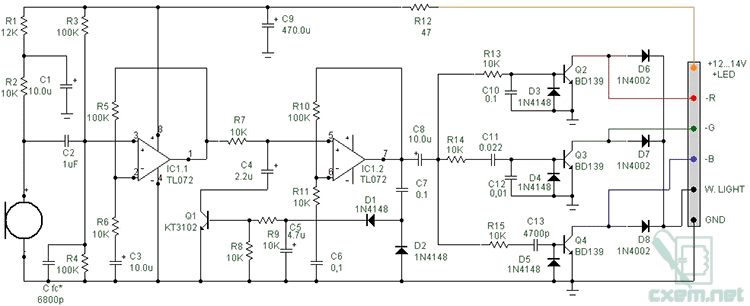
Based on the structural blocks, we can proceed to a consideration of the circuit diagram. Its general appearance is shown in the figure.  To limit current consumption and stabilize the supply voltage, resistor R12 and capacitor C9 are installed. R1, R2, C1 are set to set the microphone bias voltage. Capacitor C fc is selected individually for a specific microphone model during the setup process. It is needed in order to slightly muffle the signal of the frequency that prevails in the microphone’s operation. Usually the influence of the high-frequency component is reduced.
Unstable voltage in the vehicle network can affect the operation of color music. Therefore, it is most correct to connect homemade electronic devices through a 12V stabilizer.
Sound vibrations in the microphone are converted into an electrical signal and, through C2, are supplied to the direct input of the operational amplifier DA1.1. From its output, the signal goes to the input of the operational amplifier DA1.2, equipped with a feedback circuit. The resistances of resistors R5, R6 and R10, R11 set the gain DA1.1, DA1.2 equal to 11. The elements of the OS circuit: VD1, VD2, C4, C5, R8, R9 and VT1, together with DA1.2, are part of the AGC. At the moment a signal of too large an amplitude appears at the output of DA1.2, transistor VT1 opens and, through C4, closes the input signal to the common wire. This results in an instantaneous reduction in the output voltage.
Then the stabilized alternating current of audio frequency passes through the cut-off capacitor C8, after which it is divided into three RC filters: R13, C10 (LF), R14, C11, C12 (MF), R15, C13 (HF). In order for the color music on LEDs to shine brightly enough, you need to increase the output current to the appropriate value. For tape with a consumption of up to 0.5A per channel, medium-power transistors such as KT817 or imported BD139 without mounting on a radiator are suitable. If the do-it-yourself light-music assembly involves a load of about 1A, then the transistors will require forced cooling.
In the collectors of each output transistor (parallel to the output) there are diodes D6-D8, the cathodes of which are connected to each other and connected to switch SA1 (White light). The second contact of the switch is connected to the common wire (GND). While SA1 is open, the circuit operates in color music mode. When the switch contacts are closed, all the LEDs in the strip light up at full brightness, forming a total white stream of light.
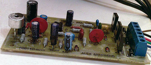
Printed circuit board and assembly parts
To make a printed circuit board, you will need a single-sided PCB measuring 50 by 90 mm and a ready-made .lay file, which can be downloaded. For clarity, the board is shown from the side of the radio elements. Before printing, you must set its mirror image. Layer M1 shows 3 jumpers placed on the parts side.  To assemble color music from an LED strip with your own hands, you will need accessible and inexpensive components. An electret type microphone, suitable in a protective case from old audio equipment. Light music is assembled on a TL072 chip in a DIP8 package. Capacitors, regardless of type, must have a voltage reserve and be designed for 16V or 25V. If necessary, the board design allows you to install output transistors on small radiators. A terminal block with 6 positions is soldered on the edge for supplying power, connecting an RGB LED strip and a switch. A complete list of elements is given in the table.
  In conclusion, I would like to note that the number of output channels in a homemade color music set-top box can be increased as many times as desired. To do this, you need to divide the entire frequency range into a larger number of sectors and recalculate the bandwidth of each RC filter. Connect LEDs of intermediate colors to the outputs of additional amplifiers: violet, turquoise, orange. Do-it-yourself color music will only become more beautiful from such an improvement.
The given diagrams belong to the site cxem.net
Read also
This device is designed to accompany musical soundtracks with lighting effects. A special feature of the device is that it does not have an electrical connection to the sound signal source. The device was developed for use in conjunction with 12 Volt. The idea itself was born when creating LED lighting for a car trunk when opening the lid. But then the thought came about the second function of the trunk light. One click of the microswitch - and the lighting lantern turns into a small color and music spotlight for a picnic in nature. In order not to connect a separate signal cable from the radio to it, it is necessary for the circuit to respond to sound; for this you need a microphone. Separate fragments of the circuit were taken from different sites (including Soldering Iron), collected together, and coordinated with each other.
Let's consider the operation of the device, based on the block diagram:
The signal from the microphone is very weak, so it must first be amplified for further work with it. In the circuit diagram, the microphone amplifier is IC1.1. The microphone voltage amplitude is amplified 11 times. But here the question arises: what if the sound volume is very low or too high, and the amplified signal does not correspond to the level for further processing? To do this, you need some kind of “stabilizer” of the signal level so that, regardless of the volume of the phonogram (within certain limits!), the amplitude of the signal remains unchanged. This signal “stabilizer” is called an automatic level controller (AGC), or compressor. On the principle, this is done by IC1.2 and Q1. The second half of the chip again serves as an 11-fold amplifier, but its output signal is rectified (D1 and D2), and supplied as a bias to the base of Q1. If the signal is too large, Q1 opens, its collector junction resistance decreases, thereby the transistor shunts the excessive signal at the input of IC1.2 coming from R7. Next, we need to decompose our standardized signal into three frequency components so that the red flashes correspond to the drums and bass instruments; vocals, rhythm and lead guitars – green; cymbals and high tones are blue. The red signal is passed through the low-pass filter (R13, C10); green - FSF (R14, C11, C12); blue – high-pass filter (R15, C13). Next are current and voltage amplifiers for each channel, because the energy of these filtered signals is not enough to light the corresponding RGB strip channels.
Schematic diagram of color music:
Now a little about the details. The microphone was an electret one from a destroyed computer headset. You should pay attention to the polarity of the microphone; there is a special bias for it (R1, R2, C1). All electrolytic capacitors must have an operating voltage of at least 16 Volts. The remaining capacitors are ceramic. I want to pay special attention to C fc*. Perhaps there will be no need to install it. With the microphone I used, there was a lot of high frequencies, so I had to “calm them down” a little with this capacitor. Diodes D1...D5 can be replaced with analogues of KD522. If the device will be used only as a CMU, then D6...D8 does not need to be installed. When the microswitch closes the GND and W.LIGHT contacts, the strip works like a regular white cold glow lamp. Transistor Q1 can be replaced with KT315, KT342 or their foreign analogues. BD139 is easily replaced with KT815 or KT817. If a piece of tape with a consumption of no more than 0.3 Amperes per channel is used, then you can install Q2...Q4 KT503 or their analogues. With the transistors indicated in the diagram, the permissible current of each channel is no more than 0.5 Ampere. The dual operational amplifier chip can be replaced with any analogue one, and can even be replaced with two separate chips. But when replacing, you need to take into account the pinout and change the printed circuit board accordingly.

The tracks of layer M1 indicate wire jumpers on the side where the parts are mounted. They are indicated in red in the PCB file. If you have to draw the board manually, then the board drawing must be mirrored, because This is an image from the elements side. The printed conductors are on the reverse side.
List of radioelements
| Designation | Type | Denomination | Quantity | Note | Shop | My notepad |
|---|---|---|---|---|---|---|
| IC1 | Operational amplifier | TL072 | 1 | To notepad | ||
| Q1 | Bipolar transistor | KT3102 | 1 | To notepad | ||
| Q2-Q4 | Bipolar transistor | BD139 | 1 | To notepad | ||
| D1-D8 | Rectifier diode | 1N4148 | 8 | To notepad | ||
| R1 | Resistor | 12 kOhm | 1 | To notepad | ||
| R2, R6-R9, R11, R13-R15 | Resistor | 10 kOhm | 9 | To notepad | ||
| R3-R5, R10 | Resistor | 100 kOhm | 4 | To notepad | ||
| R12 | Resistor | 47 Ohm | 1 | To notepad | ||
| C1, C3, C8 | 10 µF | 3 | To notepad | |||
| C2 | Capacitor | 1 µF | 1 | To notepad | ||
| C4 | Electrolytic capacitor | 2.2 µF | 1 | To notepad | ||
| C5 | Electrolytic capacitor | 4.7 µF | 1 | To notepad | ||
| C6, C7, C10 | Capacitor | 0.1 µF | 3 | To notepad | ||
| C9 | Electrolytic capacitor | 470 µF | 1 |
Structurally, any color and music (light and music) installation consists of three elements. Control unit, power amplification unit and optical output device.
You can use garlands as an output optical device, you can design it in the form of a screen (classic version) or use electric directional lamps - spotlights, headlights.
That is, any means are suitable that allow you to create a certain set of colorful lighting effects.
The power amplification unit is an amplifier(s) using transistors with thyristor regulators at the output. The voltage and power of the light sources of the output optical device depend on the parameters of the elements used in it.
The control unit controls the intensity of light and the alternation of colors. In complex special installations designed to decorate the stage during various types of shows - circus, theatrical and variety performances, this block is controlled manually.
Accordingly, the participation of at least one, and at most, a group of lighting operators is required.
If the control unit is controlled directly by music and works according to any given program, then the color and music installation is considered automatic.
It is precisely this kind of “color music” that novice designers - radio amateurs - have usually assembled with their own hands over the past 50 years.
The simplest (and most popular) “color music” circuit using KU202N thyristors.

This is the simplest and perhaps the most popular scheme for a color and music console based on thyristors.
Thirty years ago I first saw a full-fledged, working “light music” up close. My classmate put it together with the help of my older brother. It was exactly this scheme. Its undoubted advantage is its simplicity, with a fairly obvious separation of the operating modes of all three channels. The lamps do not blink at the same time, the red low-frequency channel blinks steadily in rhythm with the drums, the middle-green channel responds in the range of the human voice, the high-frequency blue reacts to everything else subtle - ringing and squeaking.
There is only one drawback - a 1-2 watt pre-amplifier is required. My friend had to turn his “Electronics” almost “all the way” in order to achieve fairly stable operation of the device. A step-down transformer from a radio point was used as an input transformer. Instead, you can use any small-sized step-down network trans. For example, from 220 to 12 volts. You just need to connect it the other way around - with a low-voltage winding to the amplifier input. Any resistors, with a power of 0.5 watts. Capacitors are also any, instead of KU202N thyristors you can take KU202M.
"Color music" circuit using KU202N thyristors, with active frequency filters and a current amplifier.

The circuit is designed to operate from a linear audio output (the brightness of the lamps does not depend on the volume level).
Let's take a closer look at how it works.
The audio signal is supplied from the linear output to the primary winding of the isolation transformer. From the secondary winding of the transformer, the signal is supplied to active filters, through resistors R1, R2, R3 regulating its level.
Separate adjustment is necessary to configure the high-quality operation of the device by equalizing the brightness level of each of the three channels.

Using filters, signals are divided by frequency into three channels. The first channel carries the lowest frequency component of the signal - the filter cuts off all frequencies above 800 Hz. The filter is adjusted using trimming resistor R9. The values of capacitors C2 and C4 in the diagram are indicated as 1 µF, but as practice has shown, their capacity should be increased to at least 5 µF.

The filter of the second channel is set to medium frequency - from approximately 500 to 2000 Hz. The filter is adjusted using trimming resistor R15. The values of capacitors C5 and C7 in the diagram are indicated as 0.015 μF, but their capacity should be increased to 0.33 - 0.47 μF.

The third, high-frequency channel carries everything above 1500 (up to 5000) Hz. The filter is adjusted using trimming resistor R22. The values of capacitors C8 and C10 in the circuit are indicated as 1000 pF, but their capacitance should be increased to 0.01 μF.

Next, the signals of each channel are individually detected (germanium transistors of the D9 series are used), amplified and fed to the final stage.
The final stage is performed using powerful transistors or thyristors. In this case, these are KU202N thyristors.

Next comes the optical device, the design and external design of which depends on the imagination of the designer, and the filling (lamps, LEDs) depends on the operating voltage and maximum power of the output stage.
In our case, these are 220V, 60W incandescent lamps (if you install thyristors on radiators - up to 10 pcs per channel).
The order of assembling the circuit.
About the details of the console.
KT315 transistors can be replaced with other silicon n-p-n transistors with a static gain of at least 50. Fixed resistors - MLT-0.5, variable and trimmers - SP-1, SPO-0.5. Capacitors - any type.
Transformer T1 with a ratio of 1:1, so you can use any one with a suitable number of turns. When making it yourself, you can use a Sh10x10 magnetic core, and wind the windings with PEV-1 wire 0.1-0.15, 150-300 turns each.
The diode bridge for powering thyristors (220V) is selected based on the expected load power, minimum 2A. If the number of lamps per channel is increased, the current consumption will increase accordingly.
To power transistors (12V), you can use any stabilized power supply designed for an operating current of at least 250 mA (or better, more).
First, each color music channel is assembled separately on a breadboard.
Moreover, the assembly begins with the output stage. Having assembled the output stage, check its functionality by applying a sufficient level signal to its input.
If this cascade works normally, an active filter is assembled. Next, they check again the functionality of what happened.
As a result, after testing we have a really working channel.
In a similar way, it is necessary to collect and rebuild all three channels. Such tediousness guarantees the unconditional functionality of the device after “fine” assembly on the circuit board, if the work is carried out without errors and using “tested” parts.
Possible printed wiring option (for textolite with one-sided foil). If you use a larger capacitor in the lowest frequency channel, the distances between the holes and conductors will have to be changed. The use of PCB with double-sided foil may be a more technologically advanced option - it will help get rid of hanging jumper wires.

Use of any materials from this page is permitted provided there is a link to the site