Voltage and current control unit for a simple laboratory power supply. How to make an adjustable power supply with your own hands
From the article you will learn how to make an adjustable power supply with your own hands from available materials. It can be used to power household equipment, as well as for the needs of your own laboratory. A constant voltage source can be used to test devices such as a relay regulator for a car generator. After all, when diagnosing it, there is a need for two voltages - 12 Volts and over 16. Now consider the design features of the power supply.
Transformer
If the device is not planned to be used to charge acid batteries and power powerful equipment, then there is no need to use large transformers. It is enough to use models with a power of no more than 50 W. True, to make an adjustable power supply with your own hands, you will need to slightly change the design of the converter. The first step is to decide what voltage range will be at the output. The characteristics of the power supply transformer depend on this parameter.
Let's say you chose the range of 0-20 Volts, which means you need to build on these values. The secondary winding should have an output voltage of 20-22 Volts. Therefore, you leave the primary winding on the transformer and wind the secondary winding on top of it. To calculate the required number of turns, measure the voltage that is obtained from ten. A tenth of this value is the voltage obtained from one turn. After the secondary winding is made, you need to assemble and tie the core.
Rectifier

Both assemblies and individual diodes can be used as a rectifier. Before making an adjustable power supply, select all its components. If the output is high, then you will need to use high-power semiconductors. It is advisable to install them on aluminum radiators. As for the circuit, preference should be given only to the bridge circuit, since it has a much higher efficiency, less voltage loss during rectification. It is not recommended to use a half-wave circuit, since it is ineffective; there is a lot of ripple at the output, which distorts the signal and is a source of interference for radio equipment .
Stabilization and adjustment block

To make a stabilizer, it makes the most sense to use the LM317 microassembly. A cheap and accessible device for everyone, which will allow you to assemble a high-quality do-it-yourself power supply in a matter of minutes. But its application requires one important detail - effective cooling. And not only passive in the form of radiators. The fact is that voltage regulation and stabilization occurs according to a very interesting scheme. The device leaves exactly the voltage that is needed, but the excess coming to its input is converted into heat. Therefore, without cooling, the microassembly is unlikely to work for a long time.
Take a look at the diagram, there is nothing super complicated in it. There are only three pins on the assembly, voltage is supplied to the third, voltage is removed from the second, and the first is needed to connect to the minus of the power supply. But here a small peculiarity arises - if you include a resistance between the minus and the first terminal of the assembly, then it becomes possible to adjust the voltage at the output. Moreover, a self-adjustable power supply can change the output voltage both smoothly and stepwise. But the first type of adjustment is the most convenient, so it is used more often. For implementation, it is necessary to include a variable resistance of 5 kOhm. In addition, a constant resistor with a resistance of about 500 Ohms must be installed between the first and second terminals of the assembly.
Current and voltage control unit
Of course, in order for the operation of the device to be as convenient as possible, it is necessary to monitor the output characteristics - voltage and current. A circuit of an regulated power supply is constructed in such a way that the ammeter is connected to the gap in the positive wire, and the voltmeter is connected between the outputs of the device. But the question is different - what type of measuring instruments to use? The simplest option is to install two LED displays, to which connect a volt- and ammeter circuit assembled on one microcontroller.

But in an adjustable power supply that you make yourself, you can mount a couple of cheap Chinese multimeters. Fortunately, they can be powered directly from the device. You can, of course, use dial indicators, only in this case you need to calibrate the scale for
Device case
It is best to make the case from light but durable metal. Aluminum would be the ideal option. As already mentioned, the regulated power supply circuit contains elements that get very hot. Therefore, a radiator must be mounted inside the case, which can be connected to one of the walls for greater efficiency. It is desirable to have forced airflow. For this purpose, you can use a thermal switch paired with a fan. They must be installed directly on the cooling radiator.
Somehow recently I came across a circuit on the Internet for a very simple power supply with the ability to adjust the voltage. The voltage could be adjusted from 1 Volt to 36 Volt, depending on the output voltage on the secondary winding of the transformer.
Take a close look at the LM317T in the circuit itself! The third leg (3) of the microcircuit is connected to capacitor C1, that is, the third leg is INPUT, and the second leg (2) is connected to capacitor C2 and a 200 Ohm resistor and is an OUTPUT.
Using a transformer, from a mains voltage of 220 Volts we get 25 Volts, no more. Less is possible, no more. Then we straighten the whole thing with a diode bridge and smooth out the ripples using capacitor C1. All this is described in detail in the article on how to obtain constant voltage from alternating voltage. And our most important trump card in the power supply is the highly stable voltage regulator LM317T chip. At the time of writing, the price of this chip was around 14 rubles. Even cheaper than a loaf of white bread.
Description of the chip
LM317T is a voltage regulator. If the transformer produces up to 27-28 volts on the secondary winding, then we can easily regulate the voltage from 1.2 to 37 volts, but I would not raise the bar to more than 25 volts at the transformer output.
The microcircuit can be executed in the TO-220 package:

or in D2 Pack housing

It can pass a maximum current of 1.5 Amps, which is enough to power your electronic gadgets without voltage drop. That is, we can output a voltage of 36 Volts with a current load of up to 1.5 Amps, and at the same time our microcircuit will still output 36 Volts - this, of course, is ideal. In reality, fractions of volts will drop, which is not very critical. When there is a large current in the load, it is more advisable to install this microcircuit on a radiator.
In order to assemble the circuit, we also need a variable resistor of 6.8 Kilo-Ohms, or even 10 Kilo-Ohms, as well as a constant resistor of 200 Ohms, preferably from 1 Watt. Well, we put a 100 µF capacitor at the output. Absolutely simple scheme!
Assembly in hardware
Previously, I had a very bad power supply with transistors. I thought, why not remake it? Here is the result ;-)
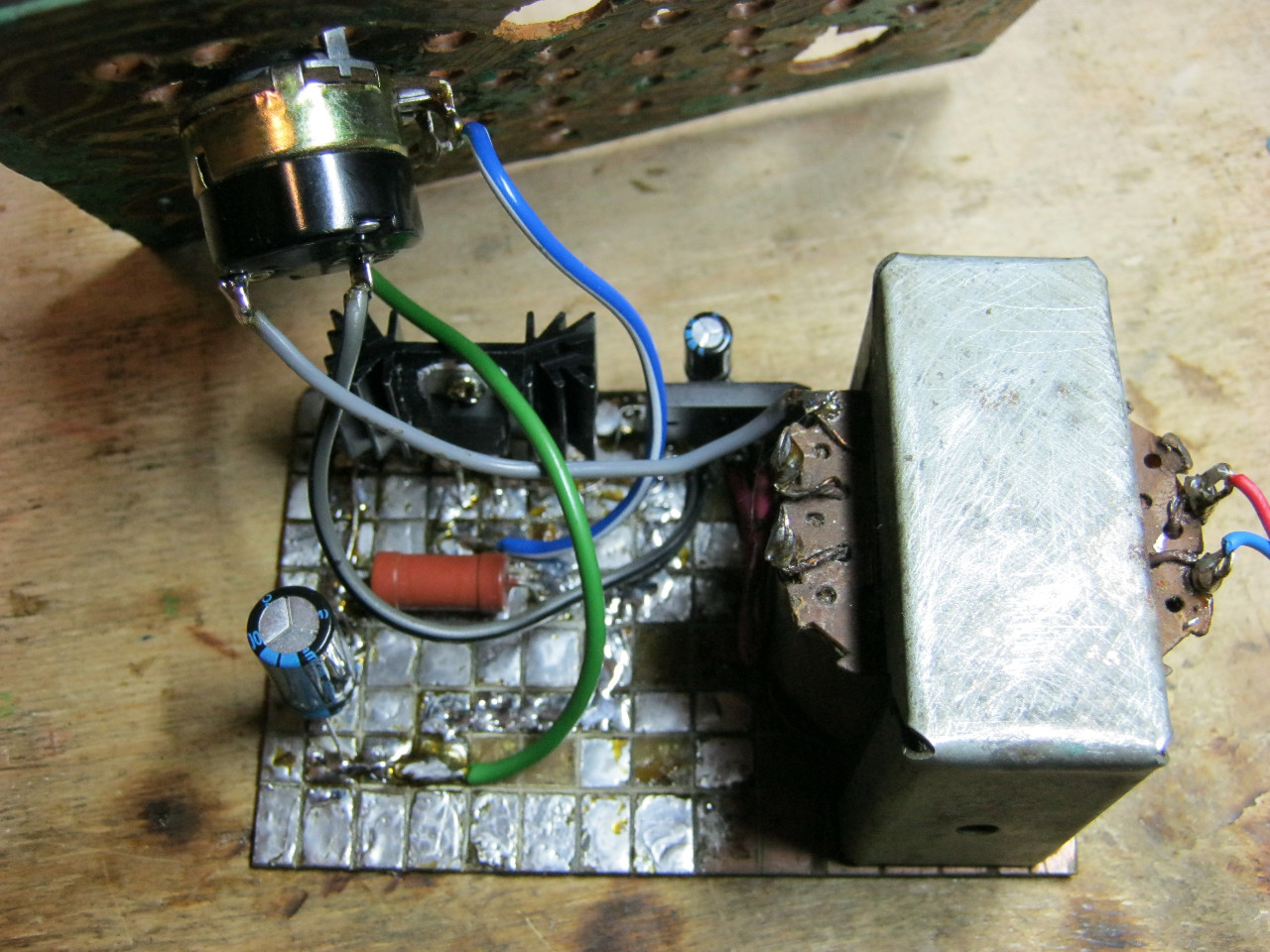
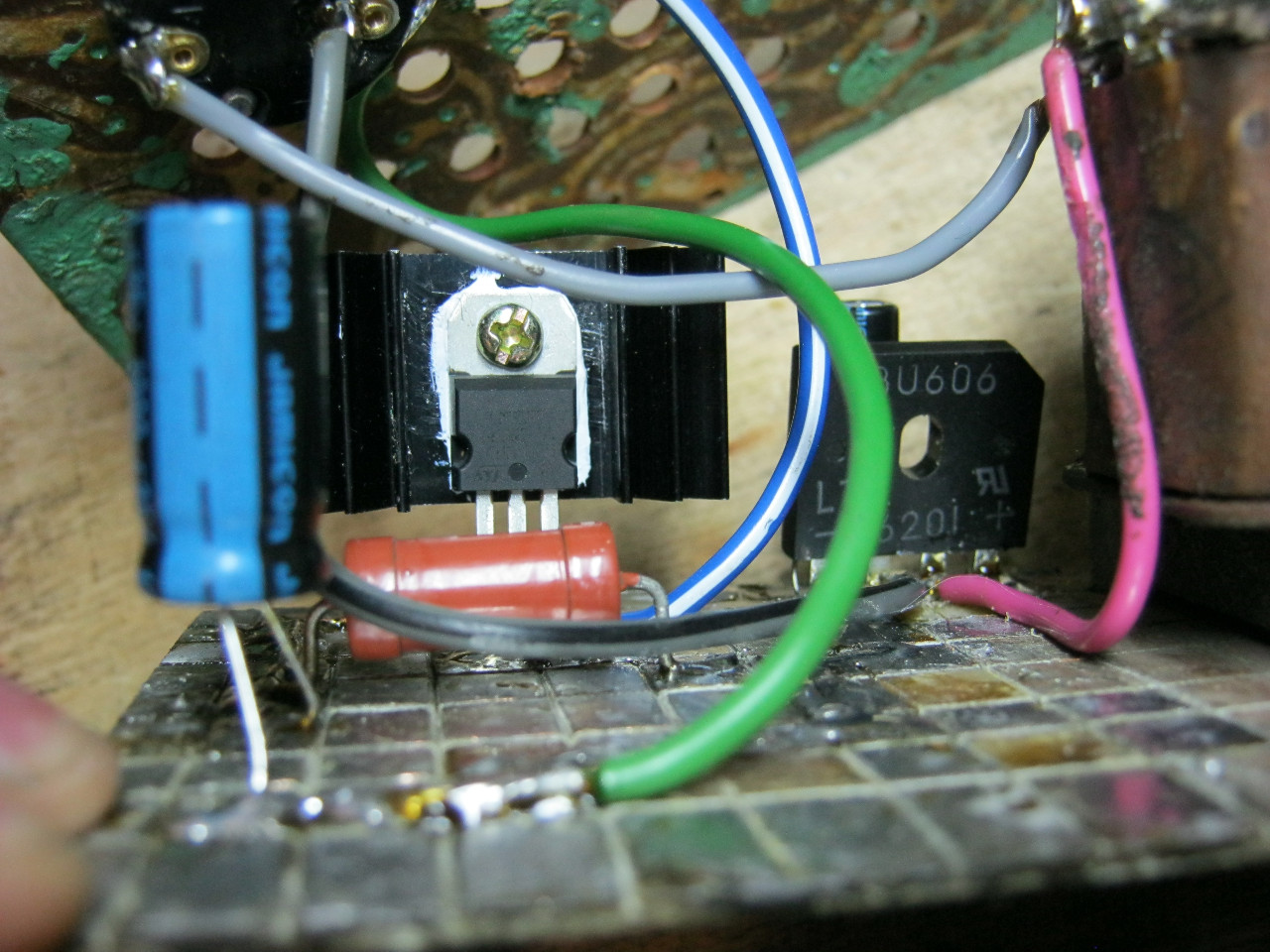
Here we see the imported GBU606 diode bridge. It is designed for a current of up to 6 Amps, which is more than enough for our power supply, since it will deliver a maximum of 1.5 Amps to the load. I installed the LM on the radiator using KPT-8 paste to improve heat transfer. Well, everything else, I think, is familiar to you.
And here is an antediluvian transformer that gives me a voltage of 12 volts on the secondary winding.

We carefully pack all this into the case and remove the wires.
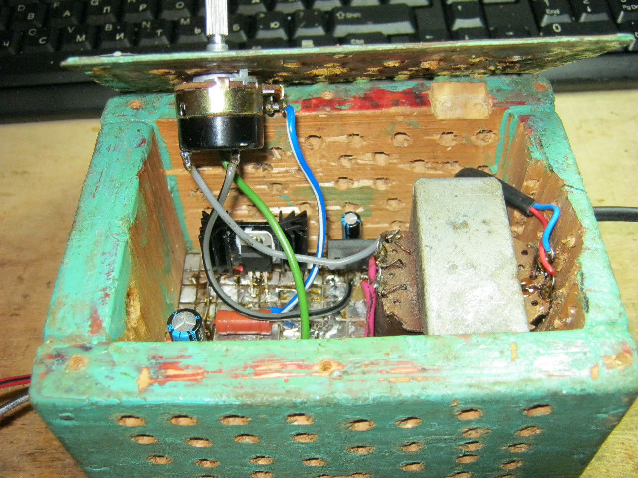
How do you like it? ;-)

The minimum voltage I got was 1.25 Volts, and the maximum was 15 Volts.


I set any voltage, in this case the most common are 12 Volts and 5 Volts
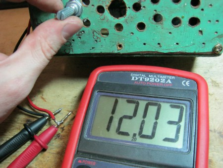

Everything works great!
This power supply is very convenient for adjusting the speed of a mini drill, which is used for drilling circuit boards.
Analogues on Aliexpress
By the way, on Ali you can immediately find a ready-made set of this block without a transformer.

Too lazy to collect? You can buy a ready-made 5 Amp for less than $2:

You can view it at this link.
If 5 Amps is not enough, then you can look at 8 Amps. It will be enough for even the most seasoned electronics engineer:

Making a laboratory power supply with your own hands is not difficult if you have the skills to use a soldering iron and you understand electrical circuits. Depending on the parameters of the source, you can use it to charge batteries, connect almost any household equipment, and use it for experiments and experiments in the design of electronic devices. The main thing during installation is the use of proven circuits and build quality. The more reliable the case and connections, the more convenient it is to work with the power source. It is desirable to have adjustments and devices for monitoring output current and voltage.
The simplest homemade power supply
If you do not have skills in making electrical appliances, then it is better to start with the simplest ones, gradually moving to complex designs. Composition of the simplest constant voltage source:
- Transformer with two windings (primary - for connecting to the network, secondary - for connecting consumers).
- One or four diodes for AC rectification.
- Electrolytic capacitor for cutting off the variable component of the output signal.
- Connecting wires.
If you use one semiconductor diode in the circuit, you will get a half-wave rectifier. If you use a diode assembly or a bridge circuit, then the power supply is called full-wave. The difference is in the output signal - in the second case there is less ripple.

Such a homemade power supply is good only in cases where it is necessary to connect devices with the same operating voltage. So, if you are designing automotive electronics or repairing them, it is better to choose a transformer with an output voltage of 12-14 volts. The output voltage depends on the number of turns of the secondary winding, and the current strength depends on the cross-section of the wire used (the greater the thickness, the greater the current).
How to make bipolar power supply?
Such a source is necessary to ensure the operation of some microcircuits (for example, power amplifiers and low frequencies). A bipolar power supply has the following feature: its output has a negative pole, a positive pole and a common pole. To implement such a circuit, it is necessary to use a transformer, the secondary winding of which has a middle terminal (and the value of the alternating voltage between the middle and extreme ones must be the same). If there is no transformer that satisfies this condition, you can upgrade any one whose network winding is designed for 220 volts.

Remove the secondary winding, but first measure the voltage on it. Count the number of turns and divide by the voltage. The resulting number is the number of turns required to produce 1 volt. If you need to get a bipolar power supply with a voltage of 12 volts, you will need to wind two identical windings. Connect the beginning of one to the end of the second and connect this middle point to the common wire. The two terminals of the transformer must be connected to the diode assembly. The difference from a unipolar source is that you need to use 2 electrolytic capacitors connected in series, the middle point is connected to the device body.
Voltage regulation in a unipolar power supply
The task may not seem very simple, but you can make a regulated power supply by assembling a circuit from one or two semiconductor transistors. But you will need to install at least a voltmeter at the output to monitor the voltage. For this purpose, a dial indicator with an acceptable measurement range can be used. You can purchase a cheap digital multimeter and customize it to suit your needs. To do this, you will need to disassemble it, set the desired switch position using soldering (with a voltage range of 1-15 volts, it is required that the device can measure voltages up to 20 volts).

The regulated power supply can be connected to any electrical device. First, you only need to set the required voltage value so as not to damage the devices. The voltage is changed using a variable resistor. You have the right to choose its design yourself. It could even be a slider type device, the main thing is to comply with the nominal resistance. To make the power supply convenient to use, you can install a variable resistor paired with a switch. This will get rid of the extra toggle switch and make it easier to turn off the equipment.
Voltage regulation in a bipolar source
This design will be more complicated, but it can be implemented quite quickly if all the necessary elements are available. Not everyone can make a simple laboratory power supply, and even a bipolar one with voltage regulation. The circuit is complicated by the fact that it requires the installation of not only a semiconductor transistor operating in switch mode, but also an operational amplifier and zener diodes. When soldering semiconductors, be careful: try not to heat them too much, because their permissible temperature range is extremely small. When overheated, the germanium and silicon crystals are destroyed, causing the device to stop functioning.

When making a laboratory power supply with your own hands, remember one important detail: the transistors must be mounted on an aluminum radiator. The more powerful the power source, the larger the radiator area should be. Pay special attention to the quality of soldering and wires. For low-power devices, thin wires can be used. But if the output current is large, then it is necessary to use wires with thick insulation and a large cross-sectional area. Your safety and ease of use of the device depend on the reliability of switching. Even a short circuit in the secondary circuit can cause a fire, so when manufacturing the power supply, care should be taken to protect it.
Retro style voltage regulation
Yes, this is exactly what you can call making adjustments in this way. To implement it, you need to rewind the secondary winding of the transformer and make several conclusions depending on what voltage step and range you need. For example, a 30V 10A lab power supply in 1 volt increments would have 30 pins. A switch must be installed between the rectifier and the transformer. It is unlikely that you will be able to find one with 30 positions, and if you do find it, its dimensions will be very large. It is clearly not suitable for installation in a small case, so it is better to use standard voltages for manufacturing - 5, 9, 12, 18, 24, 30 volts. This is quite enough for convenient use of the device in the home workshop.

To manufacture and calculate the secondary winding of the transformer you need to do the following:
- Determine what voltage is collected by one turn of the winding. For convenience, wind 10 turns, connect the transformer to the network and measure the voltage. Divide the resulting value by 10.
- Wind the secondary winding, having first disconnected the transformer from the network. If it turns out that one turn collects 0.5 V, then to get 5 V you need to tap from the 10th turn. And using a similar scheme, you make taps for the remaining standard voltage values.

Anyone can make such a laboratory power supply with their own hands, and most importantly, there is no need to solder a circuit with transistors. Connect the secondary winding leads to a switch so that the voltage values change from lower to higher. The central terminal of the switch is connected to the rectifier, the lower terminal of the transformer according to the diagram is supplied to the device body.
Features of switching power supplies

Such circuits are used in almost all modern devices - in phone chargers, power supplies for computers and televisions, etc. Making a laboratory power supply, especially a switching one, turns out to be problematic: too many nuances need to be taken into account. Firstly, the circuit is relatively complex and the principle of operation is not simple. Secondly, most of the device operates under high voltage, which is equal to that flowing in the network. Look at the main components of such a power supply (using the example of a computer):
- A network rectification unit designed to convert 220 volt alternating current into direct current.
- An inverter that converts DC voltage into high frequency square wave signals. This also includes a special pulse-type transformer, which reduces the voltage to power the PC components.
- Control responsible for the correct operation of all elements of the power supply.
- An amplification stage designed to amplify PWM controller signals.
- Block for stabilization and rectification of output pulse voltage.

Similar components and elements are present in all switching power supplies.
Computer power supply
The cost of even a new power supply that is installed in computers is quite low. But you get a ready-made design; you don’t even have to make a chassis. One drawback is that the output has only standard voltage values (12 and 5 volts). But for a home laboratory this is quite enough. A lab power supply made from ATX is popular because there is no need to make major modifications. And the simpler the design, the better. But there are also “diseases” with such devices, but they can be cured quite simply.

Electrolytic capacitors often fail. Electrolyte leaks out of them, this can be seen even with the naked eye: a layer of this solution appears on the printed circuit board. It is gel-like or liquid, and over time it hardens and becomes hard. To repair a laboratory power supply from a computer power supply, you need to install new electrolytic capacitors. The second failure, which is much less common, is the breakdown of one or more semiconductor diodes. The symptom is a failure of the fuse mounted on the printed circuit board. To repair, you need to ring all the diodes installed in the bridge circuit.
Methods for protecting power supplies
The easiest way to protect yourself is to install fuses. You can use such a laboratory power supply with protection without fear that a fire will occur due to a short circuit. To implement this solution, you will need to install two fuses in the power supply circuit of the mains winding. They need to be taken at a voltage of 220 volts and a current of about 5 amperes for low-power devices. Suitable fuses must be installed at the output of the power supply. For example, when protecting a 12-volt output circuit, you can use fuses used in cars. The current value is selected based on the maximum power of the consumer.

But this is the age of high technology, and making protection using fuses is not very profitable from an economic point of view. It is necessary to replace the elements after each accidental touching of the power wires. As an option, install self-restoring fuses instead of conventional fuse links. But they have a small resource: they can serve faithfully for several years, or they can fail after 30-50 outages. But a 5A laboratory power supply, if assembled correctly, functions correctly and does not require additional protection devices. The elements cannot be called reliable; household appliances often become unusable due to the failure of such fuses. It is much more effective to use a relay circuit or a thyristor circuit. Triacs can also be used as an emergency shutdown device.
How to make a front panel?
Most of the work is designing the enclosure rather than assembling the electrical circuit. You will have to arm yourself with a drill, files, and if painting is necessary, you will also have to master painting. You can make a homemade power supply based on the case from some device. But if you have the opportunity to purchase sheet aluminum, then if you wish, you can make a beautiful chassis that will serve you for many years. To begin, draw a sketch in which you arrange all the structural elements. Pay special attention to the design of the front panel. It can be made of thin aluminum, only reinforced from the inside - screwed to aluminum corners, which are used to give greater rigidity to the structure.

The front panel must have holes for installing measuring instruments, LEDs (or incandescent lamps), terminals connected to the output of the power supply, and sockets for installing fuses (if this protection option is selected). If the appearance of the front panel is not very attractive, then it needs to be painted. To do this, degrease and clean the entire surface until shiny. Before starting painting, make all the necessary holes. Apply 2-3 layers of primer to the heated surface and let dry. Next, apply the same number of layers of paint. Varnish should be used as a finishing coat. As a result, a powerful laboratory power supply, thanks to the paint and the resulting shine, will look beautiful and attractive and will fit into the interior of any workshop.
How to make a chassis for a power supply?
Only a design that is completely made independently will look beautiful. But you can use anything as a material: from sheet aluminum to personal computer cases. You just need to carefully think through the entire design so that unforeseen situations do not arise. If the output stages require additional cooling, install a cooler for this purpose. It can work both constantly when the device is turned on, and in automatic mode. To implement the latter, it is best to use a simple microcontroller and a temperature sensor. The sensor monitors the temperature of the radiator, and the microcontroller contains the value at which it is necessary to turn on the air blowing. Even a 10A laboratory power supply, whose power is quite large, will work stably with such a cooling system.

Airflow requires air from outside, so you will need to install a cooler and radiator on the rear wall of the power supply. To ensure chassis rigidity, use aluminum corners, from which you first form a “skeleton”, and then install the casing on it - plates made of the same aluminum. If possible, connect the corners by welding, this will increase strength. The lower part of the chassis must be strong, since the power transformer is mounted on it. The higher the power, the larger the dimensions of the transformer, the greater its weight. As an example, we can compare a 30V 5A laboratory power supply and a similar design, but at 5 volts and a current of about 1 A. The latter will have much smaller dimensions and light weight.
There must be a layer of insulation between the electronic components and the housing. You need to do this exclusively for yourself, so that in the event of an accidental break in the wire inside the unit, it does not short out to the housing. Before installing the sheathing on the “skeleton”, insulate it. You can stick thick cardboard or thick adhesive tape. The main thing is that the material does not conduct electricity. With this modification, security is improved. But the transformer can produce an unpleasant hum, which can be eliminated by fixing and gluing the core plates, as well as installing rubber pads between the body and chassis. But you will get the maximum effect only by combining these solutions.
Summing up
In conclusion, it is worth mentioning that all installation and testing work is carried out in the presence of life-threatening voltage. Therefore, you need to think about yourself; be sure to install automatic switches in the room, paired with protective shutdown devices. Even if you touch the phase, you will not receive an electric shock, since the protection will work.
When working with switching power supplies for computers, follow safety precautions. The electrolytic capacitors in their design remain energized for a long time after switching off. For this reason, before starting repairs, discharge the capacitors by connecting their leads. Just don’t be alarmed by the spark; it will not harm you or the devices.

When making a laboratory power supply with your own hands, pay attention to all the little things. After all, the main thing for you is to ensure stable, safe and convenient operation. And this can only be achieved if all the little details are carefully thought out, not only in the electrical circuit, but also in the device body. Monitoring devices will not be superfluous in the design, so install them to have an idea of, for example, what current the device you assembled in your home laboratory consumes.
The master whose device was described in the first part, having set out to make a power supply with regulation, did not complicate things for himself and simply used boards that were lying idle. The second option involves the use of an even more common material - an adjustment has been added to the usual block, perhaps this is a very promising solution in terms of simplicity, given that the necessary characteristics will not be lost and even the most experienced radio amateur can implement the idea with his own hands. As a bonus, there are two more options for very simple schemes with all the detailed explanations for beginners. So, there are 4 ways for you to choose from.
We'll tell you how to make an adjustable power supply from an unnecessary computer board. The master took the computer board and cut out the block that powers the RAM.
This is what he looks like.
Let's decide which parts need to be taken and which ones not, in order to cut off what is needed so that the board has all the components of the power supply. Typically, a pulse unit for supplying current to a computer consists of a microcircuit, a PWM controller, key transistors, an output inductor and an output capacitor, and an input capacitor. For some reason, the board also has an input choke. He left him too. Key transistors - maybe two, three. There is a seat for 3 transistors, but it is not used in the circuit.
The PWM controller chip itself may look like this. Here she is under a magnifying glass.

It may look like a square with small pins on all sides. This is a typical PWM controller on a laptop board.

This is what a switching power supply looks like on a video card.

The power supply for the processor looks exactly the same. We see a PWM controller and several processor power channels. 3 transistors in this case. Choke and capacitor. This is one channel.
Three transistors, a choke, a capacitor - the second channel. Channel 3. And two more channels for other purposes.
You know what a PWM controller looks like, look at its markings under a magnifying glass, search for a datasheet on the Internet, download the pdf file and look at the diagram so as not to confuse anything.
In the diagram we see a PWM controller, but the pins are marked and numbered along the edges.

Transistors are designated. This is the throttle. This is an output capacitor and an input capacitor. The input voltage ranges from 1.5 to 19 volts, but the supply voltage to the PWM controller should be from 5 volts to 12 volts. That is, it may turn out that a separate power source is required to power the PWM controller. All the wiring, resistors and capacitors, don’t be alarmed. You don't need to know this. Everything is on the board; you do not assemble a PWM controller, but use a ready-made one. You only need to know 2 resistors - they set the output voltage.
Resistor divider. Its whole point is to reduce the signal from the output to about 1 volt and apply feedback to the input of the PWM controller. In short, by changing the value of the resistors, we can regulate the output voltage. In the case shown, instead of a feedback resistor, the master installed a 10 kilo-ohm tuning resistor. This was sufficient to regulate the output voltage from 1 volt to approximately 12 volts. Unfortunately, this is not possible on all PWM controllers. For example, on PWM controllers of processors and video cards, in order to be able to adjust the voltage, the possibility of overclocking, the output voltage is supplied by software via a multi-channel bus. The only way to change the output voltage of such a PWM controller is by using jumpers.

So, knowing what a PWM controller looks like and the elements that are needed, we can already cut out the power supply. But this must be done carefully, since there are tracks around the PWM controller that may be needed. For example, you can see that the track goes from the base of the transistor to the PWM controller. It was difficult to save it; I had to carefully cut out the board.
Using the tester in dial mode and focusing on the diagram, I soldered the wires. Also using the tester, I found pin 6 of the PWM controller and the feedback resistors rang from it. The resistor was located in the rfb, it was removed and instead of it, a 10 kilo-ohm tuning resistor was soldered from the output to regulate the output voltage; I also found out by calling that the power supply of the PWM controller is directly connected to the input power line. This means that you cannot supply more than 12 volts to the input, so as not to burn out the PWM controller.
Let's see what the power supply looks like in operation
I soldered the input voltage plug, voltage indicator and output wires. We connect an external 12 volt power supply. The indicator lights up. It was already set to 9.2 volts. Let's try to adjust the power supply with a screwdriver.

It's time to check out what the power supply is capable of. I took a wooden block and a homemade wirewound resistor made from nichrome wire. Its resistance is low and, together with the tester probes, is 1.7 Ohms. We turn the multimeter into ammeter mode and connect it in series with the resistor. See what happens - the resistor heats up to red, the output voltage remains virtually unchanged, and the current is about 4 amperes.

The master had already made similar power supplies before. One is cut out with your own hands from a laptop board.

This is the so-called standby voltage. Two sources of 3.3 volts and 5 volts. I made a case for it on a 3D printer. You can also look at the article where I made a similar adjustable power supply, also cut from a laptop board (https://electro-repair.livejournal.com/3645.html). This is also a PWM power controller for RAM.
How to make a regulating power supply from a regular printer
We will talk about the power supply for a Canon inkjet printer. Many people have them idle. This is essentially a separate device, held in the printer by a latch.
Its characteristics: 24 volts, 0.7 amperes.

I needed a power supply for a homemade drill. It's just right in terms of power. But there is one caveat - if you connect it like this, the output will only get 7 volts. Triple output, connector and we get only 7 volts. How to get 24 volts?
How to get 24 volts without disassembling the unit?
Well, the simplest one is to close the plus with the middle output and we get 24 volts.
Let's try to do it. We connect the power supply to the 220 network. We take the device and try to measure it. Let's connect and see 7 volts at the output.
Its central connector is not used. If we take it and connect it to two at the same time, the voltage is 24 volts. This is the easiest way to ensure that this power supply produces 24 volts without disassembling it.
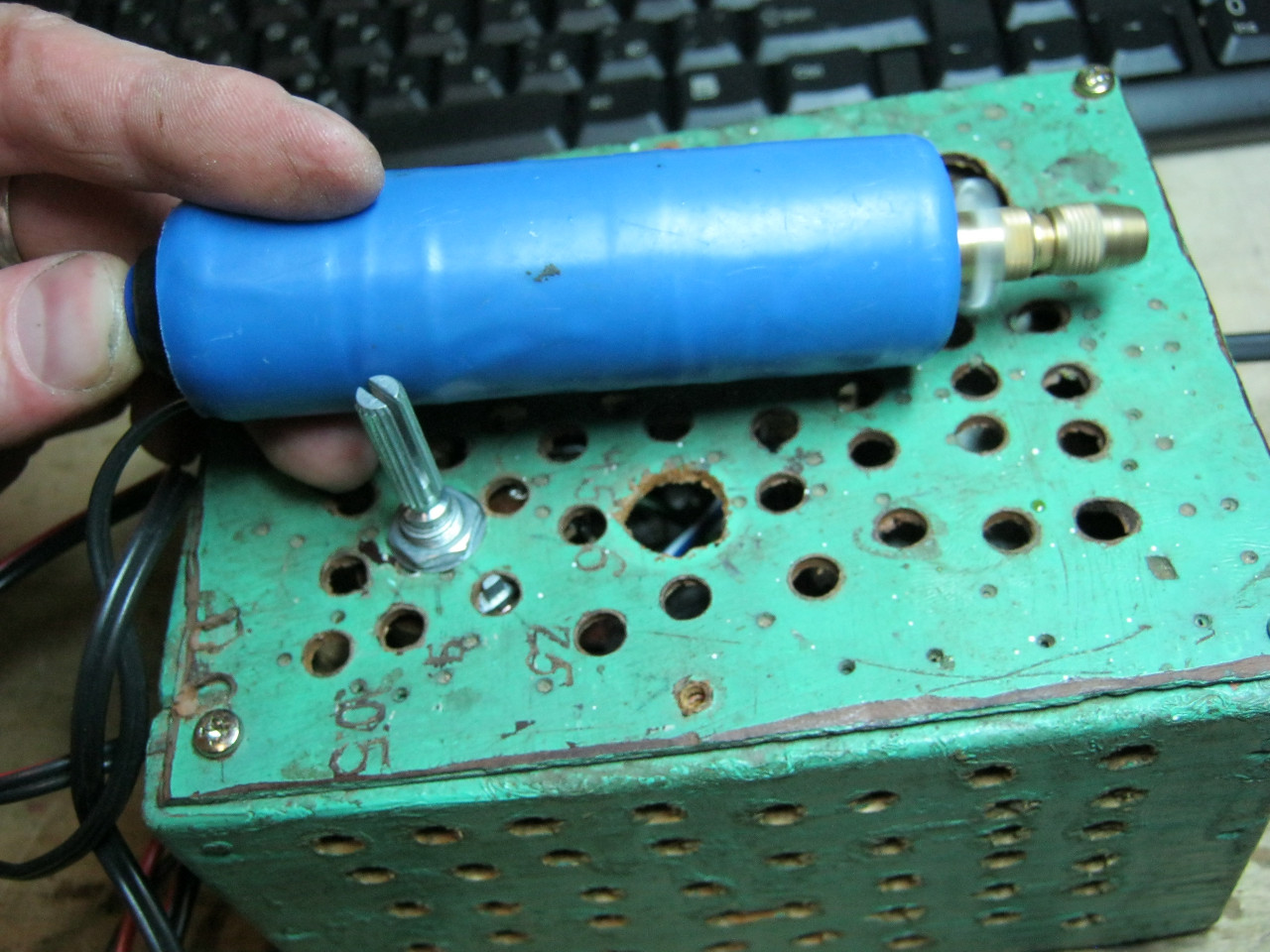
A homemade regulator is needed so that the voltage can be adjusted within certain limits. From 10 volts to maximum. It's easy to do. What is needed for this? First, open the power supply itself. It is usually glued. How to open it without damaging the case. There is no need to pick or pry anything. We take a piece of wood that is heavier or have a rubber mallet. Place it on a hard surface and tap along the seam. The glue comes off. Then they tapped thoroughly on all sides. Miraculously, the glue comes off and everything opens up. Inside we see the power supply.

We'll get the payment. Such power supplies can be easily converted to the desired voltage and can also be made adjustable. On the reverse side, if we turn it over, there is an adjustable zener diode tl431. On the other hand, we will see the middle contact goes to the base of transistor q51.


If we apply voltage, then this transistor opens and 2.5 volts appears at the resistive divider, which is needed for the zener diode to operate. And 24 volts appears at the output. This is the simplest option. Another way to start it is to throw out transistor q51 and put a jumper instead of resistor r 57 and that’s it. When we turn it on, the output is always 24 volts continuously.
How to make the adjustment?
You can change the voltage, make it 12 volts. But in particular, the master does not need this. You need to make it adjustable. How to do it? We throw away this transistor and replace the 57 by 38 kilo-ohm resistor with an adjustable one. There is an old Soviet one with 3.3 kilo-ohms. You can put from 4.7 to 10, which is what it is. Only the minimum voltage to which it can lower it depends on this resistor. 3.3 is very low and not necessary. The engines are planned to be supplied at 24 volts. And just from 10 volts to 24 is normal. If you need a different voltage, you can use a high-resistance tuning resistor.
Let's get started, let's solder. Take a soldering iron and hair dryer. I removed the transistor and resistor.

We soldered the variable resistor and will try to turn it on. We applied 220 volts, we see 7 volts on our device and begin to rotate the variable resistor. The voltage has risen to 24 volts and we rotate it smoothly and smoothly, it drops - 17-15-14, that is, it decreases to 7 volts. In particular, it is installed on 3.3 rooms. And our rework turned out to be quite successful. That is, for purposes from 7 to 24 volts, voltage regulation is quite acceptable.

This option worked out. I installed a variable resistor. The handle turns out to be an adjustable power supply - quite convenient.
Video of the channel “Technician”.
Such power supplies are easy to find in China. I came across an interesting store that sells used power supplies from various printers, laptops and netbooks. They disassemble and sell the boards themselves, fully functional for different voltages and currents. The biggest plus is that they disassemble branded equipment and all power supplies are of high quality, with good parts, all have filters.
The photos are of different power supplies, they cost pennies, practically a freebie.
Simple block with adjustment
A simple version of a homemade device for powering devices with regulation. The scheme is popular, it is widespread on the Internet and has shown its effectiveness. But there are also limitations, which are shown in the video along with all the instructions for making a regulated power supply.


Homemade regulated unit on one transistor
What is the simplest regulated power supply you can make yourself? This can be done on the lm317 chip. It almost represents a power supply itself. It can be used to make both a voltage- and flow-regulated power supply. This video tutorial shows a device with voltage regulation. The master found a simple scheme. Input voltage maximum 40 volts. Output from 1.2 to 37 volts. Maximum output current 1.5 amperes. 
Without a heat sink, without a radiator, the maximum power can be only 1 watt. And with a radiator 10 watts. List of radio components. 
Let's start assembling 


Let's connect an electronic load to the output of the device. Let's see how well it holds current. We set it to minimum. 7.7 volts, 30 milliamps.
 Everything is regulated. Let's set it to 3 volts and add current. We will only set higher restrictions on the power supply. We move the toggle switch to the upper position. Now it's 0.5 ampere. The microcircuit began to warm up. There is nothing to do without a heat sink. I found some kind of plate, not for long, but enough. Let's try again. There is a drawdown. But the block works. Voltage adjustment is in progress. We can insert a test into this scheme.
Radioblogful video. Soldering video blog.
I recently came across on the Internet an interesting diagram of a simple but quite good entry-level power supply capable of delivering 0-24 V at a current of up to 5 amperes. The power supply provides protection, that is, limiting the maximum current in case of overload. The attached archive contains a printed circuit board and a document that describes the configuration of this unit, and a link to the author’s website. Please read the description carefully before assembling.

Here is a photo of my version of the power supply, a view of the finished board, and you can see how to roughly use a case from an old ATX computer. The adjustment is made 0-20 V 1.5 A. Capacitor C4 for this current is set to 100 uF 35 V.

When there is a short circuit, the maximum limited current is output and the LED lights up, bringing the limiter resistor to the front panel.
Power supply indicator
I carried out an audit and found a pair of simple M68501 pointer heads for this power supply. I spent half a day creating a screen for it, but I finally drew it and fine-tuned it to the required output voltages.

The resistance of the indicator head used and the resistor used are indicated in the attached file on the indicator. I’m laying out the front panel of the unit, if anyone needs to remodel the case from an ATX power supply, it will be easier to rearrange the inscriptions and add something than to create from scratch. If other voltages are required, the scale can simply be calibrated, this will be easier. Here is a finished view of the regulated power supply:

The film is a self-adhesive "bamboo" type. The indicator has a green backlight. Red LED Attention indicates that overload protection has been activated.

Add-ons from BFG5000
The maximum limiting current can be made more than 10 A. On the cooler - 12 volts plus a temperature speed controller - from 40 degrees the speed begins to increase. The circuit error does not particularly affect the operation, but judging by the measurements during a short circuit, there is an increase in the passing power.

The power transistor was installed 2n3055, everything else is also foreign analogues, except for BC548 - installed KT3102. The result was a truly indestructible power supply. Just the thing for beginner radio amateurs.

The output capacitor is set to 100 uF, the voltage does not jump, the adjustment is smooth and without visible delays. I set it based on the calculation as indicated by the author: 100 microfarads of capacity per 1 A of current. Authors: Igoran And BFG5000.
Discuss the article POWER SUPPLY WITH CURRENT AND VOLTAGE REGULATION