DIY indoor antenna made from coaxial cable. The best outdoor antennas for digital television. Loop from a pipe
Which antenna to choose for digital television? How are antennas different? How to supply power to an active antenna? Which antenna is better? These and other questions on the site
Hi all! Due to my line of work, I have to deal very closely with connecting and setting up antennas for digital terrestrial television.
Therefore, based on the experience gained, I have the opportunity to share how to choose an antenna for digital television and set up dvb-t2 - free 20 channels.
Quick navigation through the article
Which antenna is suitable for DVB-T2 digital television
With the advent of digital terrestrial television, many people have questions related to the choice of antenna for DVB-T2. For example!
- Can I use my old antenna, if I had one?
- Is an antenna of the “Lattice” type, also known as “Polish”, suitable for this?
- Do I need an antenna with or without an amplifier?
- if there is a question about purchasing a new one?
- Is the advertised “Key to Free TV” antenna necessary?
Let's first figure out what kind of antennas there are.
Antennas of the meter (MV) and decimeter (UHF) ranges are used to receive television signals. There are broadband antennas, this is a “hybrid” when elements of the MV and UHF bands are used in the antenna design.
These antennas are easy to distinguish from each other by size.
The MV range has longer elements. Everything is according to the name.
So in MV antennas the elements are approximately half a meter to one and a half meters in length.
And the elements of the UHF antenna are only about 15 to 40 cm long.
Exactly UHF antenna range is needed for digital terrestrial television.
 VHF Antenna
  Example of a UHF antenna
  Broadband antenna, MV and UHF ranges.
  Array antenna
 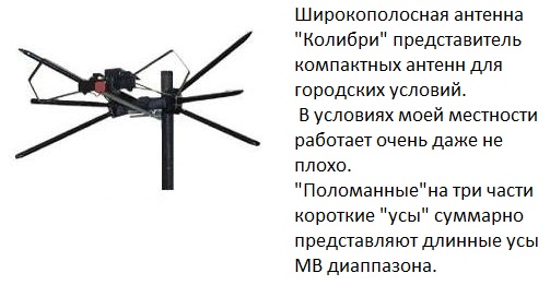 Broadband antenna"Hummingbird"
 So - To receive digital terrestrial television you need a UHF antenna, i.e. antenna with short elements. Or broadband.
Now you can evaluate whether your old antenna is suitable for receiving television in the DVB -T2 format. The only question that remains open is its serviceability and effectiveness in your area.
In addition to dividing by received ranges, antennas are also divided into...
Indoor and outdoor (External) - I think everything is clear with the application here.
And also active and passive - more on that a little later.
Well, a brief excursion into the difficult topic of terrestrial antennas has been carried out. Let's continue...
Features of television signal propagation
The distance over which the signal is transmitted in the UHF range does not have a large coverage area. It is much less than in the meter range.
For example:
If you have used a radio, you may have noticed that you cannot catch distant foreign radio stations in the FM or VHF bands, but only those nearby, local ones.
But on the other hand, you can catch a whole bunch of foreign ones in the CB or HF bands.
This is because medium and short waves, like meter ones, propagate over long distances, and ultrashort waves, like UHF, over short distances.
This disadvantage of the UHF range for digital TV is compensated by the location and number of television transmitters - similar to towers cellular communication, there are many of them.
Also keep in mind that the television signal is perfectly reflected from objects encountered along the way.
This allows you to receive broadcasts when it is not possible to point the antenna towards the TV tower. Or there are obstacles to the direct passage of the signal.
Look around! Is it possible to receive a reflected signal?
So with the right choice of antenna and its correct installation, you will surely succeed.

What else should you consider when choosing an antenna?
Admission conditions TV signal very different in different places and these conditions must be taken into account when choosing an antenna.
Here are some factors that will determine which antenna you need to purchase and how to install it.
- TV transmitter power and
- Terrain - mountains, lowlands, plains.
- Standing nearby and blocking the antenna in the direction of the tower are tall, dense trees.
- The presence of high-rise buildings and your location in relation to these buildings and the tower.
- The floor you live on - the higher you are, the simpler the antenna you will need.
- Possibility or impossibility of turning the antenna towards the transmitting tower.
Active and passive antennas - what is the difference?
Antennas of any type can be either active or passive.
Passive antennas are those that amplify the signal only due to their design, without the use of electronic amplifiers; such antennas are used in areas with a strong signal.
Active antenna - has an amplifier in its design; such an antenna needs to be connected to a power source.
The amplifier helps to increase the level of the received signal in areas of poor reception.
How to connect power to an active antenna amplifier, several ways
Antenna amplifiers are powered by 12 or 5 volts. But in lately Increasingly, manufacturers are focusing on producing antennas with five-volt power supply.
And there is a reason for this! Such antennas are easier to connect for those who use a DVB-T2 set-top box.
Three connection methods
A) Use a special power supply with a separator that produces a voltage corresponding to your amplifier.
The purpose of a separator is to separate. It passes voltage to the antenna, but does not pass it to the TV socket. However, this does not interfere with the signal from the antenna amplifier entering the TV.
B) If a DVB-T2 set-top box is used. A voltage of 5 volts can be supplied directly from the set-top box. Moreover, for any amplifiers, both 5 and 12 volts.
This does not require any additional wire, power supply, etc. The voltage is 5 volts, from the antenna socket of the set-top box, directly through the antenna cable, it will go to the amplifier.
You just need to turn on this power directly from the set-top box menu. Go to the settings section and find the item “Antenna power ON-OFF”, select ON, and exit the menu (in various models prefixes, the names of these items may differ)
B) If you have an LCD TV with a built-in DVB-T2 tuner, then in addition to the method under letter A) you can do the following.
You will have to purchase a special adapter to power the amplifier from any USB port and, first of all, the USB port of the LCD TV itself is considered. But you can connect to anyone charger with USB output

Which antenna to choose - let's look at examples
As you understand from all of the above, when choosing an antenna for yourself, you need to evaluate various factors.
Some examples:
Distance to the tower 5-15 km
You live in a city where there is a DVB-T2 signal transmitter. Or in a populated area, not far from the transmitter, 5-15 km.
Most likely, an indoor antenna, even the simplest one, will be suitable for you. Especially if you live above the first floor.
And being not far from the tower, even a simple piece of wire instead of an antenna may be enough.
Considering the prevalence of towers and quite large number places with a reliable signal, scammers take advantage of this by offering various, essentially
Under the conditions described above, they will work well.
But keep in mind that the number of channels will not be more than that broadcast by the TV tower in your area! But not 100 or 200 as the advertisement promises.
Therefore, the question arises: is it necessary to shell out several hundred, or even thousands, for a regular indoor antenna from an advertisement?!
Here are several inexpensive, compact antenna options for conditions where there is a good signal.
 Indoor antenna for places close to the tower.
  Indoor antenna for places close to the tower. Another option
  This option may work in slightly more difficult conditions than the previous two, especially the amplified version.
 Indoor antenna - application features
The right place for an indoor antenna is not where it will look good and stand comfortably, this is where it will receive the signal well. And these two circumstances - “look” and “accept” - do not always coincide.
Because often the best, and sometimes the only place where you can catch a signal is a place at the window facing the TV tower. Take this into account!
To solve this problem, you can add a cable of the required length, and for some antennas (for example, those in the photo above) this is not difficult.
But there are indoor antennas that have a built-in power supply in their housing. They also have power cord to connect to an outlet. And of course a cable for connecting to a TV.

This may seem convenient, but unfortunately this is not always the case.
Often, the place where the antenna is capable of receiving a TV signal is not near the TV and outlet, but, for example, near a window.
And in this case, a short power cord will become an obstacle to placing the antenna in the right place. In addition to the cable, you will also have to pull an extension cord. Basically a lot of wires.
You live at a distance of about 25-30 km or more from the TV tower.
Of course, a lot depends on the power of the transmitter.
But in general, at a distance of 25 km, a small outdoor antenna is sufficient. Like, for example, those depicted at the very beginning of this post, we mean the UHF antenna or the broadband “Hummingbird”.
In my area, from a distance of 25 km in line of sight, a passive UHF antenna with an arm length of approximately 80 cm provides reliable reception without the need to raise the antenna above two meters from the ground.
You can also receive reception using a good active indoor antenna.
In some houses, even from the first floor, if there is a window towards the tower or the ability to receive a reflected signal from neighboring buildings.
A floor above the second significantly increases the likelihood of success.
There is a simple principle on how to determine the power of an antenna - the longer the antenna arm, the greater the coefficient of its own gain, and not due to the amplifier.
Antenna for difficult signal reception conditions
For example, the active antenna in the photo below, in our area, pulls out a signal from a distance of 60 km or more. It is successfully used in the most difficult places, in houses located in deep lowlands, its length is approximately 1.7 meters, but there are antennas up to 4 meters in length.
 In addition to the length, it plays in difficult conditions or at a strong distance from the TV tower important role presence of an amplifier, i.e. the antenna must be active.
There are options powerful antennas, where instead of one boom, three are used at once, so the ability of the antenna to amplify the signal due to the design alone is greatly increased.
And in tandem with an amplifier, this antenna becomes a very powerful trap for a television signal.

But once you’re impressed with this antenna, don’t rush to run after it. It is only needed under really, really difficult reception conditions.
In most cases, other, much cheaper options are sufficient. In addition, if the signal in your area is already strong, then the amplifier in the antenna will only interfere.
This is exactly the case when porridge can be ruined with butter. An example of this is described below.
Polish antenna array for digital television
In some cases, the “Grid” antenna can work quite successfully when receiving digital television. Especially if you are not very close to the transmitting tower.
More than once, however, I came across a situation where, using their old antenna - Polyachka (Grid), people could not get a signal from it digital broadcasting.
Either at all, or the signal periodically “fell off”; the picture crumbled into cubes, and there was freezing of the image and sound. One of the digital television packages could disappear, while the other was working normally.
The problem with these phenomena is over-amplification of the signal.
There is a way out, let's consider the options...
1) Sometimes it’s just enough to unplug the antenna’s power supply from the outlet and that’s it. But this does not always help and then more serious measures are needed.
2) Reduce the amplifier supply voltage using adjustable block nutrition. Or supply power directly from the set-top box, bypassing the separator of the standard antenna power supply, by installing a regular plug.
3) Get to the amplifier board, the board that is on the antenna itself, and connect everything without an amplifier.
4) Throw away this old dilapidated antenna and buy a normal UHF antenna.
P.S. New type grille.
I hope this article will be useful to someone, leave your reviews, comments, and share your experience.
P.S. If you are purchasing a new antenna but are not sure whether it will suit you, ask your local antenna dealer.
Sometimes they are quite knowledgeable about which antenna is best to take based on your place of residence.
And agree on the possibility, if it suddenly doesn’t work, to change it to a different type of antenna. At least in my store this is possible.
Modernization of the "Polish" antenna for T2
You can use the “Polish” antenna completely assembled with an amplifier without modification, but as experience shows, some frequency channels have a weak signal level.
We are all surprised by the versatility of the “Polish” antenna, and the Polish antenna is nothing more than the simplest combination of the simplest universal “butterfly” antenna, widely known since the 60s, with a vibrator length of 1150 mm and an opening angle of 38° for reception from 1 to 12 th channel in line of sight conditions
and a primitively designed “wave channel antenna”, and not a single size fits into any calculations or GOSTs. That is, we have a usual, practically, dummy UHF antenna in a “Polish” antenna for UHF reception (I’m talking about directors-passive selectors). It turns out that only a “butterfly” works in this antenna, or rather several “butterfly”-active selectors and I will also note those designed for a certain range (they are all the same length), and an SWA amplifier.
If you remove the SWA amplifier, the antenna will not work. What I am saying is that it is enough to bend such an active vibrator of a certain size (we will talk about this below), connect the SWA amplifier. To balance the RF, you need to run the cable along the arm of the vibrator according to Fig. 2. Effect we'll get a much better "Polish"
ATTENTION: the cable is routed along the arm of the active vibrator that is connected to the “body” of the amplifier circuit! At the midpoint of the vibrator, where the HF potential is zero, we bend the cable smoothly and direct it along the traverse, then downward.
In short, any homemade antenna + SWA amplifier works much better better than any"Poles".
But we already have what we have. Let’s try to bring it a little into a normal UHF form. “Meter” mustaches (long active vibrators, see Fig. 1) are absolutely not needed; if we use an antenna for T2 (UHF wavelength), they can be cut to the same length as decimeter active vibrators. If one of the received channels is weaker than the others, you should try to remove the reflector sheet from the active vibrators. With this adjustment of the antenna, its output impedance increases and changes frequency response. Changing the antenna impedance does no harm at all, since the input impedance of the amplifier is higher than the antenna impedance. Radio amateurs with experience working with antenna amplifiers, they can remove the matching-balancing elements on the ferrite ring from the amplifier circuit, this will expand the operating range active antenna. One of the antenna input terminals is connected to the amplifier input, and the second is connected to the “case” of the amplifier circuit.
The antenna resistance at equal received power is related to the output voltage
P=U2/R. U=(P*R)½.
The conclusion that follows is that it is necessary to increase the output impedance of the antenna (the input impedance of the amplifier is greater than the impedance of the antenna). Antennas with a resistance higher than 300 ohms can be successfully used. This connection method is also suitable for a wide-range antenna of the “wave channel” type (more on this later), and in a log-periodic antenna the output cable is balanced, passing through the antenna element (according to the principle of Fig. 2).
Somehow I have a lot of abstruse anecdotes, you’ll think that I’m as smart as.... No, it’s all simple - should you google mine?
I'll try to keep it simpler
I don’t recommend trimming “long mustaches” if you’re doing it for yourself, if you’re lazy, or for your “uncle,” I advise you to shorten it based on L (Length of the vibrator) = 1/2j (half the average length of the weak frequency channel)
And for ourselves, we bend two diamonds and remove the reflector from the back of the diamonds, or insert the sleeve into the mount and bend it 10 cm
Now let’s do some magic with the directors. I have already mentioned the “wave channel” antenna, this miracle is known from the times of black and white TV
So let’s take the dimensions of the directors and the distances between them from the “grandfather’s” antenna that has been tested over the years.
Vibrator no. length in mm distance in mm
7…………………………..107...............0
6…………………………..129..............80
5…………………………..155..............94
4…………………………..186..............77
3…………………………..225..............63
2…………………………..272..............53
1…………………………..330...............43
0....................................... ...........35
High-quality MV-UHF antenna "wave channel" with your own hands
This type of antenna refers to targeted UHF antennas.
Since the gain of the targeted UHF antenna is better than that of the Polish-array, it was decided to make a “hybrid” from the old domestic UHF antenna and the ASP-8 Polish-array with its amplifier. It worked! The image quality of weak images has improved noticeably. The idea of making it was proposed somewhere by someone, all that remained was to implement it.
I will tell you simply, without any abstruse expressions and formulas.
For self-made antennas needed:
Special program to calculate Antwu15;
1 or 2 amplifiers from the grid (with housings);
Aluminum pipe cross section? o 25mm and length? 2m. (traverse);
3 aluminum tubes with a cross-section of up to o10mm, two lengths of 1m each (MV) and another? 2.5-3m. (for cutting UHF elements);
2 sheets of textolite 3-5 mm thick, dimensions: 300mmx150mm (for mounting MV);
You will also need self-tapping screws (20 pcs 15 mm) and bolts with nuts (thread x3 6 pcs 20 mm) (for fastening DMV and MV elements);
Attention What is critical here is the distance from the active vibrator “two diamonds” or “butterfly” (cut off long mustaches) as someone did, also for other “butterflies” to the first director (if of course there is a desire to change the wires (tubes), here segments from long mustache
The last figure shows the dimensions and distances for channel frequencies in the band 21... 41. For other frequency channels, the dimensions can be calculated using the Antwu15 () program
So, first, let's look at the program. With its help, you can calculate various antenna options tuned to different bands. Let's launch. We are only interested in the first point
It's simple. We enter the data to which the antenna will be configured, and the program will do everything itself.
For example:
The center frequency of the antenna implies the broadcast frequency of the last 61-69 channels. The number of elements determines the length of the traverse. We set the diameter of the elements to 1-5 (not so significant).
The method of fastening the elements is through a traverse. We agree, and as a result we get ready-made sizes for our product.
Below is the result obtained, based on which one of the UHF antenna options was made. This option ensures stable signal reception from a tower 80 km away through splitters for two TVs and a PCI-TV tuner in a computer.
All that remains is to assemble. The length of the antenna is determined by the number of elements
I advise you to install directors for one frequency range on each “butterfly” (they will all be the same length) - four “butterflies” correspond to four frequency channels Ukraine
Here is another table of director lengths for a universal log-periodic antenna (counting from the “butterfly”) with 21....64
We discussed how to use the program above.
We get the dimensions calculated by the program. All that remains is to assemble. The length of the antenna is determined by the number of elements, you can calculate 1.4 m, but the gain will be less. IN overall choice behind you.
To obtain better shielding from the reflected signal, the role of a reflector can be performed by a grid-screen from the ASP-8 “Polish” antenna, dimensions: length - as in the calculation of the program, height 300 mm. Curved edges point forward. You can also use other material in the form of sheet iron, aluminum, or use it from old UHF antennas.
Now we prepare the MV antenna from two meter vibrators. It's much easier here. Its role will be played by 2 tubes with a cross-section of 10 mm and a length of 1 m, folded at an unfinished angle of 120 degrees. This part of the antenna can not be assembled if we do not need strictly meter waves for T2. And what kind of antenna do we have?
Here is a sketch of the resulting “monster”:
Well, let's go back to our "rams" - let's finish assembling the antenna.
Next we take the traverse. We make its length 5 cm longer for attaching the MV antenna. The traverse is an aluminum tube with a cross-section. 25mm. and make notches on it in the places where the elements, loop vibrator and reflector are attached. Distance according to the calculated table. We drill 10mm holes through them at right angles and insert elements into them. You can attach elements in different ways: using self-tapping screws on top, cutting threads in the elements with bolts, or putting rubber tubes on the elements, insert them tightly into the holes of the traverse.
The heart of the antenna is a loop vibrator, which can be made from an aluminum plate 13mm wide, or an aluminum or copper tube with a cross-section of 10mm.
The size of the loop vibrator is selected experimentally, already on the assembled antenna.
A loop is not needed; instead we use an amplifier from a “Polish” antenna. We fasten its body with bolts into the holes of the vibrator.
Attention And now we are setting up the “crow”, we are not putting long mustaches - this is the meter part of the antenna, we are putting a reflector from the “pole” and bending it like this, like a UHF antenna with a complex reflector
We carefully attach the antenna to the mast, install the mast, preferably higher, direct it and the “crow” rests. Good luck
Simple DIY UHF television antenna
1. Ring-coaxial cable RK75, 530 mm long.
2. Loop-coaxial cable RK75, 175 mm long.
3. To the console.
Assembly:
To assemble this antenna, you don’t even have to go shopping.
To do this you need to take antenna cable RK75 length 530mm (for ring) and 175mm. (for loop).
Connect as shown in the figure.
Secure it to a sheet of plywood (plexiglass) using wire clamps.
Direct to telecentre.
Here is a UHF antenna that will work no worse than a purchased one.
And if you also go to the market or store, buy an SWA amplifier (we put an SWA amplifier instead of a loop) and a power supply for it (about 40 UAH), then it’s even better than a store-bought one.
Do-it-yourself UHF television antenna “Narodnaya”
The antenna is an aluminum disk with an outer diameter of 356mm and an inner diameter of 170mm. and 1mm thick, in which a 10mm wide cut is made.
A printed circuit board made of glass lite 1mm thick is installed in place of the cut. This board has two holes for mounting with M3 screws.
TO printed circuit board attached to the antenna, solder the leads of the matching transformer T1.
For a transformer, it is best to use a ring core with an outer diameter of 6...10mm, and an inner diameter of 3...7mm. and thickness 2...3mm.
The transformer windings are covered with a single-layer insulated wire with a diameter of 0.2...0.25 mm. and have the same number of turns, from 2 to 3 turns. The length of the coil bends is 20mm.
With such a transformer, reception in the meter and decimeter range is possible at a distance of 25...30 km. At a distance of up to 50 km. The antenna works satisfactorily only on deci meter channels.
Without a transformer, the distance of reliable reception is halved.
However, there is a circuit that allows you to get similar results without a transformer; to do this you need to assemble the following circuit:
Here, too, you can use an SWA amplifier (we put an SWA amplifier instead of a transformer) and a power supply unit for it. But as experience shows, a transformer to which we supply power to the power supply unit from a “Polish” is better.
UHF television antenna with a simple do-it-yourself reflector
Taking this antenna as a basis, I bent a big mustache on the “Polish” one.
1. frame made of aluminum strips
2. amplifier
3. mast
4. reflector
A. braid soldering point
B. soldering point of the central core
Assembly:
1. First, a frame is assembled from aluminum plates, overlapping, as shown in the figure, using bolts (after fastening, the fastening points should be painted with paint to avoid oxidation).
2. Next, a coaxial cable is soldered at points A and B.
3. bolt the frame to the mast
4. make from rods with a diameter of 3...10 mm (or you can simply use a reflector from a collapsed polish or reinforcement for peeling walls), attaching the reflector to the mast with brackets
5. Attach the amplifier to the mast and connect the coaxial cable to it.
Assembly is possible without a reflector, but the gain of such an antenna will be lower.
Do-it-yourself UHF television antenna with a complex reflector
1. frame made of aluminum strips (reflector from a collapsed polish or reinforcement for plaster walls)
2. amplifier
3. mast
4. reflector (reflector from a collapsed polish or reinforcement for tickling walls)
Assembly:
1. first of all, the frame is assembled from aluminum plates, as for a simple reflector
2. Next, a reflector of the “dilapidated box” type is assembled as shown in the figure (the design of such a reflector can be very different, it all depends on your capabilities).
3. The reflector is attached to the mast with metal brackets
3. Next, the amplifier is attached to the mast, and the coaxial cable is soldered, the same as for a simple reflector.
On decimeter waves in the range 470-638 MHz (channels 21-41), directional antennas can be used as indoor antennas, since their sizes at these waves are relatively small. As directional indoor antennas for decimeter waves, the most convenient antennas are the “wave channel” type.
Figure 1 shows appearance indoor UHF antenna ATKD-2 of the “wave channel” type, operating without tuning on channels from 21 to 41 in the range 470-638 MHz. The geometric dimensions of the antenna are shown in Fig. 2a. The antenna consists of a base with a stand and a removable antenna sheet. The antenna sheet contains an active vibrator 1, a reflector 2 and two directors 3 and 4, which are made of brass or steel tape and attached to a plastic boom.
The reduction cable 5 is connected to the antenna through a short-circuited balun bridge (Fig. 2, b), the length of which is equal to a quarter of the wavelength at the middle frequency of the range 470-638 MHz. The bridge is formed by a two-wire line, one conductor of which is the metal screen of the reduction cable, the second is section 6 of the mounting wire MGShV with a cross-section of 0.35 mm2. At a distance of 140 mm from the antenna input terminals, equal to the required bridge length (a quarter wavelength at a frequency of 550 MHz), the mounting wire is soldered to the cable screen. The gain relative to a half-wave vibrator is at least 5.5 dB.
Here is another option for bending the “long mustache” of the Polish antenna and replacing the directors (for the range 42...64 we calculate the length and distance using a program)
Do-it-yourself UHF television log-periodic antenna
To make a web of tubes, two hoops should be unbent, and then bent according to the given template and both halves of the figure should be riveted together.
Notches should first be made on the tubes at bend points (after about 200 mm). The antenna can be attached to the mast with getinax plates or wooden blocks (three are enough). The cable is laid along the canvas in accordance with the upper figure.
To protect against corrosion, the soldering points and connections between the strips and the fabric are coated several times with BF glue (such protection is enough for several years). The braid must be soldered to the strip of the half of the antenna along which the cable is laid. To obtain the maximum signal, you need to add a reflector made of metal strips (screw it directly to the mast with screws). The distance between the antenna sheet and the reflector is selected according to best picture(110... 160 mm). Dimensions are given in accordance with the setting for channel 30 in Fig.
Well, if you don’t want to sweat it, we make a transformer like in the “folk” one or install an SWA amplifier.
However, due to its wide-bandwidth, the antenna receives signals well in the range from the 21st to the 40th channel. Such an antenna even without a reflector gave best results than a 16-element wave channel, all other things being equal. As we see, this antenna is more powerful for the “butterfly” and “wave channel”, and as I already said in the “Polish” director’s antenna, this is a dummy, so we throw out all the “butterflies” from the aluminum wire with a diameter of 6 mm, we bend two halves of semi-diamonds according to the template, inserting them into the fastenings instead of butterflies. Well, we move the reflector to the required distance (here is another option for upgrading the “poles”)
Added after 53 minutes 13 seconds:
Do-it-yourself universal car television antenna
All-wave car TV antenna with pie chart directivity in the horizontal plane. This antenna can also be used in stationary conditions, i.e. not only in a car, but also for home TV. You can also take the modernization of the “Polish” antenna as a basis - bend the “long mustache” with a ring of a certain diameter, or rather bend it like this, connecting with the neighbor’s butterfly - this is one mustache, and the second bend as in Indoor UHF antenna “wave channel” active loop vibrator for example (remember, the size is taken to be 1/2 the wavelength of the poorly indicating range)
car television antenna consists of
1. 2 aluminum rings (d=270mm and d=130mm)
2. wooden slats (3x3cm)
3. TV cable
Assembling a car television antenna
Such an antenna can be built using a commercially available 300/75 Ohm plug (see figure) with a matching transformer inside it for imported TVs.
Two aluminum rings are attached to the plug using the screws on it: one with a diameter of 270 mm for the UHF range (channels 6-12), the other with a diameter of 130 mm for the UHF range (channels 23-51). Since the MV ring is not suitable for us (we need a channel range of another 51...64), we change it to a calculated one with a diameter of 90 mm. The antenna made in this way is attached to a wooden rail with a cross-section of 3x3 cm with a hole for a plug plug. The plug is attached to the rail with electrical tape, and the rings are secured with two insulators to give rigidity to the system. The rail is bolted to the trunk frame located on the roof of the car. Using a standard industrial cable (plug-socket) RK-75-4-11, the antenna is connected in the rear compartment of the car to the car TV.
To increase efficiency, the antenna can be equipped with an amplifier (SWA-7 or SWA-9) powered by a car battery.
Do-it-yourself universal “can” UHF television antenna
The proposed antenna uses available materials. But, nevertheless, it operates in the entire UHF TV range, and is not inferior in parameters to a standard six-element log-periodic antenna produced in series.
To make this antenna you will need two empty tin cans with a diameter of 7.5 cm, a length of 9.5 cm and two small strips of filtered fiberglass.
The cans are connected by strips of fiberglass by soldering. The top strip is solid, and the foil on the bottom is cut (as shown in the figure)
for connecting a 75-ohm power cable.
Total antenna length to work in all UHF channels must be at least 25 cm.
This antenna is something like a symmetrical broadband vibrator. Due to the large surface area, it has a high gain. When using small-diameter cans, it is necessary to make a cut in the foil in the top strip.
Added after 16 minutes 44 seconds:
Do-it-yourself UHF frame television antenna
This antenna has a high gain and can be used both indoors and outdoors. It is characterized by ease of manufacture, availability of materials, small size, and aesthetic appearance.
The antenna design is shown in the figure, dimensions are in the table:
The basis is a three-frame antenna. To make an antenna, any wire made of copper, brass, steel, aluminum, etc. with a diameter of 3...8 mm is taken and bent according to the pattern. The wires are soldered at the joints. The antenna cable is soldered to points A and B. At point C, the cable braid is connected to the antenna material.
You can take this antenna as the basis for modernizing the “Polish” antenna - bending the long mustache in the form of an average square, taking into account that B (Polish) = 1/2 B (frame)
1. Do-it-yourself UHF television antenna
1.
Ring-coaxial cable RK75, 530 mm long.
2.
Loop-coaxial cable RK75, 175 mm long.
3.
To the antenna.
Assembly:
To assemble this antenna, you don’t even have to go shopping.
To do this, you need to take an RK75 antenna cable 530 mm long (for the ring) and 175 mm long. (for loop).
Connect as shown in the figure.
Secure it to a sheet of plywood (plexiglass) using wire clamps.
Direct to telecentre.
Here is a UHF antenna that will work no worse than a purchased one.
2. Do-it-yourself UHF television antenna “Narodnaya”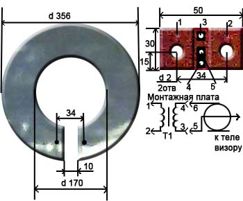
The antenna is an aluminum disk with an outer diameter of 356mm and an inner diameter of 170mm. and 1mm thick, in which a 10mm wide cut is made.
A printed circuit board made of glass lite 1mm thick is installed in place of the cut. This board has two holes for mounting with M3 screws.
The leads of the matching transformer T1 are soldered to the printed circuit board attached to the antenna.
For a transformer, it is best to use a ring core with an outer diameter of 6...10mm and an inner diameter of 3...7mm. and thickness 2...3mm.
The transformer windings are covered with a single-layer insulated wire with a diameter of 0.2...0.25 mm. and have the same number of turns, from 2 to 3 turns. The length of the coil bends is 20mm.
With such a transformer, reception in the meter and decimeter range is possible at a distance of 25...30 km. At a distance of up to 50 km. The antenna works satisfactorily only on deci meter channels.
Without a transformer, the distance of reliable reception is halved.
However, there is a circuit that allows you to get similar results without a transformer; to do this you need to assemble the following circuit: 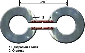
3. Do-it-yourself log-periodic television antenna (UHF).
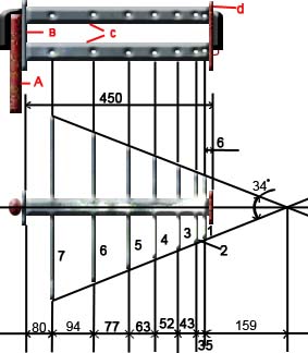

A. Mast
IN. Metal plate (dimensions 87x30x5)
WITH. metal tubes d 16…19mm
D. textolite plate (dimensions 87x30x5)
E. braid
F. coaxial cable
G. central core
7,6,5,4,3,2,1. vibrators
Assembly
1. Take two metal tubes 450 mm long and 16...19 mm in diameter.
2. Make two plates measuring 87x30x5mm. (one is made of metal, the other is made of textolite), drill holes in them, as shown in the pictures.
3. Secure the tubes in the plates (to the metal plate by soldering, and to the textolite plate using screws screwed from the ends of the plate with a diameter of 2.5 mm.
4. In metal tubes, along their length, at the distances indicated in the figure, drill holes with a diameter of 3.3 mm. and cut the M4 thread.
5. Screw 14 directors made from a rod with a diameter of 5 mm into the holes. At one end of each rod, cut an M4 thread to a length of 10mm.
The lengths of the directors, taking into account the part of the length of the threaded end, according to the vibrator number (see figure), are given in the table:
Vibrator No.…..length in mm…..number of pieces
1…………………………..107………………..2
2…………………………..129………………..2
3…………………………..155………………..2
4…………………………..186………………..2
5…………………………..225………………..2
6…………………………..272………………..2
7…………………………..330………………..2
6. Place the coaxial cable in one of the tubes and solder it according to the figure. Paint the solder ends with paint.
7. Attach the antenna to the mast.
Antenna from user Evgen:
1. Take two EMPTY jars - for channels 21 to 41, 0.5 l is better, for channels 42 - 69 - 0.33 l.
2. Fasten them in any convenient way (electrical tape, adhesive tape, rope, glue, etc.) on a solid piece of dielectric (rail, stick, piece of plywood - it is better to paint or varnish the wood, textolite, getinax, etc.) onto at a distance of 10 - 15 mm from each other.
3. We make 2.5 - 4 mm holes in each jar along the edges (as many screws, washers, nuts can be found) and with the help of these we attach the central core of the cable to one jar, and the braid to the other. You can attach any balancing device, but you can do without it.
The receiving distance depends on the installation location of this design (outside is better) and the power of the transmitter.
The holes are on those edges where the jars are closer to each other. And it’s more convenient to first fasten the cable (and the balancing device - if you’re lazy), and then the jars to the supporting structure.
Today, almost all homes are connected to cable or satellite television, and almost all channels are in good quality. But what to do if you are just renting an apartment? Here on help will come a homemade antenna for digital television - as a reliable and inexpensive alternative to a factory one. Read on to see how it is done.
To make this device, you will have to use 550 by 70 mm plywood, several self-tapping screws, and a forty-centimeter copper wire 40 cm long (the central core is 4 mm in diameter).
The base of the product is a board. Next, cut 8 pieces of wire, the length of which is 375 mm, while they should be stripped in the center by 20-30 mm. This is necessary to ensure good contact in signal transmission.
Now, cut out 2 wires, the length of which is 220 mm and, based on the dimensions of the board, they should be cleaned where the connections will be. After this, the remaining wires (eight pieces) need to be bent so that they acquire a “V” shape.

An antenna for digital television is absolutely no different from a regular decimeter antenna.
First, you should start purchasing a special plug, after which it should connect the antenna and cable. This is easy enough. Using a benchtop soldering iron, the plug is attached to the wire. This cable is installed over the bottom connection of the instrument. At this stage, the production of the antenna can be considered completed. It is already ready to be turned on.

An antenna for digital television is absolutely no different from a regular decimeter antenna.
The second method of making a digital television antenna from cans
Here, we will not use a ready-made device as a basis. The device will be completely assembled from available materials. Homemade antenna for digital television is made using:

- wooden trempel;
- adhesive tape or tape;
- soldering iron;
- two tin cans;
- several meters of wire (about 3-5 m);
- plugs.
First, you need to refine the standard TV cable. To do this, you need to slightly cut its soft shell. Under the shell you will see a silvery “foil”. This material covers the cable in several layers. For this reason, in order to see the wire itself, you will have to cut about 10 cm from the edge. After this, you should twist the foil layer in order to make a sample of its middle layer by about 10 mm. The reverse end of the cord is equipped with a plug used to connect to the TV.
We're done with the cable, the banks are next. If we talk about sizes, then a tin container with a volume of 750-1000 mm is enough to receive a digital signal. The end of the wire with the “foil” is attached to one can (otherwise, the display of channels will be incorrect). The cable core is screwed onto the second can. It is preferable to connect the cable and cans by soldering. If the wire is secured with tape, most likely the product will not work.
The only option for using such material is when the cans are installed on top of the trempel. However, here too one cannot deviate from the technology of application. Namely, the arrangement of the cans should form a straight line. Tin containers should be located at a distance of about 7-8 cm from one another.
That's all, the homemade antenna for digital television is ready. Now you can start searching for a suitable signal and securing your device. Such an antenna will allow you to view several channels, up to 10-15, if the signal is not password protected.
Video: homemade antenna for digital television
Digital encoding of the television signal allows it to be delivered to the receiver while minimizing any losses. To support the technology, the TV needs an antenna for DVB-T2. Making such a device with your own hands is much cheaper than buying a ready-made one, paying about 3 thousand rubles for it. Terrestrial digital television displaces all similar types of signal transmission, while offering high-quality broadcasting and a variety of channels.
Changes on air
Making an antenna for an old-style tube TV was considered prestigious in its time and showed the level of skill, in modern world interest in homemade devices does not fade, and many make terrestrial antennas DIY DVB-T2. Manufacturers of industrial equipment adapt to changing reception conditions by connecting modern electronics to standard well-known designs, completely ignoring the fact that the main condition for the operation of the antenna is its interaction with the terrestrial signal.
In recent years, almost all broadcasting takes place in the DVB-T2 range, which reduces the cost and simplifies, from an economic point of view, the antenna-feeder system of transmission stations. Periodic maintenance requires less highly qualified personnel, and their work becomes less harmful and dangerous.
Transmitters television broadcasting They cover all large cities and sparsely populated villages with signals, so catching waves from unattended low-power stations in remote areas becomes important if you install an antenna for DVB-T2 reception, made with your own hands from scrap materials.
Due to the expanded construction of reinforced concrete buildings within the city, the conditions for signal propagation in populated areas have changed significantly. Multi-storey buildings with a metal frame are like mirrors, reflecting waves several times until they are completely attenuated.
There are many TV channels broadcast on the air today. A digital signal differs from others in that it either exists or it doesn’t; there is no middle position. Other transmission systems differ in that the channels perceive interference differently, which reduces their broadcast quality, and sometimes the image may simply disappear. A self-made antenna for DVB-T2 will allow you to receive the same signal for all channels that show the same high-quality picture.
The digital broadcasting signal is special in that it is not affected by interference; if it exceeds noise by one and a half decibels, then good welcome. Signal dropout is affected by cable mismatch or phase distortion at any point in the transmission from the camera to the tuner, and the image can be scattered into small pieces even with a strong signal.
Basic features for making an antenna
Before making DVB-T2 with your own hands, you should study the principle of its operation.

To capture a digital signal, it is required that it can be very simply constructed, even from a simple cable, after making the correct calculation.
The theory says that digital signals are easily broadcast in the UHF range and can be received by any type of antenna, but in reality this does not always work out that way.
You can make a television antenna yourself with minimal costs and without the help of strangers, but it should be remembered that the resulting device is inferior in reception quality to professional devices.
Requirements for antennas
New conditions for broadcasting, distribution and on-air reception have changed the basic requirements that DIY TV antennas must meet. DVB-T2 has abolished the previously significant directional and protective coefficients. In modern devices they do not matter, since the air is polluted, and even small penetrating interference can only be dealt with using electronic means. At the same time, the antenna's own gain (GA) plays an important role.
An antenna that tracks the air well has a power reserve for the received signal, which allows the electronics to sift it from interference and noise. A modern antenna for DVB-T2, made with your own hands, preserves electrical parameters in a natural way, and does not adapt to acceptable parameters using engineering techniques. It is coordinated over the entire operating frequency range without the use of balancing devices.
Antenna amplitude and frequency characteristics
The antenna is made as smooth as possible; phase distortions arise due to sharp emissions and dips. Single-frequency antennas are stretched to an acceptable noise-to-signal ratio, thus allowing them to receive up to 40 channels. But matching amplifiers are additionally installed to them, which absorb waves or distort phase indicators.

Most effective digital antenna DVB-T2 is made by hand:
- frequency-independent - with low performance, but cheap and easy to manufacture, designed in a short period of time, designed for reception in relatively clean air at a short distance from the transmitted station;
- periodic band, catching all waves in space, ideally sorting them, which has a simple design, ideally works in tandem with a freeder throughout the entire reception range.
If we talk about design, the simplest DVB-T2 antenna is made by hand in the “eight”, “Polish” and “square” versions.
Figure-of-eight antenna
Refers to easily constructed devices, made like a standard figure eight, from which the reflector is removed. The ideal material is an aluminum strip, corner, tube, tire, or other profile. Top size 140 mm, side length 130 mm, but these dimensions are given as a guide; during manufacturing they should not be kept exactly to the millimeter.
To begin with, cut a wire 112 cm long, begin to bend the first part 140 mm long, of which 130 mm goes to the antenna, and 10 mm remains for the loop. The next two sections are bent equally to a length of 140 mm, the next two - 130 mm, the next pair - 140 mm, then another 140 mm, then - 130 mm and make a second loop. The connections are pre-cleaned, connected and soldered; they are also contacts for fastening the cable core.
Stripping the cable and plug is done using a scalpel and a file. After soldering, the joints are sealed and secured with glue from a hot gun. If we talk about the plug, then the glue is poured into the solder joint, then into the cavity of the cap, the excess is then removed. The joint is assembled so quickly that the adhesive mass does not harden. The result is an eternal, strong and elastic connection. To make contact, we strip the ends of the cable from the plug side by 1 cm, from the antenna side by 2 cm.
When connecting by soldering, a do-it-yourself indoor digital DVB-T2 antenna is also sealed with glue, where it is recommended to install a rigid frame at the point of contact according to the size of the joint. If the device is made for yourself and will be rigidly fixed during operation, and transfer is not needed, then the frame is not made. A device made of this type easily picks up digital signals in the line of sight TV tower at a distance of up to 10 km when installed outdoors.

Using a “Polish” antenna
The “Polish” antenna received its name during the times of the former Soviet Union as a reliable device for receiving signals from Soviet television, as well as channels in the UHF range. Digital broadcasting is practically not received on it due to its low efficiency. Some amateurs are trying to bring the design to ideal by shortening the long decimeter mustache and removing the reflector. Such a change in some cases allows you to adjust the image in digital format, but talking about guaranteed receipt there is no reliable result. Speaking about Polish devices, we can note the high-quality operation of the amplifier, which works effectively with a digital signal.
Antenna type "square"
This DIY indoor DVB-T2 antenna is a modified copy of the standard design, known as “three squares,” which has six components and a matching transformer. A homemade antenna of this type confidently copes with the reception of TV channels digital format up to 10 km in a straight line, longer distances require a signal booster.
The antenna design is simple to implement. The main structural element consists of round aluminum wire and single-core wires. The wire is bent to obtain six squares and a matching tap is made, which is a transformer high frequencies so that the signal matches the cable and the DVB-T2 antenna with the amplifier. With their own hands they solder the wires to the points, wrap them with copper wire and tin them with a soldering iron.
The cable is attached to the antenna with special clamps or using ordinary insulating tape. The cable is connected by placing a support, using a wooden plank or other material. When installing indoors or outside a building, the main condition is precise alignment with the television tower. This is done using a navigator; if there is no line of sight, the direction is clarified until the effect of receiving a powerful signal.
Antenna made from beer cans
The technology for manufacturing such an effective antenna is very simple and does not require special skills.

Using a thick awl or screwdriver, make neat holes in the neck of each of the two cans, then screw screws into them. The cable ends are freed from the braid, the copper wires are cleaned of varnish with a knife, and they are attached under the screw heads. It is very good to solder the resulting connection, but not necessary.
The DVB-T2 digital antenna is almost made with your own hands; it remains on the prepared rail or pipe to secure the cans so that there is a distance of 7.5 cm between them. The second cable end is equipped with a standard plug that is connected to the receiver; the device is installed in the place where the signal is best recorded. Placing this type of device outdoors requires reliable protection from bad weather. This is done with any waterproof material, often plastic bottles are used. large size. The antenna receives up to 15 channels satellite television and digital broadcasting.
Using Instruments and Amplification
At a certain distance from the television tower, the antenna is capable of receiving signals without installing additional amplifying devices. To receive a signal from greater distance stocked with a wave amplifier with separate power supply. The device is installed near the tuner, and the matching device is made additionally; for its manufacture you need:
- potentiometer for gain adjustment;
- standard decoupled throttles L4 and L3;
- coils L2 and L1 are wound according to dimensions from the directory;
- a metal screen to separate the output circuits from the device circuit.
The amplifiers are placed no further than 3 meters from the place where the DVB-T2 cable antenna is installed, which receives power from its own unit with its contacts. When installing an antenna near a broadcasting tower, it is not recommended to use an additional amplifier, since a strong signal degrades the image and has an additional effect on the entire structure. The recommended cable length is three meters; a larger wire will lead to imbalance of the balun.

Application of a symmetrizer
This device is needed for any type of antenna, and it does not matter whether it was made at a factory or in a craftsman’s workshop. Antenna for DVB-T2, made by yourself, gives good quality images when connected to a tuner. If the cable length is more than 10 m, then when installed outside the building, inconsistencies in the resistance of the external space and the cable arise. In this case, it is necessary to use a symmetrizer in a comprehensive antenna solution, which greatly improves the quality of the image on the screen.
Cable laying and antenna installation
The main rule is to install the antenna at a height. If this cannot be done in the room, you need to move the device to an external wall. To install an antenna in a private building, digital broadcasting operators rely on a device height of 10 m. If the antenna is located on the ground floor of a house, then nearby metal structures and industrial objects cause poor reception.
When placing the antenna under a canopy or the roof of a house, pay attention to the roofing material - it should not contain a metallized coating or spraying. Metal tiles, corrugated sheets, iron or foil insulation create significant interference with the reception of digital television signals.
For high-mounted receiving antennas on a metal mast or pin, a steel rod of at least one meter in size is provided, to which a grounding wire is connected. The device located on the roof is included in common system grounding of the house.
The cable is not routed through smoke and ventilation ducts, and is not hung on existing electrical wires, even if they look more than reliable. The holes in the walls are placed at an angle so that moisture from the street does not flow into the room; special commercially available plugs are used. If the antenna is made well and correctly, take the cable and wall sockets high quality, since after the final finishing of the walls it is difficult to redo the cable in the wall and replace it with a more reliable one.

Compliance with safety precautions when installing the antenna
Before installing or adjusting an already mounted antenna at a height, make sure that this action is safe:
- do not climb onto weakly secured and shaky structures; if working at height is associated with danger, be sure to wear a mounting belt and attach it to a fixed part of the building structure;
- The assistant is not allowed to hold the end without first securing it; if he falls, the assistant will not be able to hold his body weight in his hands;
- It is forbidden to climb to a height alone, when structures are icing, to walk on an old roof, or to step on connecting seams;
- Do not install the antenna in rain or fog.
In conclusion, it should be said that it is quite easy to do it yourself receiver in order to watch digital television. DVB-T2, a home-made antenna, is almost as good in quality (if you follow the right technology) as store-bought counterparts. The cost of materials will allow you to save a decent amount of money, which is important for some people.