DIY miniature sound amplifier. How to make a sound amplifier with your own hands using improvised materials
Somehow, at one fine moment, I finally got tired of the wheezing, grunting and wild distortion from not serious computer speakers. I went through several options, but unfortunately none of them satisfied me either in terms of sound quality, functionality, and, most importantly, design. In general, I had to remember my youth when I was an avid radio amateur and try to do something useful myself...

Power sound amplifier 2x25W, made on TDA 7265 chips - this is the main amplifier, TDA 1517 is a 2x5W headphone amplifier, these are the main ones. Its superiorities are of course obvious, at least in terms of output power. But I made it not only for the ears, similar copies that are on sale do not meet my needs at all....including in terms of ease of use. For example, to connect headphones with a thick 6.3 mm Jack plug is a whole epic with adapters and other nonsense, not to mention the fact that they cannot fully pump up such headphones with decent quality. The appearance of purchased products leaves much to be desired, and you want to put such boxes under the table so that you never see them, where it is inconvenient to turn them on, this amplifier is free of this drawback, because it turns on and off synchronously with the computer. All backlighting is turned off with a button on the back wall so as not to interfere with using the computer in the dark; after the next turn on, it automatically turns on again. Buttons on the front panel "NETWORK" and turning off and turning on the speakers.

Amplifier electronics
In fact, all electronic small items were found at home; only amplifier microcircuits and switches with headphone jacks were specially purchased. I made and developed the boards myself, except for the one for the indicator, I found this one on the Internet. Since I already have some experience in building electronic devices, this was not particularly difficult for me. Even I would say it was interesting to remember my youth.

The radiator was found in the bins of some old sound amplifier. I had to castrate it a little (it was too big), but after a long run at maximum power I was satisfied with the result. The heating is not critical, I would even say not very strong, and this despite the fact that I placed power stabilizer chips for the amplifier on the same radiator. In the photo they are now visible. There are 7 pieces in total, one holds 1A and together it turns out to be 7A. The power-hungry amplifier showed a current consumption of 5A during measurements.

The amplifier will be located here, the screen is specially made of tin in order to exclude interference and interference from power stabilizers (the current is not small, but the amplifier turned out to be very sensitive and I decided to play it safe).

Mounted, the TDA 7265 microcircuit, the circuit is assembled on a dashboard with minor modifications for your needs, beats honest 2x25W not HI-END of course, but for the computer to keep the ears happy, it’s quite enough, after all, if you want something more serious, the computer has a digital output, and it You can connect to the receiver. The relay switches the speakers (the button on the panel only turns on the relay). This is not unreasonably due to the fact that the contact of the relay is more reliable than that of the switch. I know this from my own experience...

A separate small amplifier with a power of 2x5W was made for the headphones, a little too big in power, of course, but it will pump up any headphones 100%, listening to powerful large headphones left a positive impression, the microcircuit heats up quite strongly at high volumes, so then during final assembly I’m thinking of sticking a small radiator from sin. I made a separate amplifier because I did not want limiters such as resistors, etc., to be present in the audio path. which would have to be installed if we took the signal from the main amplifier. And here the signal, immediately after amplification, goes to the sound emitters without limitation, which certainly has a positive effect on the quality.

This is a simple circuit for controlling an output power indicator... I found it on the net by accident, at first I wanted to assemble it on a K157DA1 microcircuit specialized for this, but unfortunately running around radio stores did not give any results and I made the circuit using transistors. The circuit is from some Soviet tape recorder...

This is the power distribution board. It also has relays for switching power (I didn’t bother with electronic keys and decided to take the easy way). Stabilizers on a homemade radiator 12V to power the headphone amplifier and a second one at 5V for LED backlighting.

Set of parts for power supply. A case from some printer found in “useful things” at home, the transformer was given by a friend (by the way, special thanks to him, despite its small size, when dialing it showed unexpected results: at 25V it consistently output 10A without heating!!!) Also in the photo The starter relay from the car stands out. Also found at home, they are supposed to turn on the amplifier using a computer. We take 12V from the computer and voila.. This is so as not to worry about turning the amplifier on and off every time, it will be controlled from the computer and work synchronously with it. For normal work without a computer, I will put a switch on the back wall that short-circuits the relay contacts and excludes it from the circuit.

The installation of the power supply turned out to be very tight.
Amplifier indicator
I wanted to make the indicator similar to the indicators of the famous amplifiers of my youth. Inspired by memories of turbulent times, he began to work.

The stylish indicator that I would have liked was not possible to purchase. It was decided to perform it myself, using specially purchased Chinese testers. Milliammeters were removed from them, the red arrows were repainted black.

The body was made from whatever came to hand in the pile of rubbish on the balcony.

The scale was drawn in the Front Designer program, with subsequent modification in Corel Drav, because the first one does not work well with different fonts, but it was necessary to write it in a more interesting way.

The protective caps for the mechanical parts of the indicator are made from the necks of beer bottles, successfully used along the way.

The general picture of the future product is already emerging.

Trying on indicators. Then they are put away until the final assembly of the device (very delicate parts, they can easily be damaged).

For control, a voltage amplifier is soldered so that there is no influence on the audio path and the operation is correct. We check - everything is fine, it works perfectly. The circuit was found on the network from some Soviet Soviet tape recorder, I don’t remember Spring.

Let's see how the backlight turned out, plexiglass light guides are glued together, LEDs are glued into them, nothing unusual.

Here is the scale, the inscription mr. Kolesov is my last name, I won’t die of modesty... and I wanted to make some kind of name... copying some brands is stupid in my opinion. And it’s so unusual, and you can pin your friends...
Volume control
Of course, I wanted to make a classic regulator, a big round one, definitely not a push-button one... So that when you touch and rotate, you feel like you are moving a thing, and not some toy Chinese junk... On the encoder, the adjustment disappeared by itself, I needed a position light on the handle, but you won’t be able to rotate it endlessly with a wire. In general, I didn’t bother and decided to do it with a variable resistor. In the end, if it starts to creak, change it within 5 seconds.
And so to your attention - another perversion...

While crawling around the house I came across a tube of cream. After negotiations with my wife, she presented me with a lid from him for later tearing apart. As planned, there was a backlight on the handle so that the position of the regulator could be easily and quickly determined (this is especially true in the dark). A 1mm hole was drilled, and I will attach a light behind it later.
A handle from some old tape recorder or receiver (found in the bins) was glued into the middle of the epoxy; it fit the variable resistor like a native one.
We put an LED on the epoxy, having previously covered it with foil (it is very bright, I didn’t want it to shine through the walls of the handle), at the same time the excess resin leaked into the hole formed a kind of light guide, the smudges are sanded off and the surface is completely smooth, it’s very difficult to guess where the hole is until you light it little light

After hardening, we check for strength how this supposed bushing sits... everything is cool and strong... we can continue further.

I decided to paint the inside with silver paint (varnish with aluminum powder), it seems to me that there will be some kind of reflective effect, although I didn’t notice any difference. Having soldered the wires and the quenching resistor, I filled the whole thing with epoxy, leaving a little space for the wires to move freely during operation. The handle has acquired rigidity and weight... monolithic... Also painted with silver.
Sanding with fine sandpaper so that the paint does not peel off later. It will hold on to a rough surface normally, despite the fact that it is polyethylene and practically cannot be painted. First coat of paint. Turn on the light and admire the result. I was pleased.

The scale was made in the Front Designer program, and the inscription and symbols were made in Corel Drav. In a designer, you won’t have enough options.

The scale printed on glossy paper is placed between 2 sheets of organic material, everything is connected for subsequent stages of work.

LEDs are glued into the ends for illumination and everything is painted so that the light does not scatter throughout the body and does not illuminate neighboring elements... for example, the indicator is illuminated with white light and you would not want the light to be mixed.


Contact panel
There are a minimum of switches and connectors, only the essentials. Why does a power amplifier need extra bells and whistles? All settings are in the computer's sound card.
Switch "Network". The speaker switch, the signal to the headphones is constant, regardless of whether the speakers are turned on or not - this is also part of the intended plan. Nowadays you won’t find an amplifier with such a circuit, even serious receivers are made according to the principle “plug in headphones and there is no signal to the speakers,” but before everything sound amplifiers were made exactly according to the same scheme as I did. I don’t know if it’s convenient for someone and vice versa, but for me this signal distribution scheme is very relevant.

The holes for the switches were selected using wood bits. Also, a crown of a larger diameter was used for the skirt around the hole in order to highlight the switches with backlighting (the scratched and untreated surface of the organic material refracts the light).

Headphone jacks are also installed. And be sure to have different diameters Jack 3.5 mm and Jack 6.3 mm so that later you don’t have to worry about all sorts of adapters. What kind of plug do the headphones have with this one and you can easily plug it in without any problems.

Painting first with silver to distribute the light evenly and then with paint so as not to highlight everything around the panel.

4 lights and here is the final result, there is also an LED inside the headphone jacks for the overall picture.
Frame
I had to tinker with the body, but since this is the face of the product, it was worth it.

The chipboard was found again in a pile of rubbish on the balcony, left over from some old furniture and left as a useful thing and could come in handy, which is exactly what happened.

Having cut the parts to size, I screwed everything together with self-tapping screws.

Before assembly, I coated the joints with glue for reliability.

I cut holes for installing control and display elements.

Raw edges don't look very good. The ends were processed using a manual milling cutter.

I had to process it in several passes to get perfect uniformity of all edges.

To secure the rear wall, bars were installed; a large indentation from the edge was made in order to hide the cooling radiator and all wire switching elements, etc. Due to this, the amplifier can be placed close to the wall.

The stages of puttying and painting have been completed, puttying was done with polymer putty with the addition of PVA glue for good retention on the surface, primer after each layer, of course. Painting with NC paint and then varnishing with NC varnish. Subsequent polishing of the coating with polishing paste and finishing polish for the car body.

The result was a beautiful polished surface, which turned out cooler than on a grand piano.
Legs
It was decided to make the supports for this product in the classic design style of radio equipment - chrome-plated, but with a slight twist ala UFO. Blue lighting was planned at the base of the legs.

It was made from what was also found on the balcony in a pile of rubbish. Chromed furniture pipe 25mm, organic 3mm (fitted by a friend), lights of course, I went and bought + glue (superglue and epoxy resin).

The blanks are cut, glued and lights are glued into them, incorrectly for transmitting the luminous flux, but more on that later..

A round-shaped organic layer is provided so that later, when pouring, the epoxy does not leak out.... The pipe blank is tightly placed on the base.

Glue is poured into the molds, and the parts await further processing after the resin has hardened.

The semiconductor element itself is initially secured with hot-melt adhesive....

The parts are dry. Processing completed. Excess plexiglass was removed, the edges were carefully sanded so as not to spoil the chrome on the metal part of the leg.

At the final stage, rubber gaskets were made from a bicycle inner tube.....aluminum foil was glued to the gasket on the inside, (to reflect light) everything was glued together for a transparent moment.

The assembly is complete, it's time to see what happened.

It didn't turn out bad. Basically, what I wanted, everything worked out.
They are becoming a thing of the past, and now, in order to assemble any simple amplifier, you no longer have to struggle with calculations and riveting a large printed circuit board.
Now almost all cheap amplification equipment is made on microcircuits. The most widespread are TDA chips for amplifying audio signals. Currently used in car radios, powered subwoofers, home speakers and many other audio amplifiers, they look something like this:


Pros of TDA chips
- In order to assemble an amplifier on them, it is enough to supply power, connect speakers and several radio elements.
- The dimensions of these microcircuits are quite small, but they will need to be placed on a radiator, otherwise they will get very hot.
- They are sold at any radio store. There are some things on Ali that are a little expensive if you buy them at retail.
- They have built-in various protections and other options, such as muting the sound, etc. But according to my observations, the protections do not work very well, so microcircuits often die either from overheating or from. So it is advisable not to short-circuit the terminals of the microcircuit with each other and not to overheat the microcircuit, squeezing all the juices out of it.
- Price. I wouldn't say they are very expensive. In terms of price and functions, they have no equal.
Single-channel amplifier on TDA7396
Let's build a simple single-channel amplifier using the TDA7396 chip. At the time of writing, I took it at a price of 240 rubles. The datasheet for the chip said that this chip can output up to 45 Watts into a 2 Ohm load. That is, if you measure the resistance of the speaker coil and it is about 2 ohms, then it is quite possible to get a peak power of 45 watts from the speaker.This power is quite enough to arrange a disco in the room not only for yourself, but also for your neighbors and at the same time get mediocre sound, which, of course, cannot be compared with hi-fi amplifiers.
Here is the pinout of the microcircuit:

We will assemble our amplifier according to a typical diagram, which was attached in the datasheet itself:

We apply +Vs to leg 8, and nothing to leg 4. Therefore, the diagram will look like this:

Vs is the supply voltage. It can be from 8 to 18 Volts. “IN+” and “IN-” - we send a weak sound signal here. We attach a speaker to the 5th and 7th legs. We set the sixth leg to minus.
Here is my wall mounted assembly

I did not use capacitors at the power input of 100 nF and 1000 μF, since I already have pure voltage coming from the power supply.
I rocked the speaker with the following parameters:

As you can see, the coil resistance is 4 ohms. The frequency band indicates that it is a subwoofer type.
And this is what my sub in a self-made housing looks like:

I tried to shoot a video, but the sound on the video is very poor. But I can still say that the phone at medium power was already hammering so hard that my ears were turning, although the consumption of the entire circuit in working form was only about 10 watts (multiply 14.3 by 0.73). In this example, I took the voltage as in a car, that is, 14.4 Volts, which is well within our operating range from 8 to 18 Volts.

If you do not have a powerful power source, then you can assemble it according to this diagram.
Don't get hung up on this particular chip. These TDA chips, as I already said, there are many types. Some of them amplify the stereo signal and can output sound to 4 speakers at once, as is done in car radios. So don’t be lazy to scour the Internet and find a suitable TDA. After completing the assembly, let your neighbors check out your amplifier by turning the volume knob all the way up to the balalaika and leaning the powerful speaker against the wall).
But in the article I assembled an amplifier using a TDA2030A chip

It turned out very well, since the TDA2030A has better characteristics than the TDA7396
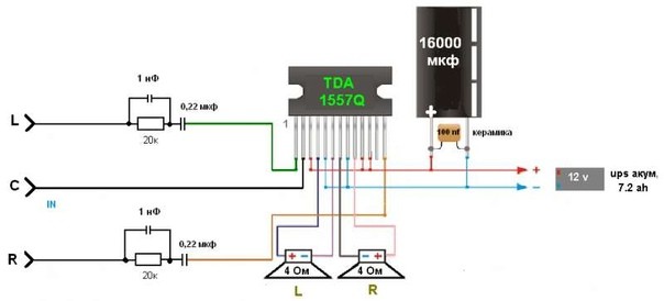
For variety, I’ll also attach another diagram from a subscriber whose TDA 1557Q amplifier has been working properly for more than 10 years in a row:
Amplifiers on Aliexpress
I also found kit kits on Ali on TDA. For example, this stereo amplifier is 15 watts per channel and costs $1. This power is quite enough to hang out in your room listening to your favorite tracks.

You can buy it.
But it's ready right away

And in general, there are a lot of these amplifier modules on Aliexpress. Click on this link and choose any amplifier you like.
It will have different dimensions and circuit design complexity. The article will touch upon three types of amplifiers - transistors, microcircuits and tubes. And it’s worth starting with the latter.
Tube ULF
These can often be found in old equipment - televisions, radios. Despite its obsolescence, this technique is still popular among music lovers. There is an opinion that tube sound is much cleaner and more beautiful than “digitized” sound. It is quite possible, in any case, that the same effect as from lamps cannot be achieved by using transistor circuits. It is worth noting that the audio amplifier circuit (the simplest one, using tubes) can be implemented using only a triode.
In this case, it is necessary to send a signal to the radio tube grid. A bias voltage is applied to the cathode - it is adjusted by selecting the resistance in the circuit. A supply voltage (over 150 Volts) is supplied to the anode through a capacitor and the primary winding of the transformer. Accordingly, the secondary winding is connected to the speaker. But this is a simple circuit, and in practice two- or three-stage designs are often used, in which there is a preliminary and final amplifier (using powerful tubes).
Disadvantages and advantages of lamp designs
What disadvantage can lamp technology have? It was mentioned above that the anode voltage should be over 150 Volts. In addition to this, it is necessary to have an alternating voltage of 6.3 V to power the filaments of the lamps. Sometimes 12.6 V is required, since there are lamps with this filament voltage. Hence the conclusion - there is a huge need to use massive transformers.

But there are advantages that distinguish tube technology from transistor technology: ease of installation, durability, and it is almost impossible to damage the entire circuit. Unless you need to break the lamp cylinder to break it. The same cannot be said about transistors - an overheated soldering iron tip or static can easily destroy the junction structure. The same problem exists with microcircuits.
Transistor circuits
Above is a diagram of an audio amplifier using transistors. As you can see, it is quite complex - a large number of components are used that allow the entire system to work. But if you break them down into small components, it turns out that not everything is so complicated. And the whole circuit works almost the same as the one described above on a vacuum triode. Essentially, a semiconductor transistor is nothing more than a triode.

The simplest design is a circuit on a single semiconductor, the base of which is supplied with three voltages at once: from the power supply positive through a positive resistance and from a negative common wire, as well as from the signal source. The amplified signal is removed from the collector. Above is an example of an audio amplifier circuit (the simplest one using transistors). It is not used in its pure form.
Microcircuits
An amplifier based on microcircuits will be much more modern and of higher quality. Fortunately, today there are a great many of them. The simplest audio amplifier circuit on a microcircuit contains an extremely small number of elements. And anyone who knows how to handle a soldering iron more or less tolerably can make a good ULF on their own. As a rule, microcircuits contain a couple of capacitors and resistances.

All other elements necessary for operation are present in the crystal itself. But the most important thing is nutrition. Some designs require the use of bipolar power supplies. Often the problem arises there. Microcircuits that require such power, for example, are quite difficult to use to make a car amplifier.
Useful gadgets
Since we have already started talking about amplifiers on microcircuits, it would be worth mentioning that they can be used with tone blocks. Microcircuits are produced specifically for such devices. They contain all the necessary components; all that remains is to correctly install the entire device.
And you will have the opportunity to adjust the timbre of the music. Together with the LED equalizer, this will be not only convenient, but also a beautiful means of visualizing sound. And the most interesting thing for car audio lovers is, of course, the ability to connect a subwoofer. But this is worth devoting a separate section to, because the topic is interesting and informative.
Subwoofer made easy
Advantages of modern amplifiers on microcircuits
Having considered all possible types of amplifiers, we can conclude: the highest quality and simplest ones are manufactured only on modern element base. A lot of microcircuits are produced specifically for low-frequency amplifiers. An example is the ULF type TDA with different digital designations.
They are used almost everywhere, as there are both low-power and high-power chips. For example, for portable computer speakers, it is best to use microcircuits with a power of no more than 2-3 W. But for automotive equipment or home theater acoustics, it is advisable to use microcircuits with a power of over 30 W. But pay attention to the fact that they need sound protection. The circuits must contain a fuse that will protect against short circuits in the circuit.

Another plus is that a massive power supply is not required, so you can easily use a ready-made one, for example, from a laptop, PC, old MFP (new ones, as a rule, have the power supply inside). Ease of installation is what is important for beginning radio amateurs. The only thing required for such devices is high-quality cooling. If we are talking about powerful equipment, then you will have to install a forced one - one or more coolers on the radiator.
Sometimes connecting speakers to a TV, laptop or other similar music source requires signal amplification through a certain device. If you have basic technical knowledge, you can make an amplifier at home with your own hands.
How to create a sound amplifier correctly
First of all, to assemble such a device for speakers, you will need tools, as well as the required components. Circuits of the simplest amplifiers are assembled using a soldering iron mounted on a support with a high degree of stability. It is advisable to use certain soldering stations.

In the process of assembling an amplifier with your own hands for testing the corresponding circuit, or using it for a short period of time, a model on a wire would be a good option, but it will require a lot of free space to arrange the component elements.


The printed circuit board guarantees maximum compactness of the device and convenient use in the future.

A popular and affordable amplifier, intended for headphones or small speakers, is made on the basis of a microcircuit that represents a small-sized control unit with a built-in set of commands for controlling the electrical signal.

A pair of resistors and, of course, capacitors should be connected to the circuit with the desired microcircuit. In total, the price of an amplifier assembled by yourself will be much lower than the cost of equipment purchased in a specialized store, while the limitation of functionality is changing the volume of the signal.

Do not forget about the features of single-channel amplifiers, the independent production of which is carried out on the basis of both TDA circuits and their analogues.

The circuit generates a lot of heat during the working process; it is for this reason that its contact with the elements of the device should be minimized. A radiator grille designed for heat dissipation is desirable for use.


Depending on the purchased microcircuit, as well as the power of the device, the size of the required radiator increases. When assembling the amplifier inside the housing part, you need to think in advance about the space provided under the heat sink.

Another feature of creating an amplifier with your own hands, as shown in the photo, is the minimum power consumption, which makes it possible to use a simplified amplifier in cars, on the road, or at home. Some simple amplifiers require only a few volts.

The power consumed directly depends on the required level of signal amplification. The audio amplifier from the player used for the required headphones consumes approximately 3 W.

To make circuits, it is better for an inexperienced radio amateur to use a special program for which the files have the required extension.

Creating the necessary circuit yourself is possible if you have certain knowledge and the desire to experiment with it. Otherwise, it is better to download files for quickly assembling a replacement amplifier of the lowest possible frequency.


For laptop
The instructions on how to make an amplifier for a laptop with your own hands provide for assembling such a device in the following cases: the built-in speakers are broken or have low volume quality.

You will need a regular amplifier with a power of several watts and a winding resistance of 40 ohms. In addition to the usual tools, assembly requires a printed circuit board, power supply and microcircuit. Choose your own housing where the amplifier elements will be located.

The assembly process should depend on the downloaded chip format. The radiator is selected in such a way that thermal conductivity makes it possible to maintain the required temperature regime of the microcircuit.

If the device is constantly used along with a laptop outside the room, then it will need a self-made case with certain slots or holes so as not to impede air circulation.


Such a case is assembled from a plastic container or the remains of failed equipment, and the board is secured with screws.

Tube amplifier
This DIY amplifier, as in the photo, is a fairly expensive device if you buy all the components.

Some radio amateurs have lamps and other necessary parts in stock. Assembling a tube-type amplifier at home is considered not a difficult task if you can spend time searching for the necessary circuits on the RuNet.

If you need to find out what types of amplifiers there are, it is important to understand that their circuit in each individual version is unique, and also depends directly on the sound source, size, and other important parameters.

Photos of DIY amplifiers


Amplifier with HI-END sound quality
We present to your attention an amplifier with a very soft sound, like a tube amplifier, but superior to tube amplifiers in other parameters (signal-to-noise ratio and non-linear distortion).
Reproducible audio range: from 10Hz to 25kHz
Signal-to-noise ratio: no less than 92dB (not weighted)
Harmonic distortion: 0.001%
What pushed me to create such an amplifier was my love for very good and high-quality sound.
After reviewing a lot of various circuits, I made a small sketch of the circuit diagram of the amplifier. Later I came across a search for a good-sounding operational amplifier, and it took about 2 weeks to search for a microcircuit on the Internet at that time.
The first condition is that this operational amplifier must be high-voltage, the second is that it has a very high-quality signal-to-noise ratio. Before that, I assembled good amplifiers using domestic element base chips K544UD2 and K574UD1, as well as powerful output transistors KT818 and KT819. At that time, their parameters completely suited me.
But with the advent of modern imported equipment on our shelves, the requirements for such an amplifier became much higher; we wanted very high-quality sound, comparable in sound to tube amplifiers.
So, I decided on all the components, the actual assembly of the amplifier itself began, and since at that time I was working in a service center, I did the setup and assembly at work in my free time from repairs.
The first version of the amplifier looked like this - it was just the beginning.
Since at that time I did not yet have either a case or completely wired boards, the device was assembled in a box from DVD player packaging. It worked in this form for about a month, and no incidents occurred during the work.
After that, I took up the PCB layout and this is what came out of it.


Well, what do industrial production boards look like:

The amplifier circuitry is quite simple to assemble and does not contain scarce elements.
All components can be purchased at any radio market.
The classic circuit design of both the input and output stages made it possible to create a very easy-to-assemble amplifier circuit and, importantly, there is no need to configure it. Yes, it does not need adjustment, since the circuit does not contain regulatory elements for adjusting the quiescent currents of the output stage, a thermal stabilization system, etc.

After assembling the amplifier, it is necessary to check the DC voltage at the amplifier output after connecting it to the network; it should be in the range of +20/-20 mV, while the amplifier input must be shorted to ground. If this voltage is within normal limits, the amplifier is ready for operation, just remember to unsolder the jumper at the input.
The operational amplifier contains a voltage amplification circuit with a gain of approximately 25. Transistors VT1, VT2, VT5, VT6, VT7 and VT8 are connected according to the OE circuit and act as current amplifiers with a gain of 10.
The thermal stabilization circuit of the amplifier itself is assembled on transistors VT3 and VT4, and they, like the output transistors, are also located on the radiator. If these transistors are not mounted on a radiator, the amplifier will instantly heat up to a temperature of over 90 degrees.
The maximum heating temperature of the amplifier under load and long-term operation was 70 degrees.
Coil L1 contains from 16 to 20 turns of 1mm PEV-2 wire wound in one layer.
It is advisable to use metal-paper capacitors C2 and C7, and multilayer ceramics for the rest.
Transistors can be used imported, suitable for the parameters.
With certain changes in the circuit, the power of this amplifier can be increased to 100W.
Below is a photo of the assembled amplifier:


Unfortunately, I am not a metal and wood craftsman, but this is what I got out of it.
This amplifier has been working quite reliably for 8 years and no problems have occurred. Its sound quality is very decent, in some ways superior to tube amplifiers in terms of softness of sound, not to mention the noise and nonlinear distortions of the tube amplifiers themselves. Yes, yes, I didn’t make a mistake.
Comparisons were made in terms of sound quality with such models as NAD, Rotel, Arcam and Yamaha, this amplifier circuit surpassed all of the above models in softness and sound quality.
There are two options for boards for the left side and the right side; only the left side of the board layout is in the archive.
|
What do you think of this article? |