Download the color scheme. Color music consoles. What do we need
This color music scheme is a typical analog color music set-top box, like those that were very popular in the 80-90s, and, in my opinion, are undeservedly forgotten today.
The input signal is fed through a separate transformer to eight active filters, which divide the signal into eight frequency channels. The presence of a transformer ensures galvanic isolation of the set-top box from the audio equipment working with it. At the outputs of the filters, rectifiers are turned on, generating a constant voltage proportional to the signal magnitude in the operating band of the given filter. This voltage is supplied to the gate of the thyristor and, having reached the required value, opens it.
Now more details. The signal from the ULF output enters the color music circuit through the isolation transformer T1. This transformer uses a choke on an W-shaped core with two windings. The windings are the same, with low resistance (200-300 turns each). Similar chokes are used in many power supplies for household television, video, audio, and computer equipment. The choke is ready-made, but if necessary, you can wind it yourself.
Since the T1 windings are low-impedance, you need to connect the SMU input to the UMZCH output, that is, in parallel or instead of the speaker system, or to the telephone output for connecting headphones (if this does not automatically turn off the main speaker systems). If you need to supply a signal exclusively from the linear output of the equipment, you need to make an additional UMZCH to work with a light and music set-top box, for example, based on the popular K174UN14 microcircuit or any other UMZCH.
Without a transformer, it is impossible to send a signal to the input of the color music circuit because the lamps are controlled by thyristors, and the entire color music circuit ends up under mains potential, which can lead to both electric shock through the audio equipment and damage to the audio equipment.
Trimmer resistor R1 is used to generally adjust the signal level. Plus, in front of each bandpass filter there is its own additional regulator (resistors R2-R9), which regulates the signal level in its frequency channel. With the help of these resistors, you can adjust the sensitivity of the channels depending on your desire; you can practically say that they regulate the “color timbre,” so to speak.
All active filters are built using the same bandpass filter circuits. They highlight bands with central frequencies labeled on the diagram. The average band frequency of each filter depends on the capacitances of the two capacitors, which must be the same. Otherwise, all the ratings of the filter parts are the same.
The filters are made on operational amplifiers, and they, as you know, require bipolar power supply. Unfortunately, in the chosen power supply circuit, organizing bipolar power supply, although possible, is still problematic. Therefore, it was decided to power the op-amp from a unipolar 12V source, and in order to ensure their normal operation, apply half the supply voltage, obtained using a voltage divider R40-R41, to the positive input.
Thus, in the color music circuit there are eight operational amplifiers, namely two LM324 microcircuits containing four operational amplifiers each. 
After the op-amp, the signals from the selected bands are sent to diode detectors, each with two diodes connected according to a voltage doubling circuit. At the output capacitors (C4, C8, C12, C15, C19, C23, C27, C31) of these detectors, a constant voltage is released, which is supplied to the control electrode of the thyristors. Initially, it was planned to connect one resistor with a resistance of 10-50 kOhm in parallel to each of these capacitors, but during setup it turned out that when using MCR106-8 thyristors there is no need for this. And these resistors were removed from the color music circuit. Therefore, there are no resistors with position designations R13, R17, R20, R24, R28, R32, R35 and R39 in the diagram. If you use other thyristors that may “not want” to close, these resistors will have to be returned to their place (some were connected in parallel with capacitors C4, C8, C12, C15, C19, C23, C27, C31), and their resistances should be selected experimentally .
When using MCR106-8 thyristors, the maximum load power of each channel can reach 900W. At powers up to 200W, a radiator is not required, but at higher powers it is needed, since the thyristors will overheat.
Output stages can be made using other circuits, for example, using optosimistors. In this case, the voltages from capacitors C4, C8, C12, C15, C19, C23, C27, C31 must be supplied to the bases of additional transistor switches, in the collector circuits of which the LEDs of the optosimistors will be turned on (through the necessary current-limiting resistors). By the way, if in this case the “electronics” are powered from a 12V source made on a transformer, then in this case, there is also no need for an input transformer, and the signal can be supplied from the linear output of the equipment directly to R1. 
The op-amp power supply is made according to a transformerless circuit using diodes VD17-VD18, capacitors C32 and SZZ, as well as a zener diode VD19 (zener diode for voltage 12V and power 1W).
Everything except the thyristors is assembled on one printed circuit board made of single-sided foil fiberglass. There is one jumper on the board.
Based on the same color music circuit, you can make a color music device operating from a 12-volt source (for example, a car on-board network), and the screen can be made from multi-colored super-bright LEDs. The following figure shows a four-channel version of the color music circuit. Of course, you can make eight channels, but in terms of color there are only four types of LEDs on the market - red, yellow, green and blue, so it makes sense to limit yourself to four channels. Since there are fewer channels, the frequencies and bandwidths are changed accordingly.
The input signal is supplied without an isolation transformer, since the color music circuit is low-voltage and can be powered from the same source as the signal source. The output stages are made according to the circuit of reinforced transistor switches. Each channel has nine ultra-bright LEDs.
In the color music circuit, you can use any super-bright LEDs, but for a direct voltage of no more than 3.5V; with a higher nominal drop voltage, they may not light up when powered from a 12V source.
Each channel has a separate LED color.
If it turns out that the brightness of LEDs of different colors varies greatly, this can be compensated by selecting the resistances of resistors R29-R40.
Step-by-step assembly of a simple design of LED color music, with an accompanying study of amateur radio programs
Good afternoon, dear radio amateurs!
Welcome to the website ““
We assemble LED light music (color music).
Part 1.
At today's lesson in Beginning radio amateur school we will start collecting LED light music. During this lesson, we will not only assemble light music, but also study another amateur radio program "Cadsoft Eagle"– a simple, but at the same time powerful, comprehensive tool for the development of printed circuit boards and we will learn how to make printed circuit boards using film photoresist. Today we will choose a circuit, look at how it works, and select the details.
Light and music (color and music) devices were very popular during the Soviet Union. They were mainly three-colored (red, green or yellow and blue) and were most often assembled using the simplest circuits on more or less affordable KU202N thyristors (which, if my memory serves me correctly, cost more than 2 rubles in stores, i.e. were quite expensive) and the simplest audio frequency input filters on coils wound on sections of ferrite rods from radio receivers. They were made mainly in two versions - in the form of three-color spotlights on 220-volt light bulbs, or a special case was made in the form of a box, where a certain number of light bulbs of each color were located inside, and the front of the box was closed with frosted glass, which made it possible to obtain a fancy look on such a screen. light accompaniment of music. Also, ordinary glass was used for the screen, and small fragments of car glass were glued on top of it for better light scattering. It was such a difficult childhood. But today, in the age of the development of incomprehensible capitalism in our country, it is possible to assemble a light and sound device for every taste, which is what we will do.
We will take as a basis LED light circuit diagram published on the website:
To this diagram we will add two more elements:
1. . Since we will have a stereo signal at the input, and in order not to lose sound from any channel, or not to connect two channels directly to each other, we will use the following input node (taken from another light-music circuit):

2. Device power supply . We will supplement the light and music circuit with a power supply assembled on a KR142EN8 microcircuit stabilizer:

This is approximately the set of parts we need to assemble:

LEDs for this device can be used of any type, but they must be super-bright and of different colors. I will use ultra-bright, highly directional LEDs, the light from which will be directed towards the ceiling. You, of course, can use a different option for the light display of the sound signal and use a different type of LEDs:

How does this scheme work? . The stereo signal from the sound source is supplied to the input node, which sums the signals from the left and right channels and feeds it to variable resistances R6, R7, R8, which regulate the signal level for each channel. Next, the signal goes to three active filters, assembled according to an identical circuit using transistors VT1-VT3, which differ only in capacitor values. The meaning of these filters is that they pass through only a strictly defined band of the audio signal, cutting off the unnecessary frequency range of the audio signal from above and below. The upper (according to the diagram) filter passes the band 100-800 Hz, the middle one – 500-2000 Hz and the lower one – 1500-5000 Hz. Using trimming resistors R5, R12 and R16, you can shift the transmitted band in any direction. If you want to obtain other signal bandwidths of the filters, you can experiment with the values of the capacitors included in the filters. Next, the signals from the filters are sent to microcircuits A1-A3 - LM3915. What kind of microcircuits are these?
LM3914, LM3915 and LM3916 chips from National Semiconductors allow you to build LED indicators with various characteristics - linear, stretched linear, logarithmic, special for monitoring an audio signal. In this case, LM3914 is for a linear scale, LM3915 is for a logarithmic scale, and LM3916 is for a special scale. We use LM3915 chips - with a logarithmic scale for monitoring the audio signal.
The initial page of the microcircuit datasheet:

(327.0 KiB, 4,065 hits)
In general, I advise you that when faced with a new, unknown radio component, look for its datasheet on the Internet and study it, especially since there are also datasheets translated into Russian.
For example, what can we glean from the first sheet of the LM3915 datasheet (even with minimal knowledge of English, and in extreme cases, using a dictionary):
- this microcircuit is an analog signal level indicator with a logarithmic display scale and a step of 3 dB;
– you can connect both LEDs and LCD indicators;
– indication can be carried out in two modes: “dot” and “column”;
– maximum output current for each LED – 30 mA;
- and so on…
By the way, what is the difference between a “dot” and a “column”. In the “dot” mode, when the next LED is turned on, the previous one goes out, and in the “column” mode, the previous LEDs do not go out. To switch to the “point” mode, just disconnect pin 9 of the microcircuit from the “+” power source, or connect it to “ground”. By the way, these microcircuits can be used to assemble very useful and interesting circuits.
Let's continue. Since alternating voltage is supplied to the inputs of the microcircuits, the glowing column of LEDs will have uneven brightness, i.e. As the input signal level increases, not only will successive LEDs light up, but their brightness will also change. Below is a table of the threshold activation of each LED for different microcircuits in volts and decibels:

Characteristics and pinout of transistor KT315:

This concludes the first part of the lesson on assembling LED light music and begins to assemble the parts. In the next part of the lesson, we will study the PCB design program “Cadsoft Eagle” and make a printed circuit board for our device using film photoresist.
Color music equipment that changes color, intensity, effects and rhythm is an integral attribute of a good party, capable of lifting and moving to the beat of the music of the laziest and most melancholy of the event participants. In this article we will discuss the nuances of LED color music, the possibilities of making it yourself and options for use in various conditions.
With the saturation of the market with LED lighting equipment, the scope of its application is expanding exponentially and is no longer limited solely to design delights in interior lighting, conciseness and efficiency when lighting offices and work lighting, or the desire to create durable and high-quality lighting for the exterior of buildings. LED lamps have penetrated into all areas where their colossal technological advancement, energy efficiency, minimal dimensions with maximum output can serve well and bring benefits or aesthetic pleasure - car tuning, phytolamps for growing home gardens, and, of course, color music.

Color music using LED components has a number of significant advantages over analogues using outdated lamps:
- The small size of LEDs, combined with energy efficiency, gives rise to an abundance of possible forms for creating light and music equipment, and we are talking not only about external form factors, but also about the possibilities of using LEDs in a wide variety of effects when working with light and its various colors, because the LED element can produce a point stream of light. Strobes, spotlights, disco balls and much more are available for use even at home.
- The safety of using color music or LED emitters is maximum, compared to outdated lamps - the operating temperature range of LED elements does not exceed 60 degrees Celsius, which means that there should simply be no concern about the fire of any home decor elements or materials. Let the colors fill your home along with the music without any of the hassle of using lights and music equipment.
- The long service life of color music for the home makes the purchase of such equipment advisable, because it is designed for 8,000-10,000 thousand hours of operation, that is, a whole year of uninterrupted service. And taking into account the fact that the number of switches on and off does not in any way affect the consumer properties of LED elements, and most people do not organize round-the-clock parties every day, home color music can delight its owner and his guests for many years.
- Quality of color and light transmission. LED lighting has the widest range of colors and shades, which is one of the main advantages for color music as such, because a variety of colors plays an important role in creating the atmosphere. Also, unlike laser color music, LED equipment is harmless to the eyes and cannot damage vision when the light flux directly hits the retina.
Options for creating light and music lighting at home
- The simplest option is to buy a special portable lamp or lamp that will change colors or use several colors at once, with one or more effects. There are a lot of such options, they are very common and budget-friendly. For an entry-level player, to please yourself and your friends with a simple but enjoyable game with bright lights and colors accompanied by music, it will be quite enough.
- The best quality option, if you don’t do it yourself using the most complex schemes, is to purchase a ready-made solution, the so-called CMU (Color Music Units). This is a ready-made solution that includes a controller that will process the sound signal, turning it into a light and music performance, changing the intensity and colors of light streams, creating the effect of a full-fledged disco, and directly panels with diodes. CMUs are easy to install, and if you want to create a disco at home with your own hands, this is a very good option. Such DMUs can be based on spectral decomposition by frequencies, when each frequency will have a corresponding color, or specified adjustments with all sorts of effects and their alternation, which can be configured using the included remote control.
- The third option is to assemble the color music yourself. There are a lot of detailed diagrams on the Internet, according to which a person with experience in working with electronics can make color music for the home with his own hands. You can do without circuits by using a separately purchased color and music controller and, say, several pieces of RGB tape. In fact, as for lighting devices for disco effects, created with your own hands, there can be a really huge variety of them. There are a lot of diagrams, as well as video instructions on how to assemble equipment using these diagrams. There are schemes using external microphones; lighting devices assembled according to these schemes will change color and effects exactly to the playing melody.
The schemes offered on the Internet for making color music with your own hands are as diverse as possible - from the simplest, when the color of the RGB tape will change, to the most complex, with many effects, attenuation and overflows. Depending on your skills, you can choose the appropriate option, find the right scheme and create something unique, lighting equipment that will delight you and your guests with the shimmer of all colors. If you are not ready to make LED color music yourself, with your own hands, then you can turn to the ready-made solutions market and fill your home with a variety of colors and joy.
simple scheme of color music using 220V lamps
Everyone knows and almost everyone assembles this device that flickers and blinks to the music - color music. On the Internet, many search for color music schemes using various queries and they are different everywhere. I present to your attention the diagram below, the appearance of which you see in the pictures. And so, circuit of working color music for 220 Volts on teristors
A simple color scheme
 It will require the bare minimum of parts.
We buy colored incandescent lamps 220V
Considering that the output stage of the color music is made of thyristors, it has a lot of power. If thyristors are placed on heat sinks, then each channel can be loaded with 1000 watts. But for a home, 60-100 watt lamps are quite enough.

Drawing of a printed circuit board for light and music

I did not use laser-iron technology for such a simple board design. I simply printed the image as a mirror image and placed it on the foil.

To prevent the paper from moving, we secure it with tape or something else and mark the places of future holes

We paint the tracks themselves with nitro paint

Any transformer from a Chinese power supply, whether from a radiotelephone or something else, will be suitable as a transformer.
And look at the completely soldered board

We attach the cartridges to the aluminum corner

In addition to the photo sent
Almost every novice radio amateur, and not only others, had a desire assemble a color music console or running fire to add variety to your music listening experience in the evening or on holidays. In this article we will talk about a simple color music console assembled on LEDs, which even a novice radio amateur can assemble.
1. The operating principle of color music consoles.
Operation of color music consoles ( CMP, CMU or SDU) is based on frequency division of the spectrum of an audio signal with its subsequent transmission through separate channels low, average And high frequencies, where each channel controls its own light source, the brightness of which is determined by the vibrations of the sound signal. The end result of the console's operation is to obtain a color scheme that matches the piece of music being played.
To obtain a full gamut of colors and the maximum number of color shades, color music consoles use at least three colors:

The frequency spectrum of the audio signal is divided using LC- And RC filters, where each filter is tuned to its own relatively narrow frequency band and passes through only vibrations of this part of the audio range:
1
. Low pass filter(low-pass filter) transmits vibrations with a frequency of up to 300 Hz and the color of its light source is chosen red;
2
. Mid Pass Filter(PSC) transmits 250 – 2500 Hz and the color of its light source is chosen green or yellow;
3
. High pass filter(HPF) transmits from 2500 Hz and above, and the color of its light source is chosen blue.

There are no fundamental rules for choosing the bandwidth or color of the lamps, so each radio amateur can use colors based on the characteristics of his perception of color, and also change the number of channels and frequency bandwidth at his own discretion.
2. Schematic diagram of a color music console.
The figure below shows a diagram of a simple four-channel color and music set-top box assembled using LEDs. The set-top box consists of an input signal amplifier, four channels and a power supply that supplies the set-top box with AC power.

The audio frequency signal is supplied to the contacts PC, OK And General connector X1, and through resistors R1 And R2 goes to the variable resistor R3, which is a regulator of the input signal level. From the middle terminal of the variable resistor R3 sound signal through a capacitor C1 and resistor R4 goes to the input of a pre-amplifier assembled on transistors VT1 And VT2. The use of an amplifier made it possible to use the set-top box with almost any audio source.
From the output of the amplifier, the audio signal is supplied to the upper terminals of trimming resistors R7,R10, R14, R18, which are the load of the amplifier and perform the function of adjusting (tuning) the input signal separately for each channel, and also set the desired brightness of the channel LEDs. From the middle terminals of the trimming resistors, the audio signal is supplied to the inputs of four channels, each of which operates in its own audio range. Schematically, all channels are designed identically and differ only in RC filters.
Per channel higher R7.
The channel bandpass filter is formed by a capacitor C2 and passes only the high-frequency spectrum of the audio signal. Low and medium frequencies do not pass through the filter, since the capacitor resistance for these frequencies is high.
Passing the capacitor, the high-frequency signal is detected by a diode VD1 and is fed to the base of the transistor VT3. The negative voltage appearing at the base of the transistor opens it, and a group of blue LEDs HL1 — HL6 included in its collector circuit are ignited. And the greater the amplitude of the input signal, the stronger the transistor opens, the brighter the LEDs burn. To limit the maximum current through the LEDs, resistors are connected in series with them R8 And R9. If these resistors are missing, the LEDs may fail.
Per channel average frequency signal is supplied from the middle terminal of the resistor R10.
The channel bandpass filter is formed by a circuit С3R11С4, which for low and higher frequencies has significant resistance, therefore, to the base of the transistor VT4 Only mid-frequency oscillations are received. LEDs are included in the collector circuit of the transistor HL7 – HL12 green.
Per channel low frequency signal is supplied from the middle terminal of the resistor R18.
The channel filter is formed by a circuit С6R19С7, which attenuates signals of medium and high frequencies and therefore to the base of the transistor VT6 Only low frequency vibrations are received. The channel load is LEDs HL19 – HL24 red.
For a variety of colors, a channel has been added to the color music console yellow colors. The channel filter is formed by a circuit R15C5 and operates in the frequency range closer to low frequencies. The input signal to the filter comes from a resistor R14.
The color music console is powered by constant voltage 9V. The power supply unit of the set-top box consists of a transformer T1, diode bridge made on diodes VD5 – VD8, microcircuit voltage stabilizer DA1 type KREN5, resistor R22 and two oxide capacitors C8 And C9.
The alternating voltage rectified by the diode bridge is smoothed by the oxide capacitor C8 and goes to the voltage stabilizer KREN5. From the output 3 microcircuit, a stabilized voltage of 9V is supplied to the set-top box circuit.
To obtain an output voltage of 9V between the negative bus of the power supply and the output 2 chip included resistor R22. By changing the resistance value of this resistor, the desired output voltage is achieved at the pin 3 microcircuits.
3. Details.
The set-top box can use any fixed resistors with a power of 0.25 - 0.125 W. The figure below shows resistor values that use colored stripes to indicate the resistance value:

Variable resistor R3 and tuning resistors R7, R10, R14, R18 of any type, as long as they fit the size of the printed circuit board. In the author's version of the design, a domestic variable resistor of the SP3-4VM type and imported trimming resistors were used.

Permanent capacitors can be of any type, and are designed for an operating voltage of at least 16 V. If difficulties arise in purchasing a C7 capacitor with a capacity of 0.3 μF, it can be composed of two connected in parallel with a capacity of 0.22 μF and 0.1 μF.
Oxide capacitors C1 and C6 must have an operating voltage of at least 10 V, capacitor C9 not below 16 V, and capacitor C8 not below 25 V.

Oxide capacitors C1, C6, C8 and C9 have polarity, therefore, when mounting on a breadboard or printed circuit board, this must be taken into account: for Soviet-made capacitors, the positive terminal is indicated on the case; for modern domestic and imported capacitors, the negative terminal is indicated.

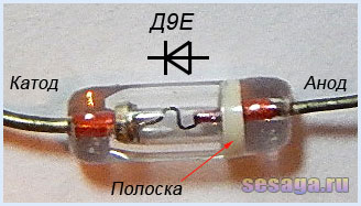
Diodes VD1 – VD4 any from the D9 series. A colored stripe is applied to the diode body on the anode side, identifying the letter of the diode.
As a rectifier assembled on diodes VD5 - VD8, a ready-made miniature diode bridge is used, designed for a voltage of 50V and a current of at least 200 mA.

If you use rectifier diodes instead of a ready-made bridge, you will have to slightly adjust the printed circuit board, or even move the diode bridge outside the main board of the set-top box and assemble it on a separate small board.
To assemble the bridge yourself, the diodes are taken with the same parameters as the factory bridge. Any rectifier diodes from the KD105, KD106, KD208, KD209, KD221, D229, KD204, KD205, 1N4001 - 1N4007 series are also suitable. If you use diodes from the KD209 or 1N4001 - 1N4007 series, then the bridge can be assembled directly from the printed circuit board directly on the contact pads of the board.
LEDs are standard with yellow, red, blue and green colors. Each channel uses 6 pieces:

Transistors VT1 and VT2 from the KT361 series with any letter index.

Transistors VT3, VT4, VT5, VT6 from the KT502 series with any letter index.

Voltage stabilizer type KREN5A with any letter index (imported analogue 7805). If you use nine-volt KREN8A or KREN8G (imported analogue 7809), then resistor R22 is not installed. Instead of a resistor, a jumper is installed on the board, which will connect the middle pin of the microcircuit to the negative bus, or this resistor is not provided at all during the manufacture of the board.

To connect the set-top box to the sound source, a three-pin jack connector is used. The cable is taken from a computer mouse.

Power transformer - ready-made or home-made with a power of at least 5 W with a voltage on the secondary winding of 12 - 15 V at a load current of 200 mA.
In addition to the article, watch the first part of the video, which shows the initial stage of assembling a color music console
This ends the first part.
If you are tempted make color music using LEDs, then select the parts and be sure to check the serviceability of diodes and transistors, for example. And we will carry out the final assembly and configuration of the color and music console.
Good luck!
Literature:
1. I. Andrianov “Attacks for radio receivers.”
2. Radio 1990 No. 8, B. Sergeev “Simple color and music consoles.”
3. Operating manual for the “Start” radio designer.