Types of capacitors. Electrical capacitors
All types of capacitors have the same basic structure; it consists of two conductive plates (plates), on which electrical charges of opposite poles are concentrated, and a layer of insulating material between them.
The materials used and the size of the plates with different parameters of the dielectric layer affect the properties of the capacitor.
Classification
Capacitors are divided into types according to the following factors.
Purpose
- General purpose . This is a popular type of capacitor used in electronics. There are no special requirements for them.
- Special . Such capacitors have increased reliability at a given voltage and other parameters when starting electric motors and special equipment.
Capacity change
- Constant capacity . They do not have the ability to change capacity.
- Variable capacity
. They can change the capacitance value when exposed to temperature, voltage, or adjustment of the position of the plates. Variable capacitors include:
Trimmer capacitors are not intended for continuous operation associated with quick capacity adjustment. They serve only for one-time setup of equipment and periodic adjustment of the capacity.
Nonlinear capacitors change their capacity under the influence of temperature and voltage according to a nonlinear graph. Capacitors whose capacitance depends on voltage are called varicondas , from temperature – thermal capacitors .
Method of protection
- Unprotected work under normal conditions, do not have any protection.
- Protected The capacitors are made in a protected housing, so they can operate in high humidity.
- Non-insulated have an open body and are not insulated from possible contact with various circuit elements.
- Isolated The capacitors are made in a closed housing.
- Compacted have a body filled with special materials.
- Sealed have a sealed housing, completely isolated from the external environment.
Type of installation
- Mounted are divided into several types;
— tape outputs;
- support screw;
— round electrodes;
— radial or axial leads. - Capacitors with screw terminals equipped with threads for connection to the circuit, used in power circuits. It is easier to fix such conclusions on cooling radiators to reduce thermal loads.
- Capacitors With snap-in terminals are a new development, they snap into place when mounted on the board. This is very convenient since there is no need to use soldering.
- Capacitors designed for surface installation, have a design feature: parts of the housing are leads.
- Capacities for printing installation made with round pins for placement on the board.
According to dielectric material
The insulation resistance between the plates depends on the parameters of the insulating material. The permissible losses and other parameters also depend on this. Let's consider the types of capacitors that have different dielectric materials.
- Capacitors with inorganic insulator from glass ceramics, glass enamel, mica. The dielectric material is coated with a metal coating or foil.
- Low frequency capacitors include insulating material in the form of weakly polar organic films, whose dielectric losses depend on the frequency of the current.
- High frequency models contain films of fluoroplastic and polystyrene.
- High Voltage Pulse Models have an insulator made of combined materials.
- In capacitors DC voltage I polytetrafluoroethylene, paper, or a combined material is used as a dielectric.
- Low voltage models operate at voltages up to 1.6 kV.
- High voltage models operate at voltages above 1.6 kV.
- Dosimetric capacitors are used to operate with low current, have low self-discharge and high insulation resistance.
- Noise suppressing capacitors reduce interference arising from the electromagnetic field and have low inductance.
- Capacities with organic insulator made using condenser paper and various films.
- Vacuum, air, gas-filled capacitors have low dielectric losses, so they are used in equipment with high frequencies.
Plate shape
- Spherical.
- Flat.
- Cylindrical.
Polarities
- Electrolytic capacitors are called oxide capacitors. When connecting them, it is mandatory to observe the polarity of the terminals. Electrolytic capacitors contain a dielectric consisting of an oxide layer formed electrochemically on an anode of tantalum or aluminum. The cathode is an electrolyte in liquid or gel form.
- Non-polar capacitors can be included in the circuit without observing polarity.
Design features
The types of capacitors discussed above are not all very popular. Therefore, let’s take a closer look at the design features of the most commonly used types of capacitors.
Air types of capacitors

Air is used as a dielectric. These types of capacitors have proven themselves when operating at high frequencies, as tuning capacitors with variable capacitance. The moving plate of the capacitor is the rotor, and the stationary plate is called the stator. When the plates are displaced relative to each other, the total area of intersection of these plates and the capacitance of the capacitor changes. Previously, such capacitors were very popular in radio receivers for tuning radio stations.
Ceramic
Such capacitors are made in the form of one or more plates made of special ceramics. Metal plates are made by sputtering a layer of metal onto a ceramic plate, then connecting it to the leads. Ceramic material can be used with different properties.

Their diversity is determined by a wide range of dielectric constants. It can reach several tens of thousands of farads per meter, and is available only for this type of container. This feature of ceramic capacitors allows you to create large capacitance values that are comparable to electrolytic capacitors, but the polarity of the connection is not important for them.
Ceramics have a nonlinear, complex dependence of properties on voltage, frequency and temperature. Due to the small size of the housing, these types of capacitors are used in compact devices.
Film
In such models, a plastic film acts as a dielectric: polycarbonate, polypropylene or polyester.

The capacitor plates are sprayed or made in the form of foil. The new material is polyphenylene sulfide.
Parameters of film capacitors
- Used for resonant circuits.
- Lowest leakage current.
- Small capacity.
- High strength.
- Withstand high current.
- Resistant to electrical breakdown (withstands high voltage).
- The highest operating temperature is up to 125 degrees.
Polymer
These models differ from electrolytic tanks in the presence of a polymer material, instead of an oxide film between the plates. They are not subject to charge leakage and swelling.

The polymer parameters provide significant pulse current, a constant temperature coefficient, and low resistance. Polymer models can replace electrolytic models in filters of pulsed sources and other devices.
Electrolytic
Electrolytic capacitors differ from paper models in the dielectric material, which is a metal oxide created by an electrochemical method on the positive plate.

The second plate is made of dry or liquid electrolyte. The electrodes are usually made of tantalum or aluminum. All electrolytic containers are considered polarized, and can only operate normally at a constant voltage at a certain polarity.
If polarity is not observed, an irreversible chemical process may occur inside the container, which will lead to its failure, or even explosion, as gas will be released.
Electrolytic ones include supercapacitors, which are called ionistors. They have a very large capacity, reaching thousands of Farads.
Tantalum electrolytic
The design of tantalum electrolytes has a peculiarity in the tantalum electrode. The dielectric consists of tantalum pentoxide.

Options
- Insignificant leakage current, unlike aluminum types.
- Small sizes.
- Immunity to external influences.
- Low active resistance.
- High sensitivity in case of wrong pole connection.
Aluminum electrolytic
The positive terminal is an aluminum electrode. Aluminum trioxide was used as a dielectric. They are used in pulse blocks and are an output filter.
Options
- Large capacity.
- Correct operation only at low frequencies.
- Increased capacitance-to-size ratio: Other types of capacitors would have larger sizes for a single capacitance.
- Large current leakage.
- Low inductance.
Paper
The dielectric between the foil plates is a special capacitor paper. In electronic devices, paper types of capacitors usually operate in high and low frequency circuits.

Metal paper capacitors have tightness, high specific capacity, high-quality electrical insulation. Their design uses vacuum metal deposition onto a paper dielectric instead of foil.
Paper capacitors do not have high mechanical strength. In this regard, its insides are placed in a metal case, which protects its device.
They are polar and non-polar. Their differences are that some are used in DC voltage circuits, while others are used in AC circuits. It is possible to use permanent capacitors in alternating voltage circuits when they are connected in series with like poles, but they do not show the best parameters.
Non-polar capacitors
Non-polar, just like resistors, can be fixed, variable or tuning.
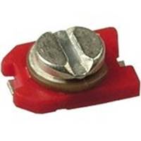
Trimmers capacitors are used to tune resonant circuits in transmitting and receiving equipment.
Rice. 1. PDA capacitors
PDA type. They consist of silver-plated plates and a ceramic insulator. They have a capacity of several tens of picofarads. It can be found in any receivers, radios and television modulators. Trimmer capacitors are also designated by the letters KT. This is followed by a number indicating the type of dielectric:
1 - vacuum; 2 - air; 3 - gas-filled; 4 - solid dielectric; 5 - liquid dielectric. For example, the designation KP2 means a variable capacitor with an air dielectric, and the designation KT4 means a tuning capacitor with a solid dielectric.
Rice. 2 Modern trimming chip capacitors
To tune radio receivers to the desired frequency, use variable capacitors(KPE)
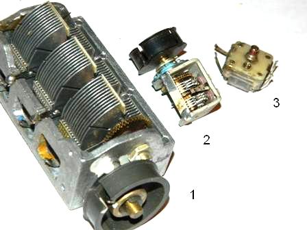
Rice. 3 Capacitors KPE
They can only be found in transmitting and receiving equipment
1- KPE with an air dielectric, can be found in any radio receiver of the 60s-80s.
2 - variable capacitor for VHF units with vernier
3 - variable capacitor, used in receiving technology of the 90s to this day, can be found in any music center, tape recorder, cassette player with a receiver. Mostly made in China.
There are a great many types of permanent capacitors; within the framework of this article it is impossible to describe all their diversity; I will only describe those that are most often found in household equipment.
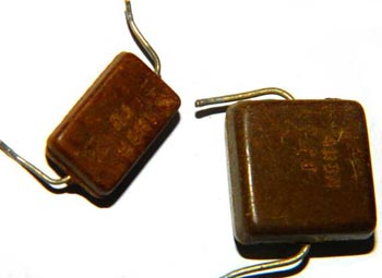
Rice. 4 Capacitor KSO
KSO capacitors - Pressed mica capacitor. Dielectric - mica, plates - aluminum coating. Filled in a brown compound housing. They are found in equipment from the 30s to the 70s, the capacity does not exceed several tens of nanofarads, and is indicated on the housing in picofarads, nanofarads and microfarads. Thanks to the use of mica as a dielectric, these capacitors are capable of operating at high frequencies because they have low losses and have a high leakage resistance of about 10^10 Ohms.

Rice. 5 Capacitors KTK
KTK capacitors - Tubular ceramic capacitor. A ceramic tube and silver plating are used as a dielectric. Widely used in oscillatory circuits of lamp equipment from the 40s to the early eighties. The color of the capacitor indicates TKE (temperature coefficient of change of capacitance). Next to the container, as a rule, the TKE group is written, which has an alphabetic or numerical designation (Table 1.) As can be seen from the table, the most heat-stable ones are blue and gray. In general, this type is very good for HF equipment.
Table 1. TKE marking of ceramic capacitors

When setting up receivers, you often have to select capacitors for the local dyne and input circuits. If the receiver uses KTK capacitors, then selecting the capacitance of the capacitors in these circuits can be simplified. To do this, several turns of PEL 0.3 wire are wound tightly onto the capacitor body next to the terminal and one of the ends of this spiral is soldered to the terminal of the capacitors. By spreading and shifting the turns of the spiral, you can adjust the capacitance of the capacitor within small limits. It may happen that by connecting the end of the spiral to one of the terminals of the capacitor, it is not possible to achieve a change in capacitance. In this case, the spiral should be soldered to another terminal.
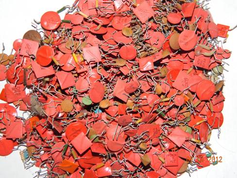

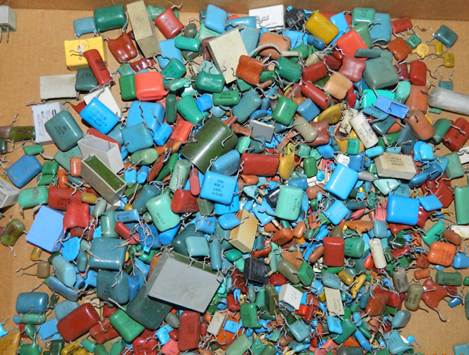
Rice. 6 Ceramic capacitors. Soviet ones at the top, imported ones at the bottom.
Ceramic capacitors are usually called “red flag” capacitors, sometimes called “clay” capacitors. These capacitors are widely used in high frequency circuits. Typically, these capacitors are not quoted and are rarely used by hobbyists, since capacitors of the same type can be made of different ceramics and have different characteristics. Ceramic capacitors gain in size but lose in thermal stability and linearity. Capacity and TKE are indicated on the body (Table 2.)
Table 2
Just look at the permissible change in capacitance for capacitors with TKE N90, the capacitance can change almost twice! For many purposes this is not acceptable, but still you should not reject this type; with a small temperature difference and not strict requirements, they can be used. By using parallel connection of capacitors with different signs of TKE, it is possible to obtain a fairly high stability of the resulting capacitance. You can find them in any equipment; the Chinese are especially fond of them in their crafts.
They have a capacity designation on the body in picofarads or nanofarads; imported ones are marked with a numerical code. The first two digits indicate the capacitance value in picofarads (pF), the last two digits indicate the number of zeros. When the capacitor has a capacitance of less than 10 pF, the last digit may be "9". For capacitances less than 1.0 pF, the first digit is “0”. The letter R is used as a decimal point. For example, code 010 is 1.0 pF, code 0R5 is 0.5 pF. Several examples are collected in the table:
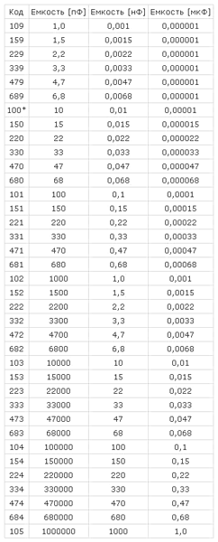
Alphanumeric marking:
22p-22 picofarads
2n2- 2.2 nanofarads
n10 - 100 picofarads
I would like to especially note ceramic capacitors of the KM type, they are used in industrial equipment and military devices, they have high stability, they are very difficult to find because they contain rare earth metals, and if you find a board where this type of capacitor is used, then in 70% of cases they were cut out before you).

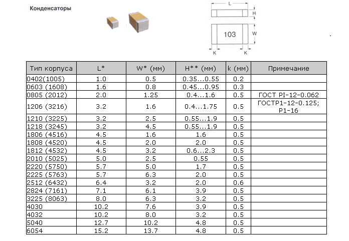
In the last decade, radio components for surface mounting have very often begun to be used; here are the main standard sizes of housings for ceramic chip capacitors
MBM capacitors are a metal-paper capacitor (Fig. 6), usually used in tube sound amplification equipment. Now highly prized by some audiophiles. This type also includes military-grade K42U-2 capacitors, but they can sometimes be found in household equipment.
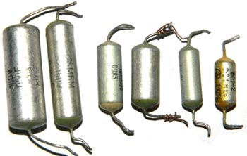

Rice. 7 Capacitor MBM and K42U-2
It should be noted separately that such types of capacitors as MBGO and MBGCh (Fig. 8), are often used by amateurs as starting capacitors to start electric motors. As an example, my engine reserve is 7 kW (Fig. 9.). Designed for high voltage from 160 to 1000V, which gives them many different applications in everyday life and industry. It should be remembered that for use in a home network, you need to take capacitors with an operating voltage of at least 350V. You can find such capacitors in old household washing machines, various devices with electric motors and in industrial installations. They are often used as filters for acoustic systems, having good parameters for this.
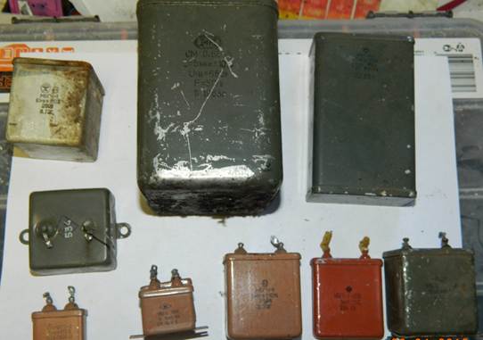
Rice. 8. MBGO, MBGCH

Rice. 9
In addition to the designation indicating design features (KSO - compressed mica capacitor, KTK - ceramic tubular capacitor, etc.), there is a designation system for constant-capacity capacitors, consisting of a number of elements: in the first place is the letter K, in the second place is a two-digit number, the first digit of which characterizes the type of dielectric, and the second - the features of the dielectric or operation, then the serial number of the development is put through a hyphen.
For example, the designation K73-17 means a polyethylene-terephthalate film capacitor with a development serial number of 17.

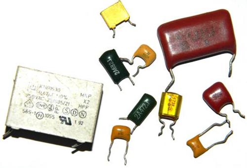
Rice. 10. Different types of capacitors

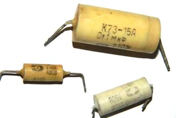
Rice. 11. Capacitor type K73-15
Main types of capacitors, imported analogues in parentheses.
K10 - Ceramic, low voltage (Upa6<1600B)
K50 - Electrolytic, foil, Aluminum
K15 - Ceramic, high voltage (Upa6>1600V)
K51 - Electrolytic, foil, tantalum, niobium, etc.
K20 - Quartz
K52 - Electrolytic, volumetric porous
K21 -Glass
K53 - Oxide semiconductor
K22 - Glass-ceramic
K54 - Oxide-metallic
K23 - Glass enamel
K60- With air dielectric
K31-Mica low power (Mica)
K61 - Vacuum
K32 - Mica high power
K71 - Film polystyrene (KS or FKS)
K40 - Paper low-voltage (Irab<2 kB) с фольговыми обкладками
K72 -Film fluoroplastic (TFT)
K73 - Film polyethylene terephthalate (KT, TFM, TFF or FKT)
K41 - Paper high-voltage (irab>2 kB) with foil coverings
K75 -Film combined
K76 – Lacquer film (MKL)
K42 - Paper with metallized covers (MP)
K77 - Film, Polycarbonate (KC, MKC or FKC)
K78 – Film polypropylene (KP, MKP or FKP)
Capacitors with a film dielectric are popularly called mica; the various dielectrics used give good TKE indicators. As plates in film capacitors, either aluminum foil or thin layers of aluminum or zinc sprayed onto a dielectric film are used. They have fairly stable parameters and are used for any purpose (not for all types). They are found everywhere in household equipment. The housing of such capacitors can be either metal or plastic and have a cylindrical or rectangular shape (Fig. 10.) Imported mica capacitors (Fig. 12)
Rice. 12. Imported mica capacitors
On capacitors, the nominal deviation from capacitance is indicated; it can be shown as a percentage or have a letter code. Basically, in household equipment, capacitors with tolerances H, M, J, K are widely used. The letter indicating the tolerance is indicated after the value of the nominal capacitance of the capacitor, like this: 22nK, 220nM, 470nJ.
Table for deciphering the conditional letter code of the permissible deviation of capacitor capacitance. Tolerance in %
|
Letter designation |
||
The value of the permissible operating voltage of the capacitor is important; it is indicated after the rated capacity and tolerance. It is designated in volts with the letter B (old marking) and V (new marking). For example, like this: 250V, 400V, 1600V, 200V. In some cases, the V is omitted.
Sometimes Latin letter coding is used. To decipher, you should use the letter coding table for the operating voltage of capacitors.
|
Rated voltage, V |
Designation letter |
Fans of Nikola Tesla have a frequent need for high-voltage capacitors, here are some that can be found, mainly in televisions in horizontal scanning units.
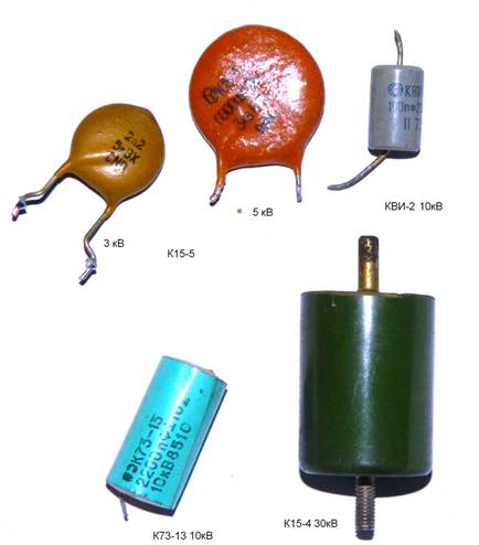
Rice. 13. High voltage capacitors
Polar capacitors
Polar capacitors include all electrolytic ones, which are:
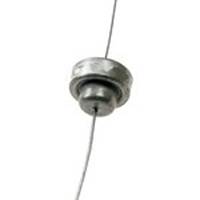
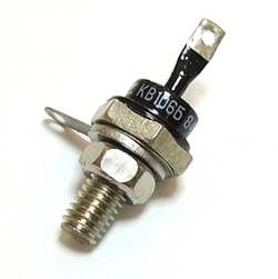
Aluminum electrolytic capacitors have high capacity, low cost and availability. Such capacitors are widely used in radio instrument making, but have a significant drawback. Over time, the electrolyte inside the capacitor dries out and they lose capacity. Along with the capacitance, the equivalent series resistance increases and such capacitors no longer cope with the assigned tasks. This usually causes malfunctions in many household appliances. Using used capacitors is not advisable, but still, if you want to use them, you need to carefully measure the capacitance and esr, so that you don’t have to look for the reason for the device’s inoperability. I don’t see any point in listing the types of aluminum capacitors, since there are no special differences in them, except for geometric parameters. Capacitors can be radial (with leads from one end of the cylinder) and axial (with leads from opposite ends), there are capacitors with one lead, the second one is a housing with a threaded tip (it is also a fastener), such capacitors can be found in old tube radio and television equipment. It is also worth noting that on computer motherboards and in switching power supplies there are often capacitors with low equivalent resistance, the so-called LOW ESR, so they have improved parameters and are replaced only with similar ones, otherwise there will be an explosion when first turned on.


Rice. 14. Electrolytic capacitors. Bottom - for surface mounting.
Tantalum capacitors are better than aluminum capacitors due to the use of more expensive technology. They use a dry electrolyte, so they are not prone to “drying out” of aluminum capacitors. In addition, tantalum capacitors have lower active resistance at high frequencies (100 kHz), which is important when used in switching power supplies. The disadvantage of tantalum capacitors is the relatively large decrease in capacitance with increasing frequency and increased sensitivity to polarity reversal and overloads. Unfortunately, this type of capacitor is characterized by low capacitance values (usually no more than 100 µF). High sensitivity to voltage forces developers to increase the voltage margin by two or more times.

Rice. 14. Tantalum capacitors. The first three are domestic, the penultimate one is imported, the last one is imported for surface mounting.
Main dimensions of tantalum chip capacitors: 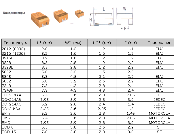
One of the types of capacitors (in fact, these are semiconductors and have little in common with ordinary capacitors, but it still makes sense to mention them) include varicaps. This is a special type of diode capacitor that changes its capacitance depending on the applied voltage. They are used as elements with electrically controlled capacitance in circuits for tuning the frequency of an oscillatory circuit, dividing and multiplying frequencies, frequency modulation, controlled phase shifters, etc.
Rice. 15 Varicaps kv106b, kv102
Also very interesting are “supercapacitors” or ionistors. Although small in size, they have enormous capacity and are often used to power memory chips, and sometimes they replace electrochemical batteries. Ionistors can also work in a buffer with batteries in order to protect them from sudden surges in load current: at low load current, the battery recharges the supercapacitor, and if the current increases sharply, the ionistor will release the stored energy, thereby reducing the load on the battery. With this use case, it is placed either directly next to the battery or inside its housing. They can be found in laptops as a battery for CMOS.
The disadvantages include:
Energy density is lower than that of batteries (5-12 Wh/kg at 200 Wh/kg for lithium-ion batteries).
The voltage depends on the state of charge.
Possibility of internal contacts burning out during a short circuit.
High internal resistance compared to traditional capacitors (10...100 Ohms for a 1 F × 5.5 V ionistor).
Significantly greater self-discharge compared to batteries: about 1 µA for a 2 F × 2.5 V ionistor.


Rice. 16. Ionistors
- Translation
If you regularly create electrical circuits, you've probably used capacitors. It's a standard circuit component, just like resistor, that you just grab off the shelf without a second thought. We use capacitors to smooth out voltage/current ripple, to match loads, as a power source for low-power devices, and other applications.
But a capacitor is not just a bubble with two wires and a couple of parameters - operating voltage and capacitance. There is a huge array of technologies and materials with different properties used to create capacitors. And although in most cases almost any capacitor of suitable capacity will do for any task, a good understanding of how these devices work can help you choose not just the right one, but the best fit one. If you have ever had a problem with temperature stability or the task of finding the source of additional noise, you will appreciate the information in this article. 
Let's start simple
It's best to start simple and describe the basic principles of how capacitors work before moving on to the real devices. An ideal capacitor consists of two conducting plates separated by a dielectric. The charge collects on the plates, but cannot flow between them - the dielectric has insulating properties. This is how the capacitor accumulates charge.Capacitance is measured in farads: a capacitor of one farad produces a voltage of one volt if it contains a charge of one coulomb. Like many other SI units, it's an impractical size, so unless you count supercapacitors, which we won't talk about here, you'll likely end up with micro-, nano-, and picofarads. The capacitance of any capacitor can be derived from its dimensions and dielectric properties - if interested, the formula for this can be found on Wikipedia. You don't need to memorize it unless you're studying for an exam, but it does contain one useful fact. The capacitance is proportional to the dielectric constant εr of the dielectric used, which has resulted in a variety of capacitors being commercially available using different dielectric materials to achieve larger capacitances or improve voltage characteristics.
Aluminum electrolytic

Aluminum electrolytic capacitors use an anodic oxidation layer on an aluminum sheet as one dielectric plate, and the electrolyte from an electrochemical cell as the other plate. The presence of an electrochemical cell makes them polar, that is, the DC voltage must be applied in one direction, and the anodized plate must be the anode, or positive.
In practice, their plates are made in the form of a sandwich of aluminum foil, wrapped in a cylinder and located in an aluminum can. The operating voltage depends on the depth of the anodized layer.
Electrolytic capacitors have the largest capacitance among common ones, from 0.1 to thousands of microfarads. Due to the close packing of the electrochemical cell, they have a large equivalent series inductance (ESI, or effective inductance), which is why they cannot be used at high frequencies. They are typically used for power smoothing and decoupling as well as coupling at audio frequencies.
Tantalum electrolytic

Surface Mounted Tantalum Capacitor
Tantalum electrolytic capacitors are manufactured as a sintered tantalum anode with a large surface area on which a thick layer of oxide is grown and then a manganese dioxide electrolyte is placed as the cathode. The combination of the large surface area and dielectric properties of tantalum oxide results in high capacitance per volume. As a result, such capacitors are much smaller than aluminum capacitors of comparable capacity. Like the latter, tantalum capacitors have polarity, so direct current must flow in exactly one direction.
Their available capacitance varies from 0.1 to several hundred microfarads. They have much lower leakage resistance and equivalent series resistance (ESR), making them used in testing, instrumentation, and high-end audio applications where these properties are useful.
In the case of tantalum capacitors, it is necessary to especially monitor the failure status; it happens that they catch fire. Amorphous tantalum oxide is a good dielectric, and in crystalline form it becomes a good conductor. Improper use of a tantalum capacitor - for example, applying too much inrush current - can cause the dielectric to change form, which will increase the current passing through it. It is true that earlier generations of tantalum capacitors had a reputation for fire problems, and improved manufacturing methods have led to more reliable products.
Polymer films
An entire family of capacitors uses polymer films as dielectrics, and the film is either sandwiched between twisted or interleaved layers of metal foil or has a metallized layer on the surface. Their operating voltage can reach up to 1000 V, but they do not have high capacitances - this is usually from 100 pF to a few microfarads. Each type of film has its pros and cons, but in general the entire family has lower capacitance and inductance than electrolytic ones. Therefore, they are used in high-frequency devices and for decoupling in electrically noisy systems, as well as in general purpose systems.Polypropylene capacitors are used in circuits that require good thermal and frequency stability. They are also used in power systems, to suppress EMI, in systems using high voltage alternating currents.
Polyester capacitors, although they do not have the same temperature and frequency characteristics, are cheap and can withstand high temperatures when soldered for surface mounting. Because of this, they are used in circuits intended for use in non-critical applications.
Polyethylene naphthalate capacitors. They do not have stable temperature and frequency characteristics, but can withstand much higher temperatures and stresses compared to polyester ones.
Polyethylene sulfide capacitors have the temperature and frequency characteristics of polypropylene, and in addition can withstand high temperatures.
In old equipment you can come across polycarbonate and polystyrene capacitors, but now they are no longer used.
Ceramics

The history of ceramic capacitors is quite long - they have been used from the first decades of the last century to the present day. Early capacitors were a single layer of ceramic, metallized on both sides. Later ones are also multilayer, where plates with metallization and ceramics are interspersed. Depending on the dielectric, their capacitances vary from 1 pF to tens of microfarads, and voltages reach kilovolts. In all electronics industries where low capacitance is required, both single-layer ceramic disks and multi-layer surface-mount stack capacitors can be found.
The easiest way to classify ceramic capacitors is by dielectrics, since they are what give the capacitor all its properties. Dielectrics are classified according to three-letter codes, which encrypt their operating temperature and stability.
C0G has better stability in capacitance with respect to temperature, frequency and voltage. Used in high-frequency circuits and other high-speed circuits.
X7R do not have such good temperature and voltage characteristics, therefore they are used in less critical cases. This usually includes decoupling and various universal applications.
Y5V have much higher capacity, but their temperature and voltage characteristics are even lower. Also used for decoupling and in various general purpose applications.
Since ceramics often also have piezoelectric properties, some ceramic capacitors also exhibit a microphonic effect. If you have worked with high voltages and frequencies in the audio range, such as with tube amplifiers or electrostatics, you may have heard the capacitors “singing.” If you used a piezoelectric capacitor to provide frequency stabilization, you might find that its sound is modulated by the vibration of its surroundings.
As we already mentioned, this article does not aim to cover all capacitor technologies. Taking a look at the electronics catalog you will find that some of the technologies available are not covered here. Some offers from catalogs are already outdated, or have such a narrow niche that you most often will not come across them. Our hope was to demystify some of the popular capacitor models and help you choose the right components when designing your own devices. If we've whetted your appetite, you may want to check out our article on inductors.
Please write about any inaccuracies or errors you find via
Capacitor
The basis of the capacitor design is two conductive plates, between which there is a dielectric

On the left are surface mount capacitors; on the right - capacitors for volumetric installation; on top - ceramic; below - electrolytic.

Various capacitors for volumetric mounting
Capacitor Properties
A capacitor in a DC circuit can conduct current at the moment it is connected to the circuit (charging or recharging of the capacitor occurs); at the end of the transient process, no current flows through the capacitor, since its plates are separated by a dielectric. In an alternating current circuit, it conducts alternating current oscillations through cyclic recharging of the capacitor.
where is the imaginary unit, is the frequency of the flowing sinusoidal current, and is the capacitance of the capacitor. It also follows that the reactance of the capacitor is equal to: ![]() . For direct current, the frequency is zero, therefore the reactance of the capacitor is infinite (ideally).
. For direct current, the frequency is zero, therefore the reactance of the capacitor is infinite (ideally).
On electrical circuit diagrams, the nominal capacitance of capacitors is usually indicated in microfarads (1 µF = 10 6 pF) and picofarads, but often in nanofarads. With a capacity of no more than 0.01 µF, the capacitance of the capacitor is indicated in picofarads, but it is permissible not to indicate the unit of measurement, i.e. the postfix “pF” is omitted. When indicating the nominal value of a capacity in other units, indicate the unit of measurement (picoFarad). For, as well as for high-voltage capacitors in the diagrams, after the designation of the capacitance rating, their maximum operating voltage is indicated in volts (V) or kilovolts (kV). For example: “10 microns x 10 V”. For indicate the range of change in capacity, for example: “10 – 180”. Currently, capacitors are manufactured with nominal capacities from the decimal logarithmic series of values E3, E6, E12, E24, i.e. there are 3, 6, 12, 24 values per decade, so that the values with the appropriate tolerance (scatter) cover the entire decade.
Characteristics of capacitors
Basic parameters
Capacity
The main characteristic of a capacitor is its capacity. The designation of a capacitor indicates the value of the nominal capacitance, while the actual capacitance can vary significantly depending on many factors. The actual capacitance of a capacitor determines its electrical properties. Thus, according to the definition of capacitance, the charge on the plate is proportional to the voltage between the plates ( q = CU ). Typical capacitance values range from units of picofarads to hundreds of microfarads. However, there are capacitors with a capacity of up to tens of farads.
The capacitance of a flat capacitor, consisting of two parallel metal plates with an area each, located at a distance from each other, in the SI system is expressed by the formula: , where is the relative dielectric constant of the medium filling the space between the plates (this formula is valid only when much less than the linear dimensions of the plates ).
To obtain large capacities, capacitors are connected in parallel. In this case, the voltage between the plates of all capacitors is the same. Total battery capacity parallel of connected capacitors is equal to the sum of the capacitances of all capacitors included in the battery.
![]()
If all parallel-connected capacitors have the same distance between the plates and the same dielectric properties, then these capacitors can be represented as one large capacitor, divided into fragments of a smaller area.
When capacitors are connected in series, the charges on all capacitors are equal. Total battery capacity sequentially connected capacitors is equal to
![]()
![]() or
or ![]()
This capacity is always less than the minimum capacity of the capacitor included in the battery. However, with a series connection, the possibility of breakdown of capacitors is reduced, since each capacitor accounts for only part of the potential difference of the voltage source.
If the area of the plates of all capacitors connected in series is the same, then these capacitors can be represented as one large capacitor, between the plates of which there is a stack of dielectric plates of all the capacitors that make it up.
Specific capacity
Capacitors are also characterized by specific capacitance - the ratio of capacitance to the volume (or mass) of the dielectric. The maximum value of specific capacitance is achieved with a minimum thickness of the dielectric, but at the same time its breakdown voltage decreases.
Rated voltage
Another, no less important characteristic of capacitors is the rated voltage - the voltage value indicated on the capacitor at which it can operate under specified conditions during its service life while maintaining parameters within acceptable limits.
The rated voltage depends on the design of the capacitor and the properties of the materials used. During operation, the voltage on the capacitor should not exceed the rated voltage. For many types of capacitors, the permissible voltage decreases as temperature increases.
Polarity

Capacitors that collapsed without explosion due to temperature and voltage not suitable for operating conditions.
Many oxide dielectric (electrolytic) capacitors operate only when the voltage polarity is correct due to the chemical characteristics of the interaction of the electrolyte with the dielectric. When the voltage polarity is reversed, electrolytic capacitors usually fail due to chemical destruction of the dielectric with a subsequent increase in current, boiling of the electrolyte inside and, as a result, the possibility of explosion of the housing.
Explosions of electrolytic capacitors are a fairly common occurrence. The main cause of explosions is overheating of the capacitor, caused in most cases by leakage or an increase in equivalent series resistance due to aging (relevant for pulsed devices). To reduce damage to other parts and personnel injuries, in modern large-capacity capacitors a valve is installed or a notch is made on the body (you can often notice it in the shape of the letter X, K or T at the end). When the internal pressure increases, the valve opens or the housing is destroyed along the notch, the evaporated electrolyte comes out in the form of a corrosive gas, and the pressure drops without explosion or fragments.
Real capacitors, in addition to capacitance, also have their own resistance and inductance. With a high degree of accuracy, the equivalent circuit of a real capacitor can be represented as follows:
|
|

Electrical insulation resistance of the capacitor - r
Insulation resistance is the capacitor's resistance to direct current, given by r = U / I ut, Where U- voltage applied to the capacitor, I ut- leakage current.
Equivalent series resistance - R
Equivalent series resistance (ESR, English. ESR) is caused mainly by the electrical resistance of the material of the plates and leads of the capacitor and the contact(s) between them, as well as losses in the dielectric. Typically, the ESR increases with increasing frequency of the current flowing through the capacitor.
In most cases, this parameter can be neglected, but sometimes (for example, in the case of using electrolytic capacitors in switching power supply filters) a sufficiently small value can be vital for the reliability of the device (see, for example, Capacitor plague) .
Equivalent series inductance - L
The equivalent series inductance is mainly due to the intrinsic inductance of the plates and leads of the capacitor. At low frequencies (up to a few kilohertz) it is usually not taken into account due to its insignificance.
Loss tangent
Loss tangent is the ratio of the imaginary and real parts of the complex dielectric constant. ![]()
Temperature coefficient of capacity (TKE)
TKE - relative change in capacitance when the ambient temperature changes by one degree Celsius (Kelvin). Thus, the value of capacitance versus temperature is represented by the linear formula:
,where Δ T- temperature increase in °C or °K relative to the normal conditions under which the capacitance value is specified. TKE is used to characterize capacitors with a significant linear dependence of capacitance on temperature. However, TKE is not determined for all types of capacitors. Capacitors that have a nonlinear dependence of capacitance on temperature, and capacitors with large changes in capacitance from the influence of ambient temperature, have an indication in the designation of the relative change in capacitance in the operating temperature range.
Dielectric absorption
If a charged capacitor is quickly discharged to zero voltage by connecting a low-resistance load, and then remove the load and observe the voltage at the capacitor terminals, we will see that the voltage slowly rises. This phenomenon is called dielectric absorption or electric charge adsorption. The capacitor behaves as if many series connections were connected in parallel to it. R.C.-chains with different time constants. The intensity of this effect depends mainly on the properties of the dielectric of the capacitor. A similar effect can be observed on most electrolytic capacitors, but in them it is a consequence

In radio electronics, a huge number of various capacitors are used. They all differ in such basic parameters as nominal capacity, operating voltage and tolerance.
But these are just the basic parameters. Another important parameter can be what kind of dielectric the capacitor is made of. Let us consider in more detail what types of dielectric capacitors there are.
Used in radio electronics polar And non-polar capacitors. The difference between polar capacitors and non-polar ones is that polar ones are included in the electronic circuit in strict accordance with the indicated polarity. Polar capacitors include so-called electrolytic capacitors. The most common are radial aluminum electrolytic capacitors. In domestic markings they are designated K50-35.
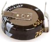
Axial capacitors have wire leads placed on the sides of the cylindrical body, in contrast to radial capacitors, the leads of which are placed on one side of the cylindrical body. Axial electrolytes are capacitors marked K50-29 K50-12, K50-15 and K50-24.

Axial electrolytic capacitors of the K50-29 series and imported from PHILIPS
In everyday life, radio amateurs call electrolytic capacitors “electrolytes”.
They can be found in power supplies of electronic equipment. They mainly serve to filter and smooth the rectified voltage. Electrolytic capacitors are also actively used in audio amplifiers (amplifiers) to separate the direct and alternating current components.
Electrolytic capacitors have a fairly significant capacity. In general, rated capacity values range from 0,1 microfarads (0.1 µF) up to 100.000 microfarad (100,000 µF).
The rated operating voltage of electrolytic capacitors can range from 10 volts to several hundred volts (100 – 500 volts). Of course, it is possible that there are other samples with a different capacity and operating voltage, but in practice they are quite rare.
It is worth noting that the nominal capacity of electrolytic capacitors decreases as their service life increases.
Therefore, to assemble homemade electronic devices, it is worth using either new purchased ones or those capacitors that have been used in electrical equipment for a short period of time. Otherwise, you may encounter a situation where your home-made device does not work due to a malfunction of the electrolytic capacitor. The most common defect of “old” electrolytes is loss of capacity and increased leakage.
Before reuse, you should carefully check the capacitor, which was previously in use.
Experienced radio mechanics can tell you a lot about the quality of electrolytic capacitors. At the time of the widespread use of Soviet color televisions, there was a very common malfunction of televisions due to low-quality electrolytes. Sometimes it got to the point that the TV technician replaced almost all the electrolytic capacitors in the TV circuit, after which the device worked properly for many years.
Recently, compact electrolytic capacitors for surface mounting have become increasingly widespread. Their dimensions are significantly smaller than classic output ones.

Electrolytic aluminum capacitors for SMD mounting on a CD drive board
Miniature tantalum capacitors also exist. They are quite small in size and designed for SMD mounting. They can be easily found on printed circuit boards of miniature MP3 players, mobile phones, and motherboards of laptops and computers.

Tantalum electrolytic capacitors on the printed circuit board of an MP-3 player
Despite their small size, tantalum capacitors have a significant capacity. They are similar to surface mount aluminum electrolytic capacitors, but are significantly smaller in size.

Tantalum SMD capacitor with a capacity of 47 uF and an operating voltage of 6 volts.
Computer CD drive circuit board
Mostly in compact equipment there are tantalum capacitors of 6.3 μF, 10 μF, 22 μF, 47 μF, 100 μF, 470 μF and for an operating voltage of 10 -16 volts. Such a low operating voltage is due to the fact that the power supply voltage in small-sized electronics rarely exceeds a threshold of 5 - 10 volts. Of course, there are also higher voltage examples.
In addition to tantalum capacitors, polymer surface-mount capacitors are also used in miniature electronics. Such capacitors are made using solid polymer. It acts as a negative plate - cathode . Positive output - anode - aluminum foil serves as a polymer capacitor. Such capacitors suppress electrical noise and ripple well and have high temperature stability.
Tantalum capacitors indicate polarity, which must be taken into account when using them in homemade designs.
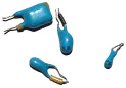
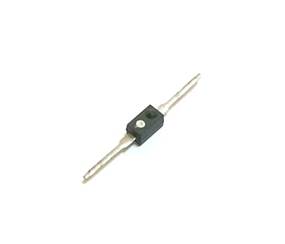
In addition to tantalum capacitors, SMD packages also have lead capacitors with a tantalum dielectric. Their shape resembles a drop. The negative terminal is marked with a stripe on the housing.
Such capacitors also have all the advantages of surface-mount tantalum capacitors, namely low leakage current, high temperature and frequency stability, and longer service life compared to conventional capacitors. They are actively used in telecommunications equipment and computer technology.

Output tantalum capacitor with a capacity of 10 microfarads and an operating voltage of 16 volts
Among electrolytic capacitors there are also non-polar . They look just like regular electrolytic capacitors, but the polarity of the applied voltage is not important to them. They are used in circuits with alternating or pulsating current, where the use of polarized capacitors is not possible. Non-polar capacitors are labeled K50-6. You can distinguish a polar capacitor from a non-polar one, for example, by the absence of polarity markings on its body.