PCI bus versions. PCI interface in a computer: types and purpose. Photo PCI bus frequency in BIOS
In the spring of 1991, Intel completed development of the first prototype version of the PCI bus. The engineers were tasked with developing an inexpensive and high-performance solution that would realize the capabilities of the 486, Pentium and Pentium Pro processors. In addition, it was necessary to take into account the mistakes made by VESA when designing the VLB bus (the electrical load did not allow connecting more than 3 expansion cards), as well as to implement automatic device configuration.
In 1992, the first version of the PCI bus appeared, Intel announced that the bus standard would be open, and created the PCI Special Interest Group. Thanks to this, any interested developer has the opportunity to create devices for the PCI bus without the need to purchase a license. The first version of the bus had a clock frequency of 33 MHz, could be 32- or 64-bit, and devices could operate with signals of 5 V or 3.3 V. Theoretically, the bus throughput was 133 MB / s, but in reality the throughput was about 80 MB/s
Key Features:
- bus frequency - 33.33 or 66.66 MHz, synchronous transmission;
- bus width - 32 or 64 bits, multiplexed bus (address and data are transmitted over the same lines);
- peak throughput for the 32-bit version operating at 33.33 MHz is 133 MB/s;
- memory address space - 32 bits (4 bytes);
- address space of I/O ports - 32 bits (4 bytes);
- configuration address space (for one function) - 256 bytes;
- voltage - 3.3 or 5 V.
Photos of connectors:
| MiniPCI - 124 pin | |
| MiniPCI Express MiniSata/mSATA - 52 pin | |
| Apple MBA SSD, 2012 | |
| Apple SSD, 2012 | |
| Apple PCIe SSD | |
| MXM, Graphics Card, 230 / 232 pin | |
|
MXM2 NGIFF 75 pins KEY A PCIe x2 KEY B PCIe x4 Sata SMBus |
|
| MXM3, Graphics Card, 314 pin | |
| PCI 5V |  |
| PCI Universal | |
| PCI-X 5v | |
| AGP Universal | |
| AGP 3.3v | |
| AGP 3.3 v + ADS Power | |
| PCIe x1 | |
| PCIe x16 | |
| Custom PCIe | |
| ISA 8bit |  |
| ISA 16bit | |
| eISA | |
| VESA | |
| NuBus | |
| PDS | |
| PDS | |
| Apple II/GS Expasion slot |  |
| PC/XT/AT expasion bus 8 bit | |
| ISA (industry standard architecture) - 16 bit | |
| eISA | |
| MBA - Micro Bus architecture 16 bit | |
| MBA - Micro Bus architecture with 16 bit video | |
| MBA - Micro Bus architecture 32 bit | |
| MBA - Micro Bus architecture with 32 bit video | |
| ISA 16 + VLB (VESA) | |
| Processor Direct Slot PDS | |
| 601 Processor Direct Slot PDS | |
| LC Processor Direct Slot PERCH | |
| NuBus | |
| PCI (Peripheral Computer Interconnect) - 5v |  |
| PCI 3.3v | |
| CNR (Communications / network riser) | |
| AMR (Audio/Modem Riser) | |
| ACR (Advanced communication riser) | |
| PCI-X (Peripheral PCI) 3.3v | |
| PCI-X 5v | |
| PCI 5v + RAID option - ARO | |
| AGP 3.3v | 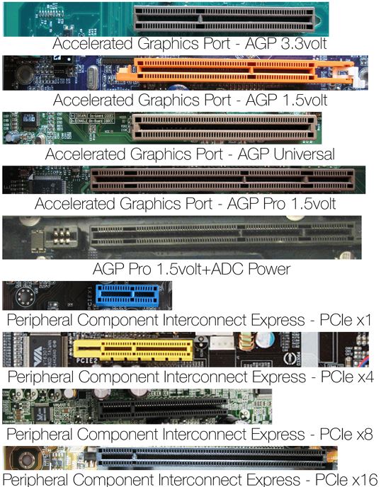 |
| AGP 1.5v | |
| AGP Universal | |
| AGP Pro 1.5v | |
| AGP Pro 1.5v+ADC power | |
| PCIe (peripheral component interconnect express) x1 | |
| PCIe x4 | |
| PCIe x8 | |
| PCIe x16 |
PCI 2.0
The first version of the basic standard to become widespread used both cards and slots with a signal voltage of only 5 volts. Peak throughput - 133 MB/s.
PCI 2.1 - 3.0
They differed from version 2.0 in the possibility of simultaneous operation of several bus masters (English bus-master, so-called competitive mode), as well as the appearance of universal expansion cards capable of operating both in slots using a voltage of 5 volts, and in slots using 3 .3 volts (with a frequency of 33 and 66 MHz, respectively). Peak throughput for 33 MHz is 133 MB/s, and for 66 MHz it is 266 MB/s.
- Version 2.1 - work with cards designed for a voltage of 3.3 volts, and the presence of appropriate power lines were optional.
- Version 2.2 - expansion cards made in accordance with these standards have a universal power connector key and are able to work in many later types of PCI bus slots, as well as, in some cases, in version 2.1 slots.
- Version 2.3 - Incompatible with PCI cards designed to use 5 volts, despite the continued use of 32-bit slots with a 5 volt key. Expansion cards have a universal connector, but are not able to work in 5-volt slots of earlier versions (up to 2.1 inclusive).
- Version 3.0 - completes the transition to 3.3 volt PCI cards, 5 volt PCI cards are no longer supported.
PCI 64
An extension of the basic PCI standard, introduced in version 2.1, that doubles the number of data lanes, and therefore the throughput. The PCI 64 slot is an extended version of the regular PCI slot. Formally, the compatibility of 32-bit cards with 64-bit slots (provided there is a common supported signal voltage) is full, but the compatibility of a 64-bit card with 32-bit slots is limited (in any case there will be a loss of performance). Operates at a clock frequency of 33 MHz. Peak throughput - 266 MB/s.
- Version 1 - uses a 64-bit PCI slot and a voltage of 5 volts.
- Version 2 - uses a 64-bit PCI slot and a voltage of 3.3 volts.
PCI 66
PCI 66 is a 66 MHz evolution of PCI 64; uses 3.3 volts in the slot; the cards have a universal or 3.3 V form factor. Peak throughput is 533 MB/s.
PCI 64/66
The combination of PCI 64 and PCI 66 allows for four times the data transfer speed of the basic PCI standard; uses 64-bit 3.3V slots, compatible only with universal ones, and 3.3V 32-bit expansion cards. PCI64/66 cards have either a universal (but with limited compatibility with 32-bit slots) or a 3.3-volt form factor (the latter option is fundamentally incompatible with 32-bit 33-MHz slots of popular standards). Peak throughput - 533 MB/s.
PCI-X
PCI-X 1.0 is an expansion of the PCI64 bus with the addition of two new operating frequencies, 100 and 133 MHz, as well as a separate transaction mechanism to improve performance when multiple devices operate simultaneously. Generally backward compatible with all 3.3V and generic PCI cards. PCI-X cards are usually implemented in a 64-bit 3.3B format and have limited backward compatibility with PCI64/66 slots, and some PCI-X cards are in a universal format and are capable of working (although this has almost no practical value) in a regular PCI 2.2/2.3. In difficult cases, in order to be completely confident in the functionality of the combination of the motherboard and expansion card, you need to look at the compatibility lists of the manufacturers of both devices.
PCI-X 2.0
PCI-X 2.0 - further expansion of the capabilities of PCI-X 1.0; frequencies of 266 and 533 MHz have been added, as well as parity error correction during data transmission (ECC). Allows splitting into 4 independent 16-bit buses, which is used exclusively in embedded and industrial systems; The signal voltage has been reduced to 1.5 V, but the connectors are backward compatible with all cards using a signal voltage of 3.3 V. Currently, for the non-professional segment of the high-performance computer market (powerful workstations and entry-level servers), in which it is used PCI-X bus; very few motherboards supporting the bus are produced. An example of a motherboard for this segment is ASUS P5K WS. In the professional segment it is used in RAID controllers and SSD drives for PCI-E.
Mini PCI
Form factor PCI 2.2, intended for use mainly in laptops.
PCI Express
PCI Express, or PCIe, or PCI-E (also known as 3GIO for 3rd Generation I/O; not to be confused with PCI-X and PXI) - computer bus(although at the physical level it is not a bus, being a point-to-point connection), using software model PCI buses and a high-performance physical protocol based on serial data transmission. The development of the PCI Express standard was started by Intel after abandoning the InfiniBand bus. Officially, the first basic PCI Express specification appeared in July 2002. The development of the PCI Express standard is carried out by the PCI Special Interest Group.
Unlike the PCI standard, which used a common bus for data transfer with multiple devices connected in parallel, PCI Express, in general, is a packet network with star topology. PCI Express devices communicate with each other through a medium formed by switches, with each device directly connected by a point-to-point connection to the switch. In addition, the PCI Express bus supports:
- hot swap cards;
- guaranteed bandwidth (QoS);
- energy management;
- monitoring the integrity of transmitted data.
The PCI Express bus is intended to be used only as a local bus. Since the PCI Express software model is largely inherited from PCI, existing systems and controllers can be modified to use the PCI Express bus by replacing only the physical layer, without modifying the software. The high peak performance of the PCI Express bus allows it to be used instead of AGP buses, and even more so PCI and PCI-X. De facto, PCI Express replaced these buses in personal computers.
- MiniCard (Mini PCIe) - replacement for the Mini PCI form factor. The Mini Card connector has the following buses: x1 PCIe, 2.0 and SMBus.
- M.2 is the second version of Mini PCIe, up to x4 PCIe and SATA.
- ExpressCard - similar to PCMCIA form factor. The ExpressCard connector supports x1 PCIe and USB 2.0 buses; ExpressCard cards support hot plugging.
- AdvancedTCA, MicroTCA - form factor for modular telecommunications equipment.
- Mobile PCI Express Module (MXM) is an industrial form factor created for laptops by NVIDIA. It is used to connect graphics accelerators.
- PCI Express cable specifications allow the length of one connection to reach tens of meters, which makes it possible to create a computer whose peripheral devices are located at a considerable distance.
- StackPC is a specification for building stackable computer systems. This specification describes the expansion connectors StackPC, FPE and their relative positions.
Despite the fact that the standard allows x32 lines per port, such solutions are physically quite bulky and are not available.
| Year release |
Version PCI Express |
Coding | Speed transfers |
Bandwidth on x lines | ||||
|---|---|---|---|---|---|---|---|---|
| ×1 | ×2 | ×4 | ×8 | ×16 | ||||
| 2002 | 1.0 | 8b/10b | 2.5 GT/s | 2 | 4 | 8 | 16 | 32 |
| 2007 | 2.0 | 8b/10b | 5 GT/s | 4 | 8 | 16 | 32 | 64 |
| 2010 | 3.0 | 128b/130b | 8 GT/s | ~7,877 | ~15,754 | ~31,508 | ~63,015 | ~126,031 |
| 2017 | 4.0 | 128b/130b | 16 GT/s | ~15,754 | ~31,508 | ~63,015 | ~126,031 | ~252,062 |
| 2019 |
5.0 | 128b/130b | 32 GT/s | ~32 | ~64 | ~128 | ~256 | ~512 |
PCI Express 2.0
The PCI-SIG released the PCI Express 2.0 specification on January 15, 2007. Key innovations in PCI Express 2.0:
- Increased throughput: bandwidth of one line 500 MB/s, or 5 GT/s ( Gigatransactions/s).
- Improvements have been made to the transfer protocol between devices and the software model.
- Dynamic speed control (to control the communication speed).
- Bandwidth alert (to notify software of changes in bus speed and width).
- Access Control Services - Optional point-to-point transaction management capabilities.
- Execution timeout control.
- Function level reset is an optional mechanism for resetting PCI functions within a PCI device.
- Redefining the power limit (to redefine the slot power limit when connecting devices that consume more power).
PCI Express 2.0 is fully compatible with PCI Express 1.1 (old ones will work in motherboards with new connectors, but only at a speed of 2.5 GT/s, since old chipsets cannot support double data transfer rates; new video adapters will work without problems in old PCI Express 1.x connectors).
PCI Express 2.1
In terms of physical characteristics (speed, connector) it corresponds to 2.0; in the software part, functions have been added that are planned to be fully implemented in version 3.0. Since most motherboards are sold with version 2.0, having only a video card with 2.1 does not allow you to use 2.1 mode.
PCI Express 3.0
In November 2010, the specifications for PCI Express 3.0 were approved. The interface has a data transfer rate of 8 GT/s ( Gigatransactions/s). But despite this, its actual throughput was still doubled compared to the PCI Express 2.0 standard. This was achieved thanks to a more aggressive 128b/130b encoding scheme, where 128 bits of data sent over the bus are encoded in 130 bits. At the same time, full compatibility with previous versions of PCI Express is maintained. PCI Express 1.x and 2.x cards will work in slot 3.0 and, conversely, a PCI Express 3.0 card will work in slots 1.x and 2.x.
PCI Express 4.0
The PCI Special Interest Group (PCI SIG) stated that PCI Express 4.0 could be standardized before the end of 2016, but in mid-2016, when a number of chips were already being prepared for production, media reported that standardization was expected in early 2017. will have a throughput of 16 GT/s, that is, it will be twice as fast as PCIe 3.0.
Leave your comment!
“Nobody on this train knows anything!
“What else can you expect from these slacker foreigners?”
Agatha Christie, "Orient Express".
So, gentlemen, it's time to change the tire that has been the industry standard for 10 years. PCI, the first version of the standard of which was developed back in 1991, has lived a long and happy life, in its various guises being the basis for small and large servers, industrial computers, laptops and graphics solutions (remember that AGP also traces its ancestry to PCI and is a specialized and expanded version of the latter). But, before talking about the new product, let’s take a look at the history, remembering how the development of PCI took place. For, it has been noted more than once that, speaking about future prospects, it is always useful to find historical analogies: History of PCI
In 1991, Intel proposed the basic version (1.0) of the PCI bus standard (Peripheral Component Interconnect). PCI is intended to replace ISA (and later its not very successful and expensive server extended modification EISA). In addition to significantly increased throughput, the new bus is characterized by the ability to dynamically configure resources (interrupts) allocated to connected devices.
In 1993, the PCI Special Interest Group (PCISIG, the organization responsible for the development and adoption of various PCI-related standards) publishes the updated 2.0 revision of the standard, which became the basis for the wide expansion of PCI (and its various modifications) in the information technology industry. Many well-known companies take part in PCISIG activities, including the founder of PCI, Intel Corporation, which has given the industry many long-lasting, historically successful standards. So, the basic version of PCI (IEEE P1386.1):
- The bus clock frequency is 33 MHz, synchronous data transmission is used;
- Peak throughput 133 MB per second;
- Parallel data bus 32-bit wide;
- Address space 32-bit (4 GB);
- Signal level 3.3 or 5 volts.
Later, the following key modifications to the tire appear:
- PCI 2.2 64-bit bus width and/or 66 MHz clock frequency allowed, i.e. peak throughput up to 533 MB/sec;
- PCI-X, 64-bit version of PCI 2.2 with a frequency increased to 133 MHz (peak bandwidth 1066 MB/sec);
- PCI-X 266 (PCI-X DDR), DDR version of PCI-X (effective frequency 266 MHz, real 133 MHz with transmission on both edges of the clock signal, peak bandwidth 2.1 GB/sec);
- PCI-X 533 (PCI-X QDR), QDR version of PCI-X (effective frequency 533 MHz, peak bandwidth 4.3 GB/s);
- Mini PCI PCI with a SO-DIMM style connector, used primarily for miniature network, modem and other cards in laptops;
- Compact PCI standard for form factor (modules are inserted from the end into a cabinet with a common bus on the rear plane) and connector intended primarily for industrial computers and other critical applications;
- Accelerated Graphics Port (AGP) high-speed version of PCI optimized for graphics accelerators. There is no bus arbitration (i.e., only one device is allowed, with the exception of the latest, 3.0 version of the AGP standard, where there can be two devices and slots). Transfers to the accelerator are optimized, there is a set of special additional features specific to graphics. This bus first appeared along with the first system kits for the Pentium II processor. There are three basic versions of the AGP protocol, an additional power specification (AGP Pro) and 4 data transfer rates from 1x (266 MB/sec) to 8x (2GB/sec), including acceptable signal levels 1.5, 1.0 and 0.8 volts.
Let's also mention CARDBUS 32-bit version of the bus for PCMCIA cards, with hot plugging and some additional features, however, it has much in common with the basic version of PCI.
As we can see, the main development of the tire is in the following directions:
- Creation of specialized modifications (AGP);
- Creation of specialized forms of factors (Mini PCI, Compact PCI, CARDBUS);
- Increase in bit depth;
- Increasing the clock frequency and using DDR/QDR data transmission schemes.
All this is quite logical, given the enormous lifespan of such a universal standard. Moreover, points 1 and 2 do not aim to maintain compatibility with basic PCI cards, but points 3 and 4 are achieved by increasing the original PCI connector, and allow the installation of conventional 32-bit PCI cards. To be fair, we note that during the evolution of the bus there were also deliberate losses of compatibility with older cards, even for the basic version of the PCI connector, for example, in specification 2.3 the mention of support for 5 volt signal level and supply voltage disappeared. As a result, server boards equipped with this bus modification may suffer when old, five-volt cards are installed in them, although, from the point of view of connector geometry, these cards fit them.
However, like any other technology (for example, processor core architectures), bus technology has its own reasonable scaling limits, and as you approach them, increasing the bandwidth comes at an increasingly higher price. An increased clock frequency requires more expensive wiring and imposes significant restrictions on the length of signal lines; increasing the bit depth or using DDR solutions also entails many problems, which ultimately simply result in increased costs. And if in the server segment, solutions like PCI-X 266/533 will still be economically justified for some time, then we have not seen them in consumer PCs, and we will not see them. Why? Obviously, ideally, bus throughput should increase synchronously with the growth of processor performance, while the selling price should not only remain the same, but ideally also decrease. At the moment this is only possible using new bus technology. We'll talk about them today: The era of serial buses
So, it’s no secret that in our time, the ideal external interface, one way or another, is consistent. Gone are the days of multi-core centronics and thick (you can't break it with a butt) SCSI hoses - in fact, a legacy even before PC times. The transition happened slowly but surely: first the keyboard and mouse, then the modem, then, after years and years scanners and printers, video cameras, digital cameras. USB, IEE1394, USB 2. At the moment, all consumer external peripherals have moved to serial connections. Wireless solutions are just around the corner. The mechanism is obvious nowadays it is more profitable to put maximum functionality into a chip (hot plugging, serial encoding, transmission and reception, data decoding, routing and error protection protocols, etc. necessary to squeeze the necessary topological flexibility and significant bandwidth out of a pair of wires of the thing) , rather than having to deal with excessive amounts of contacts, hoses with hundreds of wires inside, expensive soldering, shielding, wiring and copper. Nowadays, serial buses are becoming more convenient not only from the point of view of the end user, but also from the point of view of banal benefits bandwidth multiplied by distance divided by dollars. Of course, over time, this trend could not help but spread to the insides of the computer - we are already seeing the first fruit of this approach - Serial ATA. Moreover, one can extrapolate this trend not only to system buses (the main topic of this article) but also to the memory bus (it is fair to note that a similar example already existed Rambus, but the industry rightly considered it premature) and even to the processor bus (potentially more good example HT). Who knows how many contacts the Pentium X will have, perhaps less than a hundred, provided that half of them are ground and power. Time to slow down and clearly articulate the benefits of serial buses and interfaces:
- Advantageously move more and more of the practical implementation of the bus to silicon, making it easier to debug, increasing flexibility and reducing development time;
- The prospect of organically using other signal carriers in the future, such as optical ones;
- Space saving (miniaturization is not too expensive) and installation complexity reduction;
- It's easier to implement hot plugging and dynamic configuration in any sense;
- Ability to allocate guaranteed and isochronous channels;
- Transition from shared buses with arbitration and unpredictable interrupts, inconvenient for reliable/critical systems, to more predictable point-to-point connections;
- Better scalability in terms of costs and more flexible in terms of topology;
- Isn't this enough yet??? ;-).
In the future, we should expect a transition to wireless buses, technologies similar to UWB (Ultra Wide Band), however, this is not a matter of the next year or even five years.
And now, it’s time to discuss all the advantages using a specific example: the new standard system bus PCI Express, the mass distribution of which is expected in the PC segment and medium/small servers in the middle of next year. PCI Express just the facts
PCI Express Key Differences
Let's take a closer look at the key differences between PCI Express and PCI:
- As has already been mentioned many times, the new bus is serial, not parallel. Main advantages: reduced cost, miniaturization, better scaling, more favorable electrical and frequency parameters (no need to synchronize all signal lines);
- The specification is divided into an entire protocol stack, each layer of which can be improved, simplified or replaced without affecting the others. For example, a different signal carrier may be used or routing may be eliminated in the case of a dedicated channel for only one device. Additional control capabilities may be added. The development of such a bus will be much less painful; increasing the throughput will not require changing the control protocol and vice versa. Quickly and conveniently develop adapted options for special purposes;
- The original specification included the ability to hot-swappable cards;
- The original specification included the ability to create virtual channels, guarantee bandwidth and response time, collect QoS (Quality of Service) statistics;
- The original specification included the ability to control the integrity of transmitted data (CRC);
- The original specification included power management capabilities.
So, wider ranges of applicability, more convenient scaling and adaptation, a rich set of initially built-in capabilities. Everything is so good that I just can’t believe it. However, regarding this tire, even inveterate pessimists speak more positively than negatively. And this is not surprising a candidate for the ten-year throne of a common standard for a large number of different applications (from mobile and embedded to Enterprise-class servers or mission-critical applications) simply must look impeccable from all sides, at least on paper :-). We will soon see for ourselves how it will turn out in practice. PCI Express what it will look like
The simplest option for switching to PCI-Express for architecturally standard desktop systems looks like this:

However, in the future it is logical to expect the appearance of some kind of PCI Express splitter. Then the unification of the northern and southern bridges will become completely justified. Let us give examples of possible system topologies. Classic PC with two bridges:
As already mentioned, a Mini PCI Express slot is provided and standardized:

And a new slot for external replaceable cards, similar to CARDBUS, which carries not only PCI Express but also USB 2.0:

Interestingly, there are two form factors for cards, but they differ not in thickness as before, but in width:

The solution is very convenient firstly, making a two-story installation inside the card is much more expensive and inconvenient than making a card with a larger board inside, and secondly, a full-width card will ultimately receive twice the bandwidth, i.e. the second connector will not stand idle. From an electrical or protocol point of view, the NewCard bus does not bring anything new; all the functions necessary for hot swapping or power saving are already included in the basic PCI Express specification. PCI Express transition
To facilitate the transition, a mechanism is provided for compatibility with software written for PCI (device drivers, OS). In addition, PCI Express connectors, unlike PCI, are located on the other side of the section reserved for the expansion card, i.e. can coexist in the same place with PCI connectors. The user will only have to choose which card he wants to insert. First of all, the appearance of PCI Express is expected in the initial server (dual-processor) Intel platforms in the first half of 2004, then in Enthusiast class desktop platforms and workstations (in the same year). How quickly PCI Express will be supported by other chipset manufacturers is not clear, however, both NVIDIA and SIS answer the question in the affirmative, although they do not give specific dates. Graphic solutions (accelerators) from NVIDIA and ATI, equipped with built-in support for PCI Express x16, have been planned for a long time and are being prepared for release in the first half of 2004. Numerous other manufacturers are active participants in PCI Express development and testing and also intend to introduce their products before the end of 2004.
Let's see! There is a suspicion that the baby turned out successful.
Good luck, PCI Express: departure 2004, arrival 2014.
Using the utilities that you will find on our disk and this guide, you can overclock your computer directly from Windows - a performance increase is guaranteed!


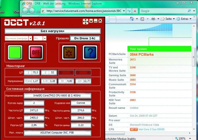 At rest, OCCT shows that AI NOS overclocks the computer by 2.96%. In PCMark Vantage, the computer scored 3544 points, which is 8% more than it was before overclocking. Although it’s hard to believe, even the latest Core i7 processor from Intel depends on the BIOS chip (Basic Input-Output System). ), which appeared at the dawn of the development of x86-compatible computers. The main function of the BIOS is to initialize devices connected to the motherboard after turning on the computer. The BIOS checks their functionality, sets some low-level operating parameters (system bus frequency, various voltages, etc.) and after that transfers control to the operating system.
Overclocking a computer from BIOS Setup is the most reliable and effective, but not every computer user can understand all the settings of a modern BIOS. We'll show you how to do this from the Windows operating system and get an extra 20% performance. You will find all the programs necessary for this on the DVD included with the magazine or in the Download section on the website.
PREPARATION: collecting information about the motherboard
Before proceeding with active actions, it is necessary to clarify the characteristics of the motherboard, processor, RAM and the current settings of these components. This must be done in order to have an idea of the maximum operating frequency and voltage that can be applied to the microcircuits, their thermal package and other important parameters. Otherwise, as a result of rash actions, you risk damaging expensive components. That is why motherboard manufacturers record not only drivers on the optical discs included with their products, but also various applications that can provide the user with all the necessary information.
If you cannot find your disk with drivers and utilities or there are no such applications on it, then use the CPU-Z program, which is on our DVD, as an alternative. After installing and launching it, you will be able to find out the model of the installed processor and its clock frequency, as well as such important parameters for overclocking as the multiplier and the system bus frequency (related FSB).
Go to the Mainboard tab to determine the BIOS version and model of the chipset installed on the motherboard. The “Memory” and “SPD” tabs will tell you everything you need to know about RAM modules. We also recommend taking screenshots of all four bookmarks and printing them - this way you can view this data at any time.
We back up data and control the temperature
Overclocking can lead to component damage and data loss. Below we will tell you what you need to do to protect yourself from these risks.
Data backup. If the computer does not boot after overclocking, resetting the BIOS settings most often helps. To do this, you need to find a special jumper on the board that allows you to reset the settings using a jumper, or remove the battery powering the BIOS for a few minutes. However, in some cases there is a danger of data loss, so before overclocking you should save all important information - this can be done either manually or using special utilities - for example Norton Ghost or Nero BackltUp.
Temperature control. There is another danger - overheating. Therefore, before overclocking your computer, you need to install one or more monitoring programs. If PC components overheat, their lifespan will be shortened. In addition, if exposed to extreme heat, they may fail. In BIOS Setup, which you can enter by pressing the “Del” key after turning on the computer, there is a section that allows you to view the processor temperature and fan speed. It is usually called “Hardware Monitor”, “PC Health Status”, etc.
To check the temperature of the main components of your computer under load, we recommend using the SpeedFan utility, which can be found on our DVD.
Install it and switch to Russian in the “Configure | Options | Language | Russian". The “Indicators” section displays data on the rotation speed of coolers and the temperature of the main devices, as well as the values of various voltages. The amount of data displayed depends on the motherboard model.
If you do not see this information, then the installed board is not supported by the program.
To monitor the status of the hard drive, SpeedFan provides a “S.M.A.R.T.” tab. However, it did not work on our test computer running Windows Vista Ultimate. If the same thing happens to you, install the similar HDDIife program from our DVD. In Vista, you can embed this program into the sidebar, but it will not display all the information there.
Performance measurement. You'll need to install another program that measures your computer's overall performance. For Windows XP, use the test package RSMagk 05, and for Vista - RSMagk Vantage. These programs can be found on the Internet at the developer's website at www.futuremark.com.
Once launched, you will need to register your free copy via email.
Install RSMagk, launch it and click the “Run Benchmark” button. The program will begin running a series of tests and measure the speed of your computer during various tasks that a typical computer user performs, such as playing HD video, editing photos, playing games, and surfing the Internet. During this procedure, do not touch the mouse and keyboard, as this may lead to incorrect results. Upon completion of the test, a number will be displayed on the screen characterizing the overall performance of the PC. The higher it is, the faster the computer works. It can be compared with what you get after overclocking.
UPDATE: Newer versions of drivers and BIOS are almost always better than older ones
After completing the steps described above, you need to take one more preparatory step - update the BIOS and drivers of the motherboard and video card. You should not neglect this, as new firmware and drivers can work a real miracle.
Motherboard manufacturers offer various tools for updating the BIOS. On our test computer with an ASUS motherboard, we used the ASUS Update Tool, which automatically finds and downloads the new BIOS version from the manufacturer's website, and then updates it directly from Windows. Before flashing, do not forget to make a backup copy of the old BIOS.
Advice. If the motherboard manufacturer does not offer such utilities, then you should use UniFlash and Dr. DOS BIOS Boot Disk, which can be downloaded from www.wimsbios.com/biosutil.jsp.
To collect information about other installed devices, use the Everest Home Edition program, which you will find on our website at: http://download.chip.eu/ru.
This utility automatically reads information about all system components. After this, select the “Report Wizard Report” item from the menu, set the profile “Only summary system data” and output it to an HTML file.
The advantages of such a report are that directly from it you can get to the manufacturers’ websites using built-in links. Check if there are new versions of drivers for your devices on the manufacturers' website and install them. After that, measure your computer's speed again using the PCMark test suite. On our computer, the final result increased from 3260 to 3566 points. Thus, the performance increase after updating drivers and BIOS was approximately 9%.
ON AUTOMATIC: overclocking using special utilities
Now it's time to start overclocking.
Almost all motherboard manufacturers offer utilities and special sections in BIOS Setup, with which you can overclock your computer automatically, without manually setting all the parameters. CHIP will tell you how this is done using the ASUS P5B motherboard as an example. In other cases, the sequence of actions is almost the same.
If you decide to overclock your computer from Windows, you will need a special utility from the motherboard manufacturer, such as Guru OS (Abit), Easy Tune (Gigabyte) or, in our case, AI Suite (ASUS).
To allow AI Suite to increase the processor clock speed automatically, go to the “AI NOS” section. Select the “Manual” option in “NOS Mode” and set “Sensitivity” to “Auto”. After this, the utility will be able to automatically increase the processor clock frequency as the load on it increases. You must restart your computer for the changes to take effect. Next you should go to BIOS Setup and set it in the “Advanced | JumperFree Configuration" option "Ai Tuning" to "AI NOS" and "NOS Mode" to "Auto". Then you need to save the settings and boot into Windows.
Now check how the computer behaves when the ASUS utility overclocks the processor. To do this, install the OSST utility, which can be downloaded at: www.ocbase.com/perestroika_en.
Once launched, select the “Manual (Continuous)” and “Mix” options. Click the “On” button and test your computer for fault tolerance for 15 minutes. If no errors are detected during the test, the overclocking was successful.
Advice. If the operating system does not boot after overclocking, you can roll back the changes made in the BIOS in the “Advanced | JumperFree Configuration | AI Tuning".
OVERCALLING WITHOUT SAVINGS: disabling energy-saving technologies
If the computer has passed the fault tolerance test, you need to measure how much its performance has increased after all the manipulations performed. In our case, the result was quite good. However, we are not going to stop there just yet, since the 3780 points scored in PCMark Vantage is still not enough for us. If you are also not satisfied with the achieved result, disabling some settings in the BIOS that may negatively affect performance will help.
First you need to go to the “Advanced | CPU Configuration" and disable the "C1E Support" parameter. This feature reduces the processor's power consumption by reducing the voltage supplied to it (VCore) and thereby limiting the maximum frequency of its operation.
Search in "Chipset | Northbridge Configuration" item "PEG Link Mode" and switch its value to "Auto". With other values of this setting, it increases the clock speed of the PCi Express bus by up to 15%. Double overclocking can cause your computer to become unstable.
After these manipulations, the result in PCMark Vantage increased to 3814 points. We were unable to achieve the maximum possible overclocking of the test PC (20%, 3912 points) using AI NOS, but the system worked stably.
With such a small increase in clock speed, there is no need to deal with overheating. Next, we'll show you how to increase productivity even further, but this comes with some risks.
FOR PROFESSIONALS ONLY: to the limit
The risk and danger of component failure is associated with a real increase in productivity - from 30% and above. However, whether such extreme overclocking makes sense is up to you to decide. In any case, it leads to reduced component life and investment in highly efficient air or water cooling. One way or another, the pursuit of every percentage of performance forces you to use even the farthest corners of the BIOS.
When manually overclocking, the clock frequency of the system bus is most often increased, thereby increasing the performance of all system components. We tried this method. However, before you do this, you need to make some important changes to the BIOS.
Preparing the system. Install in the "Advanced | JumperFree Configuration" value of the "Ai Tuning" item to "Manual". Manually set the frequency of the PCI and PCI Express buses. Set the “PCI Express Frequency” and “PCI Clock Synchronization Mode” parameters to 100 and 33.33, respectively. You also need to set the memory frequency. Select the minimum value in the “DRAM Frequency” field (on our ASUS P5B motherboard - “DDR2-533 Mhz”). After increasing the system bus clock frequency, it will need to be changed to the original one.
Also slightly increase the voltage supplied to the memory chips. The nominal voltage of our memory modules is 1.8 V (standard for DDR2), we increased it using the “Memory Voltage” item to 1.9 V. Go to the “Advanced | Chipset | Northbridge Configuration". In the “Configure DRAm Timing by SPD” subsection, set the value to “Disabled” and change the following values: CAS Latency: 5, RAS# to CAS# Delay: 5, RAS# Precharge: 5, RAS# Activate: 15. Leave the remaining settings unchanged or set to "Auto".
Now the most important thing: since the processor will operate at a higher frequency, it will need a higher supply voltage.
But which one? If you overdo it, the processor may overheat or even burn out.
If cooling is poor, its service life will be significantly reduced. If you set the value too low, the computer will become unstable.
Therefore, we recommend doing the following: find out the rated voltage of your processor model (using CPU-Z or on the Internet), go to a website with a processor overclocking database (for example, www.overclockers.ru) and look at the overclocking statistics for this device. Please note that each individual processor instance is unique in its own way, so you should not immediately display the values found on the Internet. Raise the tension gradually. For our test dual-core CPU (Core 2 Duo E6600), a voltage exceeding 1.45 V can be considered dangerous, especially when using conventional cooling.
Overclocking your computer. Install in BIOS under “Advanced | JumperFree Configuration | FSB Frequency" value, which will be approximately 20 MHz higher than the nominal one. After this, conduct a fault tolerance test using the OSST utility in Windows. Keep an eye on the processor temperature. In Windows, this can be done using the AI Suite, SpeedFan or OSST programs. The processor temperature should not exceed 65–70 °C. Higher values are dangerous.
If the system is stable, raise the “FSB Frequency” a little more. If problems occur, reduce the value in 10 MHz steps until Windows runs without errors.
Memory optimization. When you determine the optimal clock speed level at which the system runs stable and does not overheat, change the “Advanced | Chipset North Bridge Configuration" parameters for memory modules. Reduce the "CAS Fatency" value to "3" and try to start Windows. If the operating system does not boot, change it to “4”. You also need to change “RAS to CAS Delay” and “RAS Precharge”. For "RAS Activate to Precharge" enter "10". The basic principle: the lower the value of these parameters, called timings or memory delays, the faster it works. However, not all memory modules can operate with low latencies. To be sure, you can spin up the system unit and examine the memory chips - usually they have a sticker on them indicating the values of the rated voltage and delays.
Result.
We were able to manually increase the processor clock speed from 2.4 to 3.058 GHz. This represents a 27% increase in performance, or up to a PCMark Vantage score of 3,983. It is impossible to achieve more without replacing the cooling system. After such overclocking, some games began to run noticeably faster.
Overclocking a video card
The video card is equipped with BIOS, memory and processor. CHIP will help increase the performance of a video adapter using the example of a graphics card with an NVIDIA chip.
On boards with AMD chips this is done in a similar way.
Preparing tools. To overclock a video card by editing the BIOS, you will need special utilities - NiBiTor for NVIDIA boards or ATI BIOS Editor and RaBiT for AMD boards. In addition, you need a benchmark package to measure performance: 3DMark 0b for Windows XP or 3DMark Vantage for Vista. Install a performance measurement program and take benchmark measurements. As with the motherboard, these will serve as reference points for you. The NVIDIA GeForce 8800 GTS we used before overclocking scored 8760 points.
Save the video card BIOS. If you have a video card based on an NVIDIA GPU, install the NiBiTor program, which can be found on our DVD.
Go to the “Tools | Read BIOS | Select Device" and read the BIOs of the graphics card. Now use "Tools | Read BIOS | Read into file", save the ROM file to your hard drive and finally using the command "File | Open BIOS" open the file you saved in NiBiTor. You should now see graphics card details.
We increase the frequency. Increasing the clock speed of the graphics card through the BIOS is more dangerous than the same procedure with the motherboard. If something goes wrong, you will no longer be able to get into the NiBiTor program and roll back changes without a PCI video card. As an option, we suggest you download a ready-made file of a tested BIOS version from the website www.mvktech.net or overclock the video card without editing the BIOS using the RivaTuner utility (www.nvworld.ru). To flash the BIOS, you will need to create a bootable MS-DOS floppy disk (www.bootdisk.com). You need to save the modified BIOS and the nvflash.exe utility on it. Start the computer from the floppy disk and replace the graphics card BIOS using nvflash.
Result.
After overclocking, our test system scored 9836 in 3DMark, which corresponds to a 10 percent increase in performance. The core clock frequency increased from 515 to 570 MHz.
On disk: utilities for monitoring and overclocking
CPU-Z - details about the CPU, RAM and motherboard.
SpeedFan - monitoring of various temperatures, voltages and fan speeds.
HDDIife is a program for monitoring the status of hard drives.
AMD OverDrive is a program for overclocking computers with AMD components.
NiBiTor is a BIOS editor for video cards based on NVIDIA GPUs.