Choosing which over-the-air antenna is better. Selecting a TV antenna
Once upon a time, a good television antenna was in short supply; purchased ones did not differ in quality and durability, to put it mildly. Making an antenna for a “box” or “coffin” (an old tube TV) with your own hands was considered a sign of skill. Interest in homemade antennas continues to this day. There is nothing strange here: the conditions for TV reception have changed dramatically, and manufacturers, believing that there is and will not be anything significantly new in the theory of antennas, most often adapt electronics to long-known designs, without thinking about the fact that The main thing for any antenna is its interaction with the signal on the air.
What has changed on air?
Firstly, Almost the entire volume of TV broadcasting is currently carried out in the UHF range. First of all, for economic reasons, it greatly simplifies and reduces the cost of the antenna-feeder system of transmitting stations, and, more importantly, the need for its regular maintenance by highly qualified specialists engaged in hard, harmful and dangerous work.
Second - TV transmitters now cover almost all more or less populated areas with their signal, and a developed communication network ensures the delivery of programs to the most remote corners. There, broadcasting in the habitable zone is provided by low-power, unattended transmitters.
Third, the conditions for the propagation of radio waves in cities have changed. On the UHF, industrial interference leaks in weakly, but reinforced concrete high-rise buildings are good mirrors for them, repeatedly reflecting the signal until it is completely attenuated in an area of seemingly reliable reception.
Fourth - There are a lot of TV programs on air now, dozens and hundreds. How diverse and meaningful this set is is another question, but counting on receiving 1-2-3 channels is now pointless.
Finally, digital broadcasting has developed. The DVB T2 signal is a special thing. Where it still exceeds the noise even just a little, by 1.5-2 dB, the reception is excellent, as if nothing had happened. But a little further or to the side - no, it’s cut off. Digital is almost insensitive to interference, but if there is a mismatch with the cable or phase distortion anywhere in the path, from the camera to the tuner, the picture can crumble into squares even with a strong clean signal.
Antenna requirements
In accordance with the new reception conditions, the basic requirements for TV antennas have also changed:
- Its parameters such as the directivity coefficient (DAC) and the protective action coefficient (PAC) are now of no decisive importance: modern air is very dirty, and along the tiny side lobe of the directional pattern (DP), at least some interference will get through, and You need to fight it using electronic means.
- In return, the antenna's own gain (GA) becomes especially important. An antenna that “catches” the air well, rather than looking at it through a small hole, will provide a reserve of power for the received signal, allowing the electronics to clear it of noise and interference.
- A modern television antenna, with rare exceptions, must be a range antenna, i.e. its electrical parameters must be preserved naturally, at the level of theory, and not squeezed into acceptable limits through engineering tricks.
- The TV antenna must be matched with the cable over its entire operating frequency range without additional matching and balancing devices (MCD).
- The amplitude-frequency response of the antenna (AFC) should be as smooth as possible. Sharp surges and dips are certainly accompanied by phase distortions.
The last 3 points are determined by the requirements for receiving digital signals. Customized, i.e. Working theoretically at the same frequency, antennas can be “stretched” in frequency, for example. antennas of the “wave channel” type on the UHF with an acceptable signal-to-noise ratio capture channels 21-40. But their coordination with the feeder requires the use of USSs, which either strongly absorb the signal (ferrite) or spoil the phase response at the edges of the range (tuned). And such an antenna, which works perfectly on analogue, will receive “digital” poorly.
In this regard, from all the great variety of antennas, this article will consider TV antennas, available for self-production, of the following types:
- Frequency independent (all-wave)– does not have high parameters, but is very simple and cheap, it can be done in literally an hour. Outside the city, where the airwaves are cleaner, it will be able to receive digital or a fairly powerful analogue not a short distance from the television center.
- Range log-periodic. Figuratively speaking, it can be likened to a fishing trawl, which sorts the prey during fishing. It is also quite simple, fits perfectly with the feeder throughout its entire range, and does not change its parameters at all. The technical parameters are average, so it is more suitable for a summer residence, and in the city as a room.
- Several modifications of the zigzag antenna, or Z-antennas. In the MV range, this is a very solid design that requires considerable skill and time. But on the UHF, due to the principle of geometric similarity (see below), it is so simplified and shrunk that it can well be used as a highly efficient indoor antenna under almost any reception conditions.
Note: The Z-antenna, to use the previous analogy, is a frequent dragster that scoops up everything in the water. As the air became littered, it fell out of use, but with the development of digital TV, it was once again on the high horse - throughout its entire range, it is just as perfectly coordinated and keeps the parameters as a “speech therapist.”
Precise matching and balancing of almost all antennas described below is achieved by laying the cable through the so-called. zero potential point. It has special requirements, which will be discussed in more detail below.
About vibrator antennas
In the frequency band of one analog channel, up to several dozen digital ones can be transmitted. And, as already said, the digital works with an insignificant signal-to-noise ratio. Therefore, in places very remote from the television center, where the signal of one or two channels barely reaches, the good old wave channel (AVK, wave channel antenna), from the class of vibrator antennas, can be used for receiving digital TV, so at the end we will devote a few lines and to her.
About satellite reception
There is no point in making a satellite dish yourself. You still need to buy a head and a tuner, and behind the external simplicity of the mirror lies a parabolic surface of oblique incidence, which not every industrial enterprise can produce with the required accuracy. The only thing homemade people can do is set up a satellite dish, about that.
About antenna parameters
Accurate determination of the antenna parameters mentioned above requires knowledge of higher mathematics and electrodynamics, but it is necessary to understand their meaning when starting to manufacture an antenna. Therefore, we will give somewhat rough, but still clarifying definitions (see figure on the right):

- KU - the ratio of the signal power received by the antenna on the main (main) lobe of its RP to its same power received in the same place and at the same frequency by an omnidirectional, circular, DP antenna.
- KND is the ratio of the solid angle of the entire sphere to the solid angle of the opening of the main lobe of the DN, assuming that its cross-section is a circle. If the main petal has different sizes in different planes, you need to compare the area of the sphere and its cross-sectional area of the main petal.
- SCR is the ratio of the signal power received at the main lobe to the sum of the interference powers at the same frequency received by all secondary (back and side) lobes.
Notes:
- If the antenna is a band antenna, the powers are calculated at the frequency of the useful signal.
- Since there are no completely omnidirectional antennas, a half-wave linear dipole oriented in the direction of the electric field vector (according to its polarization) is taken as such. Its QU is considered equal to 1. TV programs are transmitted with horizontal polarization.
It should be remembered that CG and KNI are not necessarily interrelated. There are antennas (for example, “spy” - single-wire traveling wave antenna, ABC) with high directivity, but single or lower gain. These look into the distance as if through a diopter sight. On the other hand, there are antennas, e.g. Z-antenna, which combines low directivity with significant gain.
About the intricacies of manufacturing
All antenna elements through which useful signal currents flow (specifically, in the descriptions of individual antennas) must be connected to each other by soldering or welding. In any prefabricated unit in the open air, the electrical contact will soon be broken, and the parameters of the antenna will deteriorate sharply, up to its complete unusability.
This is especially true for points of zero potential. In them, as experts say, there is a voltage node and a current antinode, i.e. its greatest value. Current at zero voltage? Nothing surprising. Electrodynamics has moved as far from Ohm's law on direct current as the T-50 has gone from a kite.
Places with zero potential points for digital antennas are best made bent from solid metal. A small “creeping” current in welding when receiving the analogue in the picture will most likely not affect it. But, if a digital signal is received at the noise level, then the tuner may not see the signal due to the “creep”. Which, with pure current at the antinode, would give stable reception.
About cable soldering
The braid (and often the central core) of modern coaxial cables is made not of copper, but of corrosion-resistant and inexpensive alloys. They solder poorly and if you heat them for a long time, you can burn out the cable. Therefore, you need to solder the cables with a 40-W soldering iron, low-melting solder and with flux paste instead of rosin or alcohol rosin. There is no need to spare the paste; the solder immediately spreads along the veins of the braid only under a layer of boiling flux.

Types of antennas
All-wave
An all-wave (more precisely, frequency-independent, FNA) antenna is shown in Fig. It consists of two triangular metal plates, two wooden slats, and a lot of enameled copper wires. The diameter of the wire does not matter, and the distance between the ends of the wires on the slats is 20-30 mm. The gap between the plates to which the other ends of the wires are soldered is 10 mm.
Note: Instead of two metal plates, it is better to take a square of one-sided foil fiberglass with triangles cut into copper.
The width of the antenna is equal to its height, the opening angle of the blades is 90 degrees. The cable routing diagram is shown there in Fig. The point marked in yellow is the point of quasi-zero potential. There is no need to solder the cable braid to the fabric in it; just tie it tightly, and the capacity between the braid and the fabric will be enough for matching.
The CHNA, stretched in a window 1.5 m wide, receives all meter and DCM channels from almost all directions, except for a dip of about 15 degrees in the plane of the canvas. This is its advantage in places where it is possible to receive signals from different television centers; it does not need to be rotated. Disadvantages - single gain and zero gain, therefore, in the interference zone and outside the zone of reliable reception, the CNA is not suitable.
Note : There are other types of CNA, for example. in the form of a two-turn logarithmic spiral. It is more compact than the CNA made of triangular sheets in the same frequency range, therefore it is sometimes used in technology. But in everyday life this does not provide any advantages, it is more difficult to make a spiral CNA, and it is more difficult to coordinate with a coaxial cable, so we are not considering it.
Based on the CHNA, the once very popular fan vibrator (horns, flyer, slingshot) was created, see fig. Its directivity factor and coefficient of performance are something around 1.4 with a fairly smooth frequency response and linear phase response, so it would be suitable for digital use even now. But - it works only on HF (channels 1-12), and digital broadcasting is on UHF. However, in the countryside, with an elevation of 10-12 m, it may be suitable for receiving an analogue. Mast 2 can be made of any material, but fastening strips 1 are made of a good non-wetting dielectric: fiberglass or fluoroplastic with a thickness of at least 10 mm.

Beer all-wave

The all-wave antenna made from beer cans is clearly not the fruit of the hangover hallucinations of a drunken radio amateur. This is truly a very good antenna for all reception situations, you just need to do it right. And it’s extremely simple.
Its design is based on the following phenomenon: if you increase the diameter of the arms of a conventional linear vibrator, then its operating frequency band expands, but other parameters remain unchanged. In long-distance radio communications, since the 20s, the so-called Nadenenko's dipole based on this principle. And beer cans are just the right size to serve as the arms of a vibrator on the UHF. In essence, the CHNA is a dipole, the arms of which expand indefinitely to infinity.
The simplest beer vibrator made of two cans is suitable for indoor analogue reception in the city, even without coordination with the cable, if its length is no more than 2 m, on the left in Fig. And if you assemble a vertical in-phase array from beer dipoles with a step of half a wave (on the right in the figure), match it and balance it using an amplifier from a Polish antenna (we will talk about it later), then thanks to the vertical compression of the main lobe of the pattern, such an antenna will give good CU.
The gain of the “tavern” can be further increased by adding a CPD at the same time, if a mesh screen is placed behind it at a distance equal to half the grid pitch. The beer grill is mounted on a dielectric mast; The mechanical connections between the screen and the mast are also dielectric. The rest is clear from the following. rice.

Note: the optimal number of lattice floors is 3-4. With 2, the gain in gain will be small, and more is difficult to coordinate with the cable.
Video: making a simple antenna from beer cans
"Speech therapist"
A log-periodic antenna (LPA) is a collecting line to which halves of linear dipoles (i.e., pieces of conductor a quarter of the operating wavelength) are alternately connected, the length and distance between which vary in geometric progression with an index less than 1, in the center in Fig. The line can be either configured (with a short circuit at the end opposite to the cable connection) or free. An LPA on a free (unconfigured) line is preferable for digital reception: it comes out longer, but its frequency response and phase response are smooth, and the matching with the cable does not depend on frequency, so we will focus on it.

The LPA can be manufactured for any predetermined frequency range, up to 1-2 GHz. When the operating frequency changes, its active region of 1-5 dipoles moves back and forth along the canvas. Therefore, the closer the progression indicator is to 1, and accordingly the smaller the antenna opening angle, the greater the gain it will give, but at the same time its length increases. At UHF, 26 dB can be achieved from an outdoor LPA, and 12 dB from a room LPA.
LPA can be said to be an ideal digital antenna based on its totality of qualities, so let’s look at its calculation in a little more detail. The main thing you need to know is that an increase in the progression indicator (tau in the figure) gives an increase in gain, and a decrease in the LPA opening angle (alpha) increases the directivity. A screen is not needed for the LPA; it has almost no effect on its parameters.
Calculation of digital LPA has the following features:
- They start it, for the sake of frequency reserve, with the second longest vibrator.
- Then, taking the reciprocal of the progression index, the longest dipole is calculated.
- After the shortest dipole based on the given frequency range, another one is added.
Let's explain with an example. Let's say our digital programs are in the range of 21-31 TVK, i.e. at 470-558 MHz in frequency; wavelengths, respectively, are 638-537 mm. Let’s also assume that we need to receive a weak noisy signal far from the station, so we take the maximum (0.9) progression rate and the minimum (30 degrees) opening angle. For the calculation, you will need half the opening angle, i.e. 15 degrees in our case. The opening can be further reduced, but the length of the antenna will increase exorbitantly, in cotangent terms.
We consider B2 in Fig: 638/2 = 319 mm, and the arms of the dipole will be 160 mm each, you can round up to 1 mm. The calculation will need to be carried out until you get Bn = 537/2 = 269 mm, and then calculate another dipole.
Now we consider A2 as B2/tg15 = 319/0.26795 = 1190 mm. Then, through the progression indicator, A1 and B1: A1 = A2/0.9 = 1322 mm; B1 = 319/0.9 = 354.5 = 355 mm. Next, sequentially, starting with B2 and A2, we multiply by the indicator until we reach 269 mm:
- B3 = B2*0.9 = 287 mm; A3 = A2*0.9 = 1071 mm.
- B4 = 258 mm; A4 = 964 mm.
Stop, we are already less than 269 mm. We check whether we can meet the gain requirements, although it is clear that we can’t: to get 12 dB or more, the distances between the dipoles should not exceed 0.1-0.12 wavelengths. In this case, for B1 we have A1-A2 = 1322 – 1190 = 132 mm, which is 132/638 = 0.21 wavelengths of B1. We need to “pull up” the indicator to 1, to 0.93-0.97, so we try different ones until the first difference A1-A2 is reduced by half or more. For a maximum of 26 dB, you need a distance between dipoles of 0.03-0.05 wavelengths, but not less than 2 dipole diameters, 3-10 mm at UHF.
Note: cut off the rest of the line behind the shortest dipole; it is needed only for calculations. Therefore, the actual length of the finished antenna will be only about 400 mm. If our LPA is external, this is very good: we can reduce the opening, obtaining greater directionality and protection from interference.
Video: antenna for digital TV DVB T2
About the line and the mast
The diameter of the tubes of the LPA line on the UHF is 8-15 mm; the distance between their axes is 3-4 diameters. Let’s also take into account that thin “lace” cables give such attenuation per meter on the UHF that all antenna-amplification tricks will come to naught. You need to take a good coaxial for an outdoor antenna, with a shell diameter of 6-8 mm. That is, the tubes for the line must be thin-walled, seamless. You cannot tie the cable to the line from the outside; the quality of the LPA will drop sharply.
It is necessary, of course, to attach the outer prop to the mast by the center of gravity, otherwise the small windage of the prop will turn into a huge and shaking one. But it is also impossible to connect a metal mast directly to the line: you need to provide a dielectric insert of at least 1.5 m in length. The quality of the dielectric does not play a big role here; oiled and painted wood will do.
About the Delta antenna
If the UHF LPA is consistent with the cable amplifier (see below, about Polish antennas), then the arms of a meter dipole, linear or fan-shaped, like a “slingshot”, can be attached to the line. Then we will get a universal VHF-UHF antenna of excellent quality. This solution is used in the popular Delta antenna, see fig.

Delta antenna
Zigzag on air
A Z-antenna with a reflector gives the same gain and gain as the LPA, but its main lobe is more than twice as wide horizontally. This can be important in rural areas when there is TV reception from different directions. And the decimeter Z-antenna has small dimensions, which is essential for indoor reception. But its operating range is theoretically not unlimited; frequency overlap while maintaining parameters acceptable for the digital range is up to 2.7.

The design of the MV Z-antenna is shown in Fig; The cable route is highlighted in red. There in the lower left there is a more compact ring version, colloquially known as a “spider”. It clearly shows that the Z-antenna was born as a combination of a CNA with a range vibrator; There is also something of a rhombic antenna in it, which does not fit into the theme. Yes, the “spider” ring does not have to be wooden, it can be a metal hoop. "Spider" receives 1-12 MV channels; The pattern without a reflector is almost circular.
The classic zigzag works either on 1-5 or 6-12 channels, but for its manufacture you only need wooden slats, enameled copper wire with d = 0.6-1.2 mm and several scraps of foil fiberglass, so we give the dimensions in fraction for 1-5/6-12 channels: A = 3400/950 mm, B, C = 1700/450 mm, b = 100/28 mm, B = 300/100 mm. At point E there is zero potential; here you need to solder the braid to a metallized support plate. Reflector dimensions, also 1-5/6-12: A = 620/175 mm, B = 300/130 mm, D = 3200/900 mm.
The range Z-antenna with a reflector gives a gain of 12 dB, tuned to one channel - 26 dB. To build a single-channel one based on a range zigzag, you need to take the side of the square of the canvas in the middle of its width at a quarter of the wavelength and recalculate all other dimensions proportionally.
Folk Zigzag
As you can see, the MV Z-antenna is a rather complex structure. But its principle shows itself in all its glory on the UHF. The UHF Z-antenna with capacitive inserts, combining the advantages of the “classics” and the “spider”, is so easy to make that even in the USSR it earned the title of folk antenna, see fig.

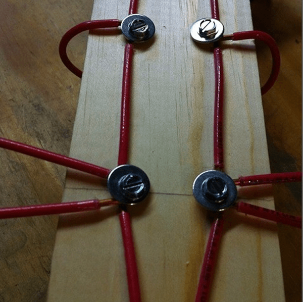
Material – copper tube or aluminum sheet with a thickness of 6 mm. The side squares are solid metal or covered with mesh, or covered with a tin. In the last two cases, they need to be soldered along the circuit. The coax cannot be bent sharply, so we guide it so that it reaches the side corner, and then does not go beyond the capacitive insert (side square). At point A (zero potential point), we electrically connect the cable braid to the fabric.
Note: aluminum cannot be soldered with conventional solders and fluxes, so “folk” aluminum is suitable for outdoor installation only after sealing the electrical connections with silicone, since everything in it is screwed.
Video: example of a double triangle antenna
Wave channel

The wave channel antenna (AWC), or Udo-Yagi antenna, available for self-production, is capable of giving the highest gain, directivity factor and efficiency factor. But it can only receive digital signals on UHF on 1 or 2-3 adjacent channels, because belongs to the class of highly tuned antennas. Its parameters deteriorate sharply beyond the tuning frequency. It is recommended to use AVK under very poor reception conditions, and make a separate one for each TVK. Fortunately, this is not very difficult - AVK is simple and cheap.
The operation of the AVK is based on “raking” the electromagnetic field (EMF) of the signal to the active vibrator. Externally small, lightweight, with minimal windage, the AVK can have an effective aperture of dozens of wavelengths of the operating frequency. Directors (directors) that are shortened and therefore have capacitive impedance (impedance) direct the EMF to the active vibrator, and the reflector (reflector), elongated, with inductive impedance, throws back to it what has slipped past. Only 1 reflector is needed in an AVK, but there can be from 1 to 20 or more directors. The more there are, the higher the gain of the AVC, but the narrower its frequency band.
From interaction with the reflector and directors, the wave impedance of the active (from which the signal is taken) vibrator drops the more, the closer the antenna is tuned to the maximum gain, and coordination with the cable is lost. Therefore, the active dipole AVK is made into a loop, its initial wave impedance is not 73 Ohms, like a linear one, but 300 Ohms. At the cost of reducing it to 75 Ohms, an AVK with three directors (five-element, see the figure on the right) can be adjusted to almost a maximum gain of 26 dB. A characteristic pattern for AVK in the horizontal plane is shown in Fig. at the beginning of the article.
AVK elements are connected to the boom at points of zero potential, so the mast and boom can be anything. Propylene pipes work very well.
Calculation and adjustment of AVK for analog and digital are somewhat different. For analogue, the wave channel must be calculated at the carrier frequency of the image Fi, and for digital – at the middle of the TVC spectrum Fc. Why this is so - unfortunately, there is no room to explain here. For the 21st TVC Fi = 471.25 MHz; Fс = 474 MHz. UHF TVCs are located close to each other at 8 MHz, so their tuning frequencies for AVCs are calculated simply: Fn = Fi/Fс(21 TVCs) + 8(N – 21), where N is the number of the desired channel. Eg. for 39 TVCs Fi = 615.25 MHz, and Fc = 610 MHz.
In order not to write down a lot of numbers, it is convenient to express the dimensions of the AVK in fractions of the operating wavelength (it is calculated as A = 300/F, MHz). The wavelength is usually denoted by the small Greek letter lambda, but since there is no default Greek alphabet on the Internet, we will conventionally denote it by the large Russian L.
The dimensions of the digitally optimized AVK, according to the figure, are as follows:

- P = 0.52L.
- B = 0.49L.
- D1 = 0.46L.
- D2 = 0.44L.
- D3 = 0.43l.
- a = 0.18L.
- b = 0.12L.
- c = d = 0.1L.
If you don’t need a lot of gain, but reducing the size of the AVK is more important, then D2 and D3 can be removed. All vibrators are made of a tube or rod with a diameter of 30-40 mm for 1-5 TVKs, 16-20 mm for 6-12 TVKs and 10-12 mm for UHF.
AVK requires precise coordination with the cable. It is the careless implementation of the matching and balancing device (CMD) that explains most of the failures of amateurs. The simplest USS for AVK is a U-loop made from the same coaxial cable. Its design is clear from Fig. right. The distance between signal terminals 1-1 is 140 mm for 1-5 TVKs, 90 mm for 6-12 TVKs and 60 mm for UHF.
Theoretically, the length of the knee l should be half the length of the working wave, and this is what is indicated in most publications on the Internet. But the EMF in the U-loop is concentrated inside the cable filled with insulation, so it is necessary (for numbers - especially mandatory) to take into account its shortening factor. For 75-ohm coaxials it ranges from 1.41-1.51, i.e. l you need to take from 0.355 to 0.330 wavelengths, and take exactly so that the AVK is an AVK, and not a set of pieces of iron. The exact value of the shortening factor is always in the cable certificate.
Recently, the domestic industry has begun to produce reconfigurable AVK for digital, see Fig. The idea, I must say, is excellent: by moving the elements along the boom, you can fine-tune the antenna to local reception conditions. It is better, of course, for a specialist to do this - the element-by-element adjustment of the AVC is interdependent, and an amateur will certainly get confused.

About “Poles” and amplifiers
Many users have Polish antennas, which previously received analogue decently, but refuse to accept digital - they break or even disappear completely. The reason, I beg your pardon, is the obscene commercial approach to electrodynamics. Sometimes I feel ashamed for my colleagues who have concocted such a “miracle”: the frequency response and phase response resemble either a psoriasis hedgehog or a horse’s comb with broken teeth.
The only good thing about the Poles is their antenna amplifiers. Actually, they do not allow these products to die ingloriously. Belt amplifiers are, firstly, low-noise, broadband. And, more importantly, with a high-impedance input. This allows, at the same strength of the EMF signal on the air, to supply several times more power to the tuner input, which makes it possible for the electronics to “rip out” a number from very ugly noise. In addition, due to the high input impedance, the Polish amplifier is an ideal USS for any antennas: whatever you attach to the input, the output is exactly 75 Ohms without reflection or creep.
However, with a very poor signal, outside the zone of reliable reception, the Polish amplifier no longer works. Power is supplied to it via a cable, and power decoupling takes away 2-3 dB of the signal-to-noise ratio, which may not be enough for the digital signal to go right into the outback. Here you need a good TV signal amplifier with separate power supply. It will most likely be located near the tuner, and the control system for the antenna, if required, will have to be made separately.

The circuit of such an amplifier, which has shown almost 100% repeatability even when implemented by novice radio amateurs, is shown in Fig. Gain adjustment – potentiometer P1. The decoupling chokes L3 and L4 are standard purchased ones. Coils L1 and L2 are made according to the dimensions in the wiring diagram on the right. They are part of signal bandpass filters, so small deviations in their inductance are not critical.
Despite the widespread Internetization of the population in our country, a good half of our compatriots prefer to spend their free time in front of the blue TV screen. The difference between a city resident and a rural resident in terms of TV broadcasting is very significant. If the former, as a rule, use TV services through dedicated lines (cable TV), then the latter are difficult to do without an outdoor antenna.
Let's try to figure out how to choose the right outdoor antenna for a TV for a dacha or country house, what types of these devices can be found on sale, and also identify a small list of the most popular and respected owners of the models.
Types of antennas
To begin with, let’s outline the main types of these devices, which differ from each other in functionality, appearance and other equally important features. The final conclusions about the advisability of a purchase should be made based on personal needs and the geolocation of your home.
Satellite dish
The now extremely popular “dishes” do not depend in any way on proximity to television towers, because they broadcast via satellite. In addition, the signal strength of a satellite outdoor TV antenna is not affected by the terrain.

Even the simplest “dish” option, such as offset or direct focus, allows you to easily receive an image in high quality. Here you can add a large number of providers, and at the same time a lot of channels.
Despite the obvious advantages of a satellite outdoor TV antenna over other devices, it also has its own, for some, critical disadvantages. Firstly, it's cost. Here you need to spend money on the “dish” itself, and the worse the terrain (harsh climate, proximity to industrial enterprises that disrupt the signal, etc.), the larger the diameter and the more technologically advanced the device is required, as well as the more expensive it is. Secondly, you will need to buy a receiver for broadcast processing and, in difficult cases, a convector to create an outdoor antenna for a TV with an amplifier. And thirdly, for normal broadcasting it would obviously not be superfluous to have a smart TV capable of producing and “digesting” a high-quality picture.
"Polish" antennas
This is the simplest, most unpretentious and cheapest device of which there is a sea on the electronics market. It has a lattice frame with antennae and is perfect for ordinary cottages. With this antenna you can catch a dozen local channels, including ORT and NTV. In addition, having a tool at your disposal, you can easily make a semblance of the original with your own hands.

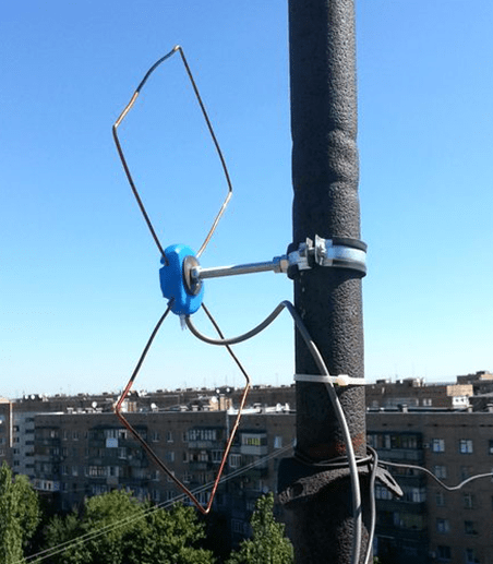
Outdoor antennas for a TV of this type are placed on the house, roof, poles and other hills, with the central part directed towards the TV tower. The latter should be no further than 30 km from you. If the local terrain is diluted with trees, hillocks, waste heaps or other obstacles that disrupt the signal, then the outdoor antenna for the TV should be installed as high as possible. In difficult cases, a smart amplifier will help to stabilize the broadcast and eliminate most interference.
"Polish" antennas with amplification unit
Such devices already come off the assembly line with a built-in amplifier and are called “active”. An outdoor antenna for a TV of this type significantly expands the list of received channels and improves the broadcast quality.
The design of this device consists of several separate blocks, which are arranged in a certain way for maximum signal perception. The internal amplifier allows you to expand the reception range to 80 km, recognizing even the weakest broadcasts (usually with loss of quality). Just as in the previous case, you can make an outdoor antenna for a TV with an amplifier with your own hands. The only thing you will need besides the materials described above is a high-quality converter. Such devices are installed at the highest possible point, that is, on the roof or a homemade pole/pole.
Traveling wave devices (Uda-Yagi)
Antennas of this class have fairly high receiving characteristics and are compact. All main elements of the device are secured to one common boom. In addition, this type of antenna is able to work with several bands, which is very important for remote and hard-to-reach villages, where there are only old towers nearby that broadcast at non-standard frequencies.
Digital antennas
Such devices consist of two parts - a tuner for digital signal processing and an antenna frame that is installed outdoors. The design of the latter is as simple as possible, because the main responsibility for signal reception lies with the tuner. A digital outdoor TV antenna is perfect for those who are comfortable with modern technology, are not afraid of numerous settings/variations in the menu, and whose home is located near the city. Such devices are configured to receive only the main signal and ignore reflected interference well.
Antenna types
In total, there are two types of antennas - passive and active. The first option involves a separate/external converter, and the second - with a built-in amplifier. In terms of signal reception quality, they differ little, but in terms of service life - significantly.

Active devices installed “as is,” that is, without additional protection, will last a little more than a year, because due to bad weather and corrosion, the built-in converter begins to fail. Passive models come with an external amplifier, which can be located at home or somewhere in the attic, so the service life of such antennas is much longer.
The best outdoor antennas for TV
On the domestic electronics market you can find a large number of all kinds of receiving devices of different types and types, where each series or model is adapted to specific signal reception conditions. Therefore, it is very difficult to designate any specific model as the best; many individual factors must be taken into account (geolocation of the house, nearby TV towers, quality of signal transmission, etc.). Well, compiling a list of the best antenna manufacturers that have proven themselves well in the eyes of picky buyers is quite possible.
Delta antennas
The antennas of this company are enviably popular among domestic consumers, especially since the company’s product range is very diverse. On store shelves you can find both narrowly targeted models, which are designed exclusively for meter and decimeter waves, and broadband universal devices.

In addition, the vast majority of antennas from Delta can operate with a digital signal. Connecting and installing the devices is relatively easy; just insert the cable into the connector with the F-amplifier and fix the device at the highest point in the house. The antennas do a good job of receiving and processing the signal even at a considerable distance from the house to the television tower.
Lokus Antennas
The company's product range includes both active (with a built-in converter) and passive models (with an external amplifier). Domestic buyers are especially attracted by the brand’s pricing policy and the very good quality of the products.

The design of the antennas is very simple, and installation does not require any specific tools or preparation. The devices are designed to work simultaneously with two or three TVs, so they are suitable even for large dachas.
Antennas "Harpoon"
Another recognized leader in the production of high-quality antennas in the domestic market. Although prices are affordable, the company’s devices are famous for their “omnivorousness.” Almost any Harpoon model is perfect for areas with uncertain signal reception.

In addition, the good signal selectivity of this brand of antennas significantly relieves the user of interference on the TV screen. One of the critical disadvantages of Harpoon products is their finicky nature to meter waves, so problems may arise when working with outdated TV towers.
Antennas GoldMaster
Despite the more than affordable prices of the products, the devices of this company were distinguished by very good reception in places with terrible signal quality. Judging by user reviews, GoldMaster brand antennas do an excellent job of the task even in remote rural areas: the image on the screen is without “snow”, the picture does not slow down and is not interrupted by neighboring signals.
In addition, the devices can withstand almost any bad weather, be it rain, heavy snow or stormy winds. Let's add here low prices for products and we get a completely optimal country antenna option.
It appeared in Russia relatively recently, but is already quite popular. For example, our region, and this St. Petersburg and Leningrad region, fully covered by digital TV broadcasting, and any summer resident can please himself without any problems by watching channels in good quality, and, moreover, without any subscription fee. Unfortunately, the number of “found” on-air digital channels in individual areas of the Leningrad region may vary. Somewhere there will be 20 of them, and somewhere - only 10. It all depends on how many multiplexes (packages of 10 TV channels, RTRS-1 And RTRS-2) is broadcast by one or another digital transmitter. To date both multiplexes transmitters broadcast to St. Petersburg, Gatchina, Vyborg, Tikhvin and, as buyers tell us, in Volkhov. The situation can change at any moment, because... everything has been built, and the status of the remaining transmitting stations of the second multiplex (RTRS-2) is indicated on the RTRS.RF website as “standby mode”.
Often, customers who come to our store say: “I need a set-top box for 20 channels, otherwise my neighbor has some kind of bad one. It shows only 10 channels". I think from the above, you already understand that the number of digital television channels received does not depend on the DVB-T2 receiver model and its prices.
Of course, based on the experience and statistics we have collected, it cannot be said that all receivers, regardless of the “filling,” process weak DVB-T2 over-the-air signals equally well. However, we can say with confidence that the quality of the received digital signal depends entirely on the television antenna at your disposal. And also, strange as it may seem, both from the TV cable and from the quality of its cutting.
Thus, if with television reception in the city everything is more or less clear and relatively simple, then in order to enjoy watching your favorite TV shows in the country, you should more carefully select an antenna that will be able to provide high-quality reception of the terrestrial DVB-T2 signal in this particular place. And the choice will largely depend on the location of the nearest broadcaster, the signal of which will be “caught” by the antenna.
Antennas for terrestrial digital television.
In general, on-air television broadcasting is carried out on meter (MV/VHF) and decimeter (UHF/UHF) waves. To receive channels in the DVB-T2 digital format, an antenna that is capable of operating in the UHF range is sufficient. Moreover, a digital antenna is no different from a regular one, and the inscriptions on the boxes are like: "DVB-T2 antenna", "Digital television antenna", "Antenna for digital television" etc. – ordinary advertising ploy. Many people already have all-wave TV antennas at their dachas; they may well be suitable for receiving an on-air digital television signal.
Everyone knows very well that antennas can be indoor and outdoor, active (with an amplifier) and passive, purchased and homemade. Giving recommendations for making homemade antennas is not within my competence and the purpose of this article. Here we look at the antennas that you can buy in our store.
Indoor antennas for receiving DVB-T2 signals.
 Indoor UHF antennas are very compact and there is nothing strange in the fact that many people want to use just such antennas in their dachas. Firstly, it’s not noticeable; in winter they don’t “cut it down” like a Christmas tree before the New Year. Secondly, there is no need to climb onto the roof, install a mast, and in general, there is a minimum of effort to secure such devices. But the peculiarity of reception at the dacha is that the DVB-T2 translator can be low-power and at the same time located quite far away, and sometimes even the house is in a lowland. What kind of indoor antenna is this? Reception on it is possible only in a zone of reliable reception, where the level of the on-air digital television signal will be quite high.
Those who want to use an indoor antenna in the country, since hunting is sometimes worse than captivity, can be given fairly universal advice:
 If the translator is visible from your or a nearby summer cottage, even from the roof of a house, then you can try connecting to the DVB-T2 receiver instead of an antenna, for example, a piece of wire or coaxial cable. Select the item in the console menu "Manual settings" channels and set the desired channel (this process is described in any of the receiver reviews on our website). Then, walk around the room with this antenna wire, for example, bring it closer to the window, try to raise it higher to the ceiling, move all the “equipment” to the attic, etc. If at least some minimal, more or less clear, and even more desirable, stable scale readings appear "Power" and/or "Quality", then you can try a directional active (with amplifier) indoor antenna. With a high degree of probability it will “work.”
If an active indoor UHF antenna is used next to a fairly powerful broadcaster, for example within a city, then it is better if there is possibility of gain adjustment. A too strong signal for a DVB-T2 set-top box is just as bad as a weak one.
The statement that in the city you can catch a digital TV signal even as small as a nail is completely wrong. Each specific location of this “receiving nail” will be unique in terms of reception conditions. Even the antenna has to be selected.
Hit 1. Perhaps the best indoor antenna for working with reflected signals in difficult urban conditions.
Video review of antenna Delta 131A.03 - 5v
Video review of antenna Delta 131A.02 - 5v
Indoor antennas undoubtedly have many advantages, but, nevertheless, most often it happens that with all the manipulations with them in the conditions of a summer cottage, no signs of clear reception of an on-air digital DVB-T2 signal can be achieved. In this case, you will not be able to do without an external antenna. And for options when the distance to the nearest broadcaster is tens of kilometers, an external antenna is definitely required.
And the main one question here it will sound like this - which one exactly?
Most likely, you will not be the only owner of a DVB-T2 receiver in your gardening. Take a closer look at the antennas in neighboring areas, to where they are directed. If there is such an opportunity, then talk to the owners, find out how their digital set-top box with such an antenna works. This will certainly help you make your choice.
External antennas for receiving DVB-T2 signals.
As a rule, when choosing an outdoor antenna, the following questions arise:
- Which antenna is best for receiving a digital TV signal in the country?
- Which is better - passive or active?
- Where is the best place to install the antenna?
- Which cable to choose?
 Unfortunately, an exact answer that will be valid in all cases can only be given to the last question. The cable must be of high quality. You should not skimp on it, as a bad cable will negate all the advantages of even the best antenna. The central core should be thick and soft, the screen should consist of foil and copper, preferably tinned, braid, and not just foil. By the way, the highest quality cables use double foil, i.e. foil-film-foil. The cable diameter must be at least 5 millimeters. The easiest way to find accessories for a 6 mm coaxial television cable. However, there is quite a lot of information on the Internet about which cable is better to use and how and how a high-quality branded cable differs from counterfeits.
Now let's try to find answers to other questions that arise when choosing an antenna for receiving terrestrial digital television in the country. I will not delve into the scientific jungle and give sophisticated technical characteristics such as the protective coefficient of the antenna or the directivity coefficient.
The buyer may only be interested in the gain value of an antenna, and even then only when comparing several types of antennas.
As for manufacturers, we generally give preference to antennas manufactured by CJSC "NPP OST", whose products are well known in our country under the brand name "Delta". As well as products of the Saratov Electromechanical Plant "REMO".
 Modern outdoor antennas are made of steel or aluminum. Their forms are different, but The most effective for receiving a DVB-T2 signal are time-tested log-periodic UHF antennas and “wave channel” antennas. As for the gain, then, to put it simply and very primitively, the longer such an antenna is, the more transverse elements it has, the greater its gain, all other things being equal. I repeat, such antennas are perhaps the best option for receiving digital TV in the country. And it is them, mainly, that you can see in our store and on this website.
Hit 2. One of the most popular outdoor antennas in our store. Almost guaranteed results.
Two versions - without amplifier and with amplifier.
Moreover, the numerical values of the reception range indicated in the parameters of some antennas, as a rule, are aimed at high-power transmitters. And in digital terrestrial television broadcasting, both medium and low power transmitters are used. The height of the antenna mast structures is also different. Data for our region is available on this website spb.rtrs.ru. And all this, as well as the terrain and the height of your antenna, also matters. In addition, the range and quality of reception are affected by dozens of other factors, including even the time of year and day.
 In general, if the distance to the nearest translator is 25 km - 30 km, the terrain is flat and there are no 30-meter trees directly in front of the house, then the reception of the digital signal should be reliable, and, most likely, an outdoor antenna without an amplifier (passive) will be suitable.
Anything that does not meet the above conditions can be classified as a zone of uncertain reception. For example, the house may be located in a lowland, the forest may be quite close, etc. In this case, an antenna with an amplifier (active) will help out.
Hit 3. An excellent log periodic antenna with an amplifier for operation at medium distances.
A definite plus is the 5 volt power supply from the DVB-T2 receiver.
However, unfortunately, not everything is very good; there are always some pitfalls. Here too, when purchasing an active antenna, be prepared for the fact that after some time the amplifier will most likely fail and will have to be replaced. Basically, the input stage of the amplifier "crashes" due to static electricity. This can be either a discharge from induced atmospheric static, for example, after a thunderstorm, or one that accumulates, for example, in dry, frosty weather (snow or dust is rubbed by the wind over the antenna).
At first glance, it seems that the problem of the effect of static electricity on an antenna amplifier is solved quite simply - with the help of grounding, but not in the country. In the conditions of a garden plot, such a decision is very ambiguous. Regular lightning protection, you see, is not such a common phenomenon. But there are also lightning bolts. It is absolutely impossible to build serious protection against them at the dacha. Thus, By grounding the antenna located at a dominant height, you get something like a lightning rod, which, whatever one may say, this lightning will definitely strike, with all the consequences arising from this event. Do you need it?
So it turns out that there is no point in making a grounding for a country television antenna. And when a thunderstorm approaches, you should disconnect all electrical appliances from the network ( namely, pull out the power cable plug from the socket) - nothing more radical has been invented. Moreover, for lightning, any antenna inserted into a TV or DVB-T2 receiver that is connected to an electrical outlet is grounded. This should not be forgotten either.
However, let's return to active antennas.
 Let me start with the fact that not so long ago, the traditional voltage for powering amplifiers of active TV antennas was 12 Volts, and, accordingly, they were all equipped with a network adapter with a separator.
Many still believe that this is an antenna amplifier. This is absolutely not true. The amplifier is located inside the housing of the most active television antenna, because it is designed to compensate for losses in the reduction cable and the splitter for several televisions, and what you insert into the electrical outlet and the antenna socket of the television is is a regular power supply and separator.
With the advent of set-top boxes, active antenna amplifiers designed to work with these devices have also undergone modifications; they are designed for supply voltage 5 Volt. Almost everyone a modern digital DVB-T2 receiver is capable of providing power to such an antenna amplifier itself without any additional network adapters.
 It is precisely because the amplifier is located in the antenna itself that the process of replacing it can be difficult. After all, usually, for better signal reception, the antenna is located quite high, and the amplifier can also be soldered, and not just installed on screws. In any case, the entire antenna has to be removed and then reinstalled. A more convenient option, close in its characteristics to an active antenna, it seems to me, is a conventional passive UHF antenna and an amplifier installed in the cable gap, the so-called mortise. By the way, they also come in 5 and 12 Volts. I absolutely deliberately did not use the term “mast amplifier”.
With this option, the amplifier can be placed in a more accessible place, for example, in the attic of a house, which will greatly facilitate its replacement if necessary. But here it should be taken into account that the length of the reduction cable between the antenna and the input of the built-in amplifier directly affects the quality of reception. Purely theoretically, it should be no more than 5-10 meters in order to minimize noise and losses in the cable itself, but practically, more is possible. But the length of the antenna cable from the amplifier output to the RF (antenna) jack of the DVB-T2 receiver with a gain of about 20 dB is no longer of fundamental importance, even if there is a splitter in the circuit for several devices.
Antenna installation.
An antenna for receiving an on-air digital television signal in a country house can be installed on the roof of the house, on the balcony, in the attic or on the wall. Some even mount it on a nearby tree, for example, when they don’t want to damage the gable of the house or drill into the siding. But, in any case, first you need to decide on the direction in which your country antenna should “look”. Naturally, it should be directed towards the nearest broadcaster. You can see where it is located on the RTRS.RF website. Once you have decided on the direction, you can begin the installation. For this additionally may need a mast or bracket, since improvised means do not always save.
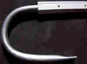
 Brackets for attaching the antenna to the wall come in different lengths; the longer the bracket extends, the greater the angle you can rotate the antenna, if necessary. There are simply situations when there is not one, but two or even three broadcasters “nearby”, and you don’t know exactly which of them will receive the signal better.
As for the height at which the antenna will be located, it must correspond to the surrounding conditions (mountain-lowland, terrain up to the translator, etc.). Here I would mostly advise you to pay attention to the installation height of the antennas that are already available in the area, i.e. on neighboring dacha plots.
I think that we are not talking about long-range reception, in its full understanding, in the case of digital television, therefore It is unlikely that you will need to strive for some exorbitant antenna mounting height. By and large, you need to try everything, despite the fact that, naturally, the higher the better.
For advanced users, to determine the required antenna mounting height, I can recommend getting acquainted with the linktest service
As an epilogue.
You can summarize everything written above about antennas for receiving terrestrial digital television in the country by compiling a list of recommendations:
- To receive over-the-air DVB-T2 television broadcasts, an antenna that operates in the UHF range is sufficient. If you already have an all-wave television antenna at your dacha, then you can use it; you are unlikely to need to purchase another additional one;
- When choosing a dacha antenna and determining its direction, the successful experience of your dacha neighbors will be very useful;
- An indoor antenna in a country house can only be used if the area is located in a zone of reliable reception within the line of sight of the translator, when the level of the DVB-T2 digital television signal indoors is sufficiently high;
- The best quality of terrestrial digital signal reception at the dacha and in a country house will be provided by an external all-wave or UHF antenna. Directional antennas of the “wave channel” type and log-periodic antennas have proven to be the most effective when receiving DVB-T2 signals. All other things being equal, it is better to choose an antenna with a higher gain and/or lower mass;
- An unambiguous answer to the question - which antenna is better, active (with a built-in amplifier) or passive? - does not exist. You just need to take into account that the amplifier serves only to compensate for losses in the cable and/or splitter for several TVs, and if the antenna design itself does not receive anything at all, then there will be nothing to amplify either. The main disadvantage of active antennas is that the built-in amplifier, in the absence of normal lightning protection and “proper” grounding, quite often “crashes”. Any cheap arresters in the absence, I emphasize, of a reliable and, most importantly, well-made grounding system are also unlikely to help;
- I believe that in the vast majority of cases, when receiving digital TV in the countryside, it is advisable to start by trying to “make do” with a passive antenna, and if necessary, you can always purchase an amplifier additionally. The cost of an active antenna with a built-in amplifier and, as an alternative, a passive antenna + an additional built-in amplifier, are practically the same. The second option is more practical, because if necessary, the mortise amplifier can be easily replaced;
- You should not strive to buy the most expensive antenna, it is absolutely not a fact that it will be better. Don’t pay attention to the tempting bullshit labels on the antenna packaging and the mind-blowing gain of tiny “nanotech” devices. As a rule, behind beautiful pictures and a set of “clever” words, there is blatant “trash”. But you shouldn’t skimp on the antenna cable; it must be of high quality;
- And lastly, if the seller of the store where you choose an antenna, instead of specific questions and advice, throws in incomprehensible terminology, and for greater importance talks about noise, about paths, about losses, about characteristics and resembles a radio amateur’s reference book, then it’s better to go to another shop.
In the article, I tried to use words that everyone can understand and, as you may have noticed, in the process of presentation I write quite often - most likely, theoretically, etc. The reason for this is that, of course, there is a lot of truth in the theory, but, firstly, we need to “drive, not checkers,” and secondly, state with 100% certainty whether any individual antenna will cope with Receiving an terrestrial digital television signal at your dacha is only possible by checking it in practice. It is enough to simply cut the cable carelessly or incorrectly, and believe me, this often happens, in order to “kill” the reception with the most wonderful antenna, and there are so many such “ifs”. For our part, in our store we collect statistics on the performance of the equipment we sell (antennas and DVB-T2 receivers) in various areas of the Leningrad region.
Despite the huge number of television antennas presented on the consumer market, which can be easily purchased at any electronics store, interest in how to make an antenna for a TV with your own hands does not disappear. This interest can be explained by a reluctance to spend money on buying an antenna, being away from retail outlets (if you are in the outback or at the dacha) or the failure of the purchased one.
Antennas for a television receiver can be divided into several types.
- All-wave antenna– the design is easy to manufacture; it can be made from simple available materials. It picks up a digital signal quite well outside the city, where there is not much interference. When located near a broadcast tower, it can receive analog television.
- Log-periodic band antenna also easy to make. It has perfect consistency with the feeder across all ranges, without changing its parameters. Since this design has average technical parameters, it can be used in the country, or as an indoor antenna in the city.
- UHF antenna. A simplified modification of the Z-antenna is often used; it works well, regardless of signal reception conditions.
All-wave antenna
All-wave TV signal catchers are also called frequency independent (FIN). Their designs can be different.
Of two petals
The figure shows an all-wave antenna made from two metal plates triangular in shape and two wooden slats on which copper wire is stretched in the shape of a fan.
Copper wire can be taken of any diameter, it does not play a special role. The ends of the wire are attached at a distance of 20 to 30 mm from each other. The plates with the other ends of the wire soldered together should be located at a distance of 10 mm from each other.
The metal plate can be replaced with a square piece of fiberglass, which has copper foil on one side.
Since the design of the homemade antenna is square, its height will be equal to its width, and the angle between the panels will be 90 degrees. Zero potential point marked in yellow in the figure. There is no need to solder the cable braid in this place - tying it tightly will be enough.
A television signal receiver assembled in this way in the form of two lobes is capable of receiving both all decimeter channels and meter ones. Moreover, it picks up signals well in all directions. But if you install the CNA in an area of poor signal reception from a TV tower, it will only work normally with amplifier. Others can also be used.
Butterfly shaped
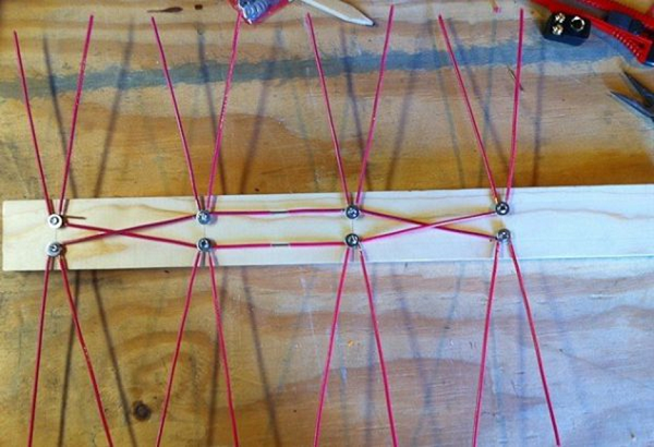
You can make a television antenna in the shape of a butterfly with your own hands. To make this fairly powerful antenna yourself, you need to prepare a board or plywood with dimensions of 550 x 70 x 5 mm, a wire with a copper core with a cross-section of 4 mm, and, accordingly, a PK75 cable.

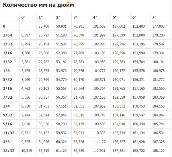
- Mark the holes on the plywood and drill them. Dimensions in the picture are in inches. Below the figure is a table for converting inches to mm.

- From copper wire you need to cut 8 pieces of the same length, 37.5 cm each.
- In the center of each wire, clear sections of insulation (2 cm each), as in the figure.

- After this, you should cut off 2 more pieces of wire, already 22 centimeters each, divide them into 3 equal parts and remove the insulation at the separation points.
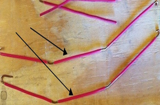
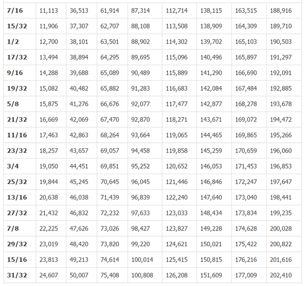
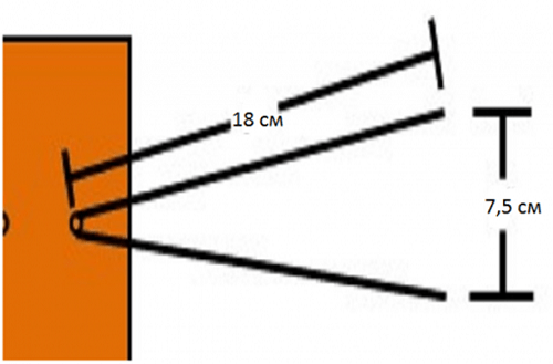
- Give the segments V-shape. You should be careful to maintain a distance of 7.5 cm between the ends of the wire. This is the optimal distance to receive a clear signal.
- Connect all the elements according to the figure below.
- Next, you need to purchase a socket to connect the plug to it.
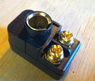
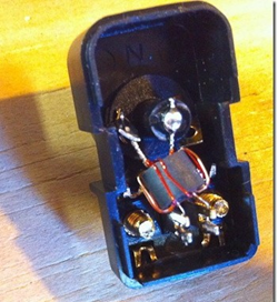
- The cable must be soldered to the coil contacts, as in the figure.

- Make 2 more pieces of wire of the required length to connect the antennae to the socket.
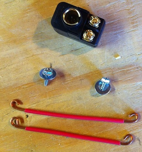
- Screw the socket onto the board and connect all the elements.

That's all - you made an antenna for your TV with your own hands.
From beer cans
To make such an original ChNA you will need 2 cans (0.5 l or 0.75) of beer or other drink. But before you make a television antenna, you need to consider some material requirements. Namely, it is recommended to purchase a high-quality television cable with a resistance of 75 ohms per meter. Which is correct? Make sure that the central core is strong and that the braid is double and continuous.
Don’t forget, the longer the cable, the stronger the signal attenuation will be, which is especially important for receiving meter waves, in contrast to UHF, for which the length of the wire also matters, but not so much.
It will also be necessary to prepare the usual wooden trempel, a couple of self-tapping screws, electrical tape or tape and, if possible, a soldering iron with tin.
An antenna made from beer cans can receive both the UHF and meter wavelengths.
To illustrate the entire process, you can watch the video.
Log-periodic antenna
A log-periodic antenna (LPA) can be used to receive radio waves in both the meter and decimeter ranges. To make such a signal receiver, you can use an aluminum tube with a diameter of 10 mm and metal rods (studs) as a stand, which can be purchased at a store that sells fasteners. Ideally, instead of threaded rods, it is better to use smooth tubes or rods. A plastic U-shaped box is used as a base.
When the soldering is completed, the manufacture of the device can be considered complete and you can begin testing your creation.
UHF antenna
Homemade decimeter signal catchers can have different shapes and designs, from the simplest to manufacture to more complex devices.
Ring-shaped
The simplest design for receiving UHF can be made in a short time with your own hands from scrap materials. All you need is a coaxial cable and a piece of plywood of the appropriate size.

Now all this needs to be assembled:
- prepare a piece of coaxial cable (RK75) 530 mm long (a ring will be made from it);
- also cut another piece of cable 175 mm long - this will be a loop;
- make a ring (1), solder a loop (2) and a cable (3) to it, which connects to the TV;
- secure it all to a plywood sheet and point the completed TV signal receiver towards the TV tower.
If your TV receiver uses such an antenna, try making a more complex device.
Figure 8
You can make your own home UHF antenna from wire in the shape of the number 8. To make such a receiver, you can use copper or aluminum wire with a diameter of 3 to 5 mm, as well as PK75 cable. During the manufacturing process you will also need glue gun
Manufacturing progress.
- Using wire cutters, you need to cut 2 pieces of wire 56 cm each.
- At the ends of each segment, make a loop, which should take 1 cm.
- Bend the wire squares and connect the loops. Solder the cable to the squares as shown in the picture. The central core is soldered to one square, and the braid to the other. The distance between the elements should be 2 cm. The entire structure can be secured in the lid of a 20 liter water bottle, filled with glue.


Such a UHF receiver can be placed anywhere, and it does not require an amplifier. Perhaps an amplifier may be needed if the device is outdoors and the cable length is significant. In this case, to compensate for signal losses, its installation will be required.
From a metal-plastic pipe
You can make a television antenna with your own hands from an ordinary metal-plastic pipe. This will result in a device for receiving UHF with a possible range from 480 MHz to 1000 MHz. This “model” uses a pipe with a diameter of 16 mm and a cable of 5.5 m. The ring will require 55 cm of pipe, and the stand will require 14 cm, which is equal to a quarter of the wavelength. This serves to better match the outer braiding of the cable and reduces high frequency currents.

The cable exit in this design is made through a hole in the pipe. The cable braid should be attached with a clamp to the stripped part of the pipe. The central core of the cable is attached to the ring (you can use a screw with a washer and a nut). This homemade product works well as an indoor antenna in apartments with reinforced concrete walls that do not transmit television waves well. Thanks to the extended cable, you can take it out onto the balcony or place it on the windowsill - the quality of reception will only improve.
In the form of a frame
Another UHF antenna design is assembled in the form of a frame. It will be made from aluminum plates(stripes).

Thus, home-made antennas will help you save money on purchasing them, and in some cases get out of the situation where you have a TV, but the standard antenna is out of order, or it doesn’t exist at all. Moreover, the quality of reception of homemade products is no worse than their factory counterparts. If you do not want to make the device yourself, then the information in the store will be useful to you.
Despite the fact that television is now taking a back seat to the Internet, many people cannot imagine their lives without it. It has long been part of our daily life. People, coming home from work or school, want to relax and watch a movie or listen to the news, rather than look for something interesting on the Internet. Of course, this is what happens in cities, but in villages there may be a weak signal, which makes it impossible to watch TV.
In this case, it is necessary to solve the problem. Usually a satellite dish is installed, which allows us to solve this qualitatively. Unfortunately, its cost and annual fee may be quite expensive for you. What can be done in this case?
Antennas
Today you can find many different antennas that will allow you to get the desired result. You can choose this device to suit any wallet. Which antenna to choose for a summer house with an amplifier?
Each antenna can receive a signal and be used as a digital one. This depends on the range of the tower and any obstacles to the signal. If the house is located close to the relay tower, then you can receive the signal even with an ordinary bare television cable.
Of course, if the area is located far enough from the tower, then it is necessary to look for alternative options. Which antenna to choose for a summer house with an amplifier? Let's look at this issue.
Types of antennas
When choosing a suitable antenna, you will see that there are quite a large number of them. They differ in the type and method of installation and reinforcement. They are all installed under different conditions. To determine which antenna is needed, it is worth deciding on the type of location and signal amplification.
Indoor antenna for a summer residence with an amplifier
Antennas that are installed indoors are quite compact and can be installed on a flat surface. This look is thus different from its outdoor alternative. Unfortunately, indoor antennas need to be installed only in the city, near it, or in cases where the cottage is located close to the tower. In other cases, you may not be able to improve your signal reception. You should also remember that in one room the signal can be quite strong, and when transferred it is lost. This happens due to walls or other obstacles.

Digital antennas for summer cottages installed outside the premises
Outdoor antennas are different from indoor ones. They are installed in houses that are located far outside the city, where conventional antennas are not able to pick up a signal. This type will improve the quality of reception. Of course, these antennas are often used, and therefore there are many types of them. They are divided by type of reinforcement and installation method. Which amplified antenna should I choose for my dacha?
The most common antennas are passive ones. They do not have additional modules that provide additional amplification. Of course, they can catch and slightly enhance the quality of reception, but usually this is not enough if the dacha is located far from the repeater tower. Even such a simple look has some positive aspects. does not introduce noise into the signal, which ensures high-quality playback, of course, if there is enough power.
The second type is active antennas. They are similar in size to the previous type, but have additional microcircuits to amplify the signal. They can be contained either in the antenna itself or separately from it in the form of an additional module. Of course, it requires power; it is installed from a regular outlet.

The last type is directional antennas, which are similar to active ones in their design. The main differences are that directional antennas are larger in size and have some additional modules. Thus, in this type, a long core is installed, and elements that provide reinforcement are connected to it. Directional antennas are perfect for remote areas; they efficiently capture and amplify the signal. You can also choose an amplifier for the TV antenna at your dacha to improve the signal.
Unfortunately, even if you choose a powerful antenna, you can get a distorted signal. Before purchasing, you need to determine the distance from the tower to the antenna and select the most suitable option.
Gain
Which antenna with amplifier to choose for your dacha? Before this, you need to understand the technical characteristics of the device. with a garden amplifier this is the gain, which is measured in dB. This indicator will show us how well a signal can be received for a certain area. Of course, the higher this indicator, the better the quality of reception and, accordingly, the higher the price. It is recommended to select an antenna with a suitable coefficient.

Selecting a cable to connect
After choosing a suitable outdoor antenna with an amplifier for your dacha, you can proceed to installation and configuration.
In order not to disturb the whole picture, it is necessary to purchase a good cable, since it also complements the quality of signal transmission. Even if you purchased an expensive receiver and antenna, a low-quality cable can ruin everything. Of course, it will match the high price. You should also take into account the thickness of the central core, which should be quite thick, and the outer braid. Before connecting, it is worth checking the characteristic impedance, which should be about 75 Ohms.

Rating of the best models
Which antenna with amplifier to choose for your dacha? It is quite difficult to advise something, since each person will have different conditions for receiving the signal. Different terrain and distance from the repeater tower determine the appropriate antenna. The rating of the best models will help you choose the appropriate option.

There is also the option of making a television antenna yourself. This way you can make a suitable option for your area. Of course, you need to work hard for this, since the task is quite difficult. There are many recommendations and videos on the Internet that will help you make a suitable TV antenna for your dacha with an amplifier.
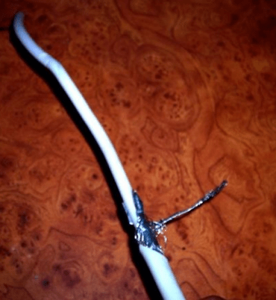
If your coaxial cable, which is connected to the antenna and TV, is broken or has been chewed by pets, do not immediately run for a new one. You can connect entire sections. To do this, you need to clean the ends and solder the necessary contacts.
To receive a high-quality signal, you need to pay attention to various factors. The height of the installation, high-voltage lines that are close to the house, the type of topography in your area, and the material used to make the roof can improve or degrade the signal. This should be used during installation so as not to waste your time.
Conclusion
TV antennas with an amplifier for a summer residence must be selected based on your area. You cannot choose a universal option; you must evaluate all the characteristics yourself to get a high-quality signal. There are several types of antennas that may be suitable for you. After determining the desired type, you can proceed to selecting the appropriate model.