DIY Wi-Fi antenna - step-by-step instructions. Homemade Wi-Fi antenna
A few months ago, my work colleagues and I were faced with the task of connecting an access point from a remote house and a car at work with a mesh so that it would work well and packages would not be lost. Following the old saying “Screw copper!”, it was decided to connect with air. Why did we buy a fairly cheap WiFi card? But bad luck, the house is not right next to each other, although not a kilometer away, but still not nearby, but in direct visibility, about 150 meters. Of course there was a connection, but still the percentage was small. We went online to the website of a local store, looked at the prices for antennas... then a toad came :) With the words, “Well, screw it, I can do it myself,” I started a long, but entertaining and exciting job :)
I scoured the Internet for antenna diagrams, while learning and remembering the basics of physics, wavelength, polarization, etc. A pair of antennas were made from scrap materials, which turned out to be blanks. But as time passed, they ceased to satisfy us, so I will not delve into the manufacture of these antennas.
It was decided to do something like an adult and make a wave channel, or rather two at once, so that it would blow from both sides.
We found a diagram, thought about the material, and didn’t find anything better than using polymer pipes :) Here is a short photo report with comments.
1) A diagram of a 16-element wave channel was found.
2) I bought a pipe, cut it

3) I cut the elements. It was important to do it exactly with the circuit, because we would not have measured the wavelength on our own.
I brought a bar from home, cut the elements, then stubbornly ground off the extra millimeters and tenths of them

4) Measured and made holes in the tubes

Then, painstakingly and not without effort, I inserted each element into the holes, aligned
Next, a 50 Ohm coaxial cable and connectors were purchased (the most expensive of the entire craft). Then everything was crimped and the antenna was ready :)

(after the photo was taken, the cable was shortened by half to avoid losses)
By the way, yes! Two wave channels were made in one working day, and it was Radio Day!
z.y. The percentages have doubled, we don’t lose packets, we have a stable connection...
before the antenna was ready the speed was 24 Mbit, after 48 Mbit
UPD: wave channel diagram with dimensions
UPD2:
materials that were involved:
Polypropylene pipe
- copper wire
- 50 Ohm coaxial cable
- SMA connectors
WiFi antenna- an excellent solution for anyone who has tried to organize wireless Internet distribution at home or at work, but has encountered the problem that the router signal is not enough to use it without problems in some remote room. However, this is not the fault of your router, but of the antenna - built-in or external, which was included in the package. One of the most effective solutions for strengthening a wireless signal is directional external wifi antenna They come in several types and types that are used depending on your needs. And it is precisely this diversity that we will now understand.
First of all, it should be noted that a passive antenna for a wifi router, that is, which does not have its own power supply from the mains, does not amplify the signal, but only directs its spectrum for more reliable reception. The power of this “amplification,” also called directional gain, is measured in decibels (dBi). Many models of routers and adapters are already equipped with small external antennas, but their power does not exceed 3-5 dBi, which will not significantly improve the range of the wireless signal.
Therefore, external wifi antennas are used for this. They have two types of separation - for outdoor or indoor use, as well as omnidirectional and narrow directional.
Outdoor and indoor antenna use
- Outdoor antennas are those that are designed to work outdoors. They are protected from the effects of precipitation and sunlight and have special fastenings for installation on the wall of a building. They will be needed if you want to create a secure reception area in the yard or for communication between neighboring houses.
- Indoor antennas - for indoor use. For example, if your router is installed in a remote or closed place, then such an antenna can be connected with a cable to the antenna connector of the router and brought to the center of the room.
Directional wifi antenna
This is the most used type. An antenna that directs a wifi signal in a certain direction, for example, from a house to a personal plot, or to the balcony of a neighboring house, if we are talking about an external directional wireless antenna. Their range of action can be from one to several km. The main thing is that the reception source is in direct line of sight.

Internal directional wifi antennas for a router will be useful if, for example, it hangs on the wall. To prevent radiation from reaching the wall, you can connect it to the router and point it towards your desktop on which the laptop is placed. Or vice versa, point the antenna at the partition so that the signal passes through it more confidently, providing stable communication in the next room. A very successful design of such an antenna is a panel rectangle that emits a radio signal in one direction.

Please note that it is connected to the router not via USB, but instead of the attached antenna that came with the router. Accordingly, if it was not removable, then it will not be possible to replace it with another one.
There are also compact models that are suitable for both indoor use and outdoor mounting.

An omnidirectional wifi antenna is distinguished by the fact that it evenly distributes the signal around itself. The disadvantage is that the signal may be distorted by emissions from other electronic devices located in the apartment, or by external radio waves if it is installed outdoors. These antennas look like a vertical rod. External ones can be installed on the roof of the house or on a vertical pole dug into the ground. Internal - on a table or shelf, as close as possible to the expected center of the desired reception area.

The external wifi antenna for the router is attached in the same way in place of the standard one to the same connector.

Another interesting type of indoor omnidirectional wifi antennas is for ceiling mounting. They look like a lamp. Its peculiarity is that there is a dead zone directly under the antenna and it needs to be hung exactly in the place where the signal is not needed, and reliable reception will begin only at a short distance from it.
Installing a WiFi antenna
When installing any type of antenna, it is necessary to consider where the signal source is coming from. In modern urban development, it can greatly lose efficiency both due to the density of houses and the materials from which they are made. I provide a table from which you can roughly understand how much this or that material degrades the performance of the access point. The most important parameter here will be “Effective distance” (ED). It must be calculated as follows. For example, the characteristics of the router indicate that it operates at 400 meters. it is understood that with direct visibility. You are separated from it by an interior wall with an ER of 15%. We calculate: 400 m multiplied by 15% and we get 60 meters. That is, through a 15-20 cm wall, the router will “shoot” only 60 meters. Moreover, if you attach an antenna of 15-20 decibels to it, then this loss will be neutralized.
Homemade wifi antenna with your own hands
You can make a directional Wi-Fi antenna with your own hands. Watch a video on how to make a homemade structure from an ordinary beer can.
I can’t say for sure whether this is true or false - I think there is some reason. By analogy with this popular example, you can also make a directional antenna from an omnidirectional one. To do this, it is enough to attach a reflective screen behind it, for example, from the same sheet of foil. Below are several interesting options for making an antenna with your own hands that you can use.
 Option with a tin can as a reflector


That's all for today. You can read about ways to strengthen the signal of a 3G modem in another article on the blog.
Instructions for making a “double” Bi-Quad (double eight) W-LAN antenna - 2.4 Ghz antennas for wi-fi.
"Double Eight" is a continuation of Bi-Quad, the gain of which is 2 dB higher, i.e. is approximately 12 dB. During construction, pay attention to the fact that the copper wires do not touch at the intersection points. After construction, it is advisable to varnish the “double eight” to avoid oxidation/corrosion. The two photographs below demonstrate how important it is to maintain a distance of 15 mm between the reflector and the copper wire:


In order to avoid questions (there were in the first post), let's consider building an antenna with a circular diagram, in this case something around 270°.

First, from a copper plate (or other sheet metal/material), you need to bend a pipe with a diameter of 70 mm and a height of approx. 100 mm. Then bend a straight 6-element Quad from copper wire and, using, for example, a bottle, give it a corresponding, curved shape. I repeat for those who are not reading very carefully: the distance from the copper wire to the reflector in a circle should be 15 mm! It is important that the crossing wires do not touch each other!

Of course, this is not the only correct option for building such an antenna. The antenna with a pie chart can be made larger,


In this case, signal loss in the antenna cable will be minimized.


Ideally it should look a little different, something like this:

but this is not so important, the main thing is that you can repeat the dimensions by printing. For those bending the “double eight” - the outer squares are not used. Those who do not have a printer can use the following drawing to make a frame: the dimensions are for a wire with a diameter of 2.5 mm

"Triple Eight" is another continuation of the "double eight", the gain coefficient of the "triple eight" can be 14 dB or a little more. This is what a colored “triple eight” looks like, in general, not bad:


For beginners! Please note that the stands supporting the antenna at a distance of 15 mm from the reflector must be made of dielectric material!
The “double eight” and the antenna with a pie diagram discussed above can be mounted together in one housing:


From another.

The antenna is closed. To make the protective housing, a piece of plastic pipe with a diameter of 125 mm, which is used in plumbing, was used; the lid is made of 2-centimeter plastic. The top fastening nut is made of plastic. Can be painted any color.


If you want to assemble a long-range WiFi antenna, then you should know about some of its features.
The first and simplest: large antennas of 15 or 20 dBi (isotropic decibels) are the maximum power, and there is no need to make them even more powerful.
Here is a clear illustration of how, as the antenna power in dBi increases, its coverage area decreases.
It turns out that as the antenna’s operating distance increases, its coverage area decreases significantly. At home, you will have to constantly catch a narrow band of signal coverage if the WiFi emitter is too powerful. Get up from the couch or lie down on the floor, and the connection will immediately disappear.
That's why home routers have conventional 2 dBi antennas that radiate in all directions - so they are most effective over short distances.
Directed
9 dBi antennas only work in a given direction (directional) - they are useless in a room, they are better used for long-distance communications, in the yard, in the garage next to the house. The directional antenna will need to be adjusted during installation to transmit a clear signal in the desired direction.
Now to the question of carrier frequency. Which antenna will work better at long range, 2.4 or 5 GHz?
Now there are new routers operating at double the frequency of 5 GHz. These routers are still new and are good for high-speed data transfer. But the 5 GHz signal is not very good for long distances, as it fades faster than 2.4 GHz.
Therefore, old 2.4 GHz routers will work better in long-range mode than new high-speed 5 GHz ones.
Drawing of a double homemade biquadrat
The first examples of homemade WiFi signal distributors appeared back in 2005.
The best of them are the biquadrate designs, which provide a gain of up to 11–12 dBi, and the double biquadrate, which has a slightly better result of 14 dBi.
According to usage experience, the biquadrate design is more suitable as a multifunctional emitter. Indeed, the advantage of this antenna is that with the inevitable compression of the radiation field, the signal opening angle remains wide enough to cover the entire area of the apartment when installed correctly.
All possible versions of a biquad antenna are easy to implement. 
Required Parts
- Metal reflector - a piece of foil-textolite 123x123 mm, a sheet of foil, a CD, a DVD CD, an aluminum lid from a tea can.
- Copper wire with a cross section of 2.5 mm2.
- A piece of coaxial cable, preferably with a characteristic impedance of 50 Ohms.
- Plastic tubes - can be cut from a ballpoint pen, felt-tip pen, marker.
- A little hot glue.
- N-type connector - useful for conveniently connecting an antenna.
For the 2.4 GHz frequency at which the transmitter is planned to be used, the ideal biquadrate size would be 30.5 mm. But still, we are not making a satellite dish, so some deviations in the size of the active element - 30–31 mm - are acceptable.
The issue of wire thickness also needs to be considered carefully. Taking into account the selected frequency of 2.4 GHz, a copper core must be found with a thickness of exactly 1.8 mm (section 2.5 mm2).
From the edge of the wire we measure a distance of 29 mm to the bend.
We make the next bend, checking the outer size of 30–31 mm.
We make the next inward bends at a distance of 29 mm.
We check the most important parameter of the finished biquadrat -31 mm along the center line.
We solder the places for future fastening of the coaxial cable leads.
Reflector
The main task of the iron screen behind the emitter is to reflect electromagnetic waves. Correctly reflected waves will superimpose their amplitudes on the vibrations just released by the active element. The resulting amplifying interference will make it possible to propagate electromagnetic waves as far as possible from the antenna.
To achieve useful interference, the emitter must be positioned at a distance that is a multiple of a quarter of the wavelength from the reflector.
Distance from emitter to reflector for biquad and double biquad antennas we find lambda / 10 - determined by the features of this design / 4.
Lambda is a wavelength equal to the speed of light in m/s divided by the frequency in Hz.
Wavelength at a frequency of 2.4 GHz is 0.125 m.
Increasing the calculated value five times, we get optimal distance - 15.625 mm.
Reflector size affects the antenna gain in dBi. The optimal screen size for a biquad is 123x123 mm or more, only in this case can a gain of 12 dBi be achieved.
The sizes of CDs and DVDs are clearly not enough for complete reflection, so biquad antennas built on them have a gain of only 8 dBi.
Below is an example of using a tea jar lid as a reflector. The size of such a screen is also not enough, the antenna gain is less than expected.
Reflector shape should only be flat. Also try to find plates that are as smooth as possible. Bends and scratches on the screen lead to the dispersion of high-frequency waves due to disruption of reflection in a given direction.
In the example discussed above, the sides on the lid are clearly unnecessary - they reduce the signal opening angle and create scattered interference.
Once the reflector plate is ready, you have two ways to assemble the emitter on it.
- Install the copper tube using soldering.
To fix the double biquadrat, it was necessary to additionally make two stands from a ballpoint pen.
- Secure everything to the plastic tube using hot glue.
We take a plastic box for discs for 25 pieces.
Cut off the central pin, leaving a height of 18 mm.
Use a file or file to cut four slots in the plastic pin.
We align the slots to the same depth
We install the homemade frame on the spindle, check that its edges are at the same height from the bottom of the box - about 16 mm.
Solder the cable leads to the emitter frame.
Taking a glue gun, we attach the CD to the bottom of the plastic box.
We continue to work with a glue gun and fix the emitter frame on the spindle.
We fix the cable on the back of the box with hot glue.
Connecting to a router
Those who have experience can easily solder to the contact pads on the circuit board inside the router.
Otherwise, be careful, thin traces may come off the printed circuit board when heated for a long time with a soldering iron.
You can connect to an already soldered piece of cable from a native antenna via an SMA connector. You shouldn't have any problems purchasing any other N-type RF connector from your local electronics store.
Antenna tests
Tests have shown that an ideal biquad gives a gain of about 11–12 dBi, and this is up to 4 km of directional signal.
The CD antenna gives 8 dBi, since it can pick up a WiFi signal at a distance of 2 km.
Double biquadrate provides 14 dBi - slightly more than 6 km.
The opening angle of antennas with a square emitter is about 60 degrees, which is quite enough for the yard of a private house.
About the range of Wi-Fi antennas
From a native router antenna of 2 dBi, a 2.4 GHz signal of the 802.11n standard can spread over 400 meters within line of sight. Signals of 2.4 GHz, old standards 802.11b, 802.11g, travel worse, having half the range compared to 802.11n.
Considering a WiFi antenna to be an isotropic emitter - an ideal source that distributes electromagnetic energy evenly in all directions, you can be guided by the logarithmic formula for converting dBi to power gain.
Isotropic decibel (dBi) is the antenna gain, determined as the ratio of the amplified electromagnetic signal to its original value multiplied by ten.
AdBi = 10lg(A1/A0)
Conversion of dBi antennas into power gain.
| A,dBi | 30 | 20 | 18 | 16 | 15 | 14 | 13 | 12 | 10 | 9 | 6 | 5 | 3 | 2 | 1 |
| A1/A0 | 1000 | 100 | ≈64 | ≈40 | ≈32 | ≈25 | ≈20 | ≈16 | 10 | ≈8 | ≈4 | ≈3.2 | ≈2 | ≈1.6 | ≈1.26 |
Judging by the table, it is easy to conclude that a directional WiFi transmitter with a maximum permissible power of 20 dBi can distribute a signal over a distance of 25 km in the absence of obstacles.
A weak WiFi signal is a pressing problem for residents of apartments, country houses and office workers. Dead zones in a WiFi network are typical for both large rooms and small apartments, the area of which even a budget access point can theoretically cover.
The range of a WiFi router is a characteristic that manufacturers cannot clearly indicate on the box: the WiFi range is influenced by many factors that depend not only on the technical specifications of the device.
This material presents 10 practical tips that will help eliminate the physical causes of poor coverage and optimize the range of your WiFi router; you can easily do it yourself.
The radiation from the access point in space is not a sphere, but a toroidal field, shaped like a donut. In order for WiFi coverage within one floor to be optimal, radio waves must propagate in a horizontal plane - parallel to the floor. For this purpose, it is possible to tilt the antennas.

The antenna is a donut axis. The angle of signal propagation depends on its inclination.

When the antenna is tilted relative to the horizon, part of the radiation is directed outside the room: dead zones are formed under the “donut” plane.

A vertically mounted antenna radiates in a horizontal plane: maximum coverage is achieved indoors.
In practice: Mounting the antenna vertically is the easiest way to optimize indoor WiFi coverage.
Place the router closer to the center of the room
Another reason for the occurrence of dead zones is the poor location of the access point. The antenna emits radio waves in all directions. In this case, the radiation intensity is maximum near the router and decreases as it approaches the edge of the coverage area. If you install an access point in the center of the house, the signal will be distributed throughout the rooms more efficiently.
A router installed in a corner transmits some of the power outside the house, and distant rooms are at the edge of the coverage area.
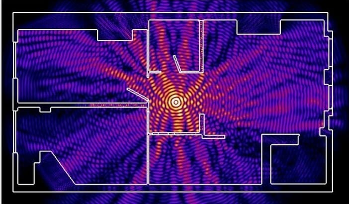
Installation in the center of the house allows you to achieve even distribution of the signal in all rooms and minimize dead zones.
In practice: Installing an access point in the “center” of the house is not always feasible due to the complex layout, lack of sockets in the right place, or the need to lay a cable.
Provide direct visibility between the router and clients
WiFi signal frequency is 2.4 GHz. These are decimeter radio waves that do not bend well around obstacles and have low penetrating ability. Therefore, the range and signal stability directly depend on the number and structure of obstacles between the access point and clients.

Passing through a wall or ceiling, an electromagnetic wave loses some of its energy.
The amount of signal attenuation depends on the material the radio waves travel through.
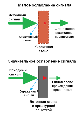

*Effective distance is a value that determines how the radius of a wireless network changes in comparison with open space when a wave passes an obstacle.
Calculation example: WiFi 802.11n signal propagates under line-of-sight conditions over 400 meters. After overcoming the non-permanent wall between the rooms, the signal strength decreases to 400 m * 15% = 60 m. The second wall of the same type will make the signal even weaker: 60 m * 15% = 9 m. The third wall makes signal reception almost impossible: 9 m * 15 % = 1.35 m.
Such calculations will help calculate dead zones that arise due to the absorption of radio waves by walls.
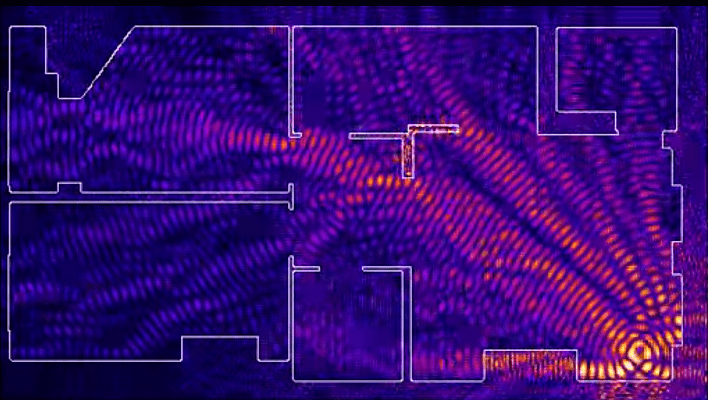
The next problem in the path of radio waves: mirrors and metal structures. Unlike walls, they do not weaken, but reflect the signal, scattering it in arbitrary directions.
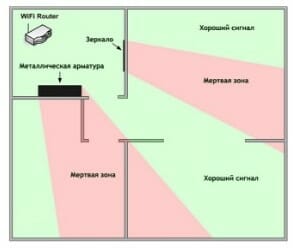
Mirrors and metal structures reflect and scatter the signal, creating dead zones behind them.

If you move interior elements that reflect the signal, you can eliminate dead spots.
In practice: It is extremely rare to achieve ideal conditions when all gadgets are in direct line of sight to the router. Therefore, in a real home, you will have to work separately to eliminate each dead zone:
- find out what interferes with the signal (absorption or reflection);
- think about where to move the router (or piece of furniture).
Place the router away from sources of interference
The 2.4 GHz band does not require licensing and is therefore used for the operation of household radio standards: WiFi and Bluetooth. Despite the low bandwidth, Bluetooth can still interfere with the router.
Green areas - stream from the WiFi router. Red dots are Bluetooth data. The proximity of two radio standards in the same range causes interference, reducing the range of the wireless network.
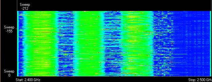
The magnetron of a microwave oven emits in the same frequency range. The radiation intensity of this device is so high that even through the protective screen of the furnace, the magnetron radiation can “illuminate” the radio beam of the WiFi router.
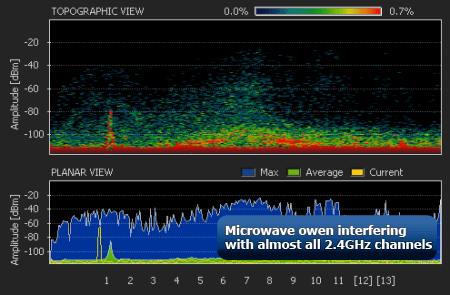
Microwave oven magnetron radiation causes interference on almost all WiFi channels.
In practice:
- When using Bluetooth accessories near the router, enable the AFH parameter in the settings of the latter.
- The microwave is a powerful source of interference, but it is not used very often. Therefore, if it is not possible to move the router, then you simply won’t be able to make a Skype call while preparing breakfast.
Disable support for 802.11 B/G modes
WiFi devices of three specifications operate in the 2.4 GHz band: 802.11 b/g/n. N is the newest standard and provides greater speed and range compared to B and G.

The 802.11n (2.4 GHz) specification provides greater range than legacy B and G standards.
802.11n routers support previous WiFi standards, but the mechanics of backward compatibility are such that when a B/G device appears in the N-router's coverage area - for example, an old phone or a neighbor's router - the entire network is switched to B/G mode. Physically, the modulation algorithm changes, which leads to a drop in the speed and range of the router.
In practice: Switching the router to “pure 802.11n” mode will definitely have a positive effect on the quality of coverage and throughput of the wireless network.
However, B/G devices will not be able to connect via WiFi. If it is a laptop or TV, they can be easily connected to the router via Ethernet.
Select the optimal WiFi channel in the settings
Almost every apartment today has a WiFi router, so the density of networks in the city is very high. Signals from neighboring access points overlap each other, draining energy from the radio path and greatly reducing its efficiency.

Neighboring networks operating at the same frequency create mutual interference, like ripples on the water.
Wireless networks operate within a range on different channels. There are 13 such channels (in Russia) and the router switches between them automatically.
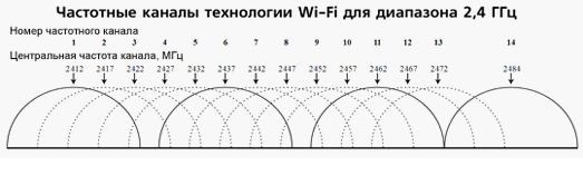
To minimize interference, you need to understand which channels neighboring networks operate on and switch to a less loaded one.
Detailed instructions for setting up the channel are provided.

In practice: Selecting the least loaded channel is an effective way to expand the coverage area, relevant for residents of an apartment building.
But in some cases there are so many networks on the air that not a single channel provides a noticeable increase in WiFi speed and range. Then it makes sense to turn to method No. 2 and place the router away from the walls bordering neighboring apartments. If this does not bring results, then you should think about switching to the 5 GHz band (method No. 10).
Adjust the router transmitter power
The power of the transmitter determines the energy of the radio path and directly affects the range of the access point: the more powerful the beam, the further it hits. But this principle is useless in the case of omnidirectional antennas of household routers: in wireless transmission, two-way data exchange occurs and not only clients must “hear” the router, but also vice versa.
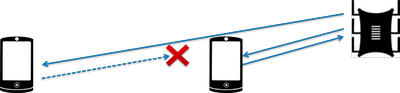
Asymmetry: the router “reaches” a mobile device in a distant room, but does not receive a response from it due to the low power of the smartphone’s WiFi module. The connection is not established.
In practice: The recommended transmitter power value is 75%. It should be increased only in extreme cases: turning the power up to 100% not only does not improve the quality of the signal in distant rooms, but even worsens the stability of reception near the router, since its powerful radio stream “clogs” the weak response signal from the smartphone.
Replace the standard antenna with a more powerful one
Most routers are equipped with standard antennas with a gain of 2 - 3 dBi. The antenna is a passive element of the radio system and is not capable of increasing the flow power. However, increasing the gain allows you to refocus the radio signal by changing the radiation pattern.

The higher the antenna gain, the further the radio signal travels. In this case, the narrower flow becomes similar not to a “donut”, but to a flat disk.

There is a large selection of antennas for routers with a universal SMA connector on the market.


In practice: Using an antenna with high gain is an effective way to expand the coverage area, because simultaneously with the signal amplification, the sensitivity of the antenna increases, which means the router begins to “hear” remote devices. But due to the narrowing of the radio beam from the antenna, dead zones appear near the floor and ceiling.
Use signal repeaters
In rooms with complex layouts and multi-story buildings, it is effective to use repeaters - devices that repeat the signal from the main router.


The simplest solution is to use an old router as a repeater. The disadvantage of this scheme is that the throughput of the child network is half as much, since along with client data, the WDS access point aggregates the upstream flow from the upstream router.
Detailed instructions for setting up a WDS bridge are provided.
Specialized repeaters do not have the problem of reducing bandwidth and are equipped with additional functionality. For example, some Asus repeater models support the roaming function.

In practice: No matter how complex the layout, repeaters will help you deploy a WiFi network. But any repeater is a source of interference interference. When there is free air, repeaters do their job well, but with a high density of neighboring networks, the use of repeater equipment in the 2.4 GHz band is impractical.
Use 5 GHz band
Budget WiFi devices operate on the 2.4 GHz frequency, so the 5 GHz band is relatively free and has little interference.

5 GHz is a promising range. Works with gigabit streams and has increased capacity compared to 2.4 GHz.
In practice: “Moving” to a new frequency is a radical option, requiring the purchase of an expensive dual-band router and imposing restrictions on client devices: only the latest models of gadgets work in the 5 GHz band.
The problem with WiFi signal quality is not always related to the actual range of the access point, and its solution broadly comes down to two scenarios:
- In a country house, most often it is necessary to cover an area in free air conditions that exceeds the effective range of the router.
- For a city apartment, the range of a router is usually sufficient, but the main difficulty is eliminating dead zones and interference.
The methods presented in this material will help you identify the causes of poor reception and optimize your wireless network without resorting to replacing the router or the services of paid specialists.
Found a typo? Select the text and press Ctrl + Enter