Inductive reactance is determined by the formula. Inductive reactance in an AC circuit
We know that the self-induction current of the coil meets the increasing current of the generator. This is it the opposition of the self-induction current of the coil to the increasing current of the generator is called inductive reactance.
Part of the energy is spent on overcoming this opposition AC generator All this part of the energy is completely converted into energy magnetic field coils. When the generator current decreases, the magnetic field of the coil will also decrease, cutting off the coil and inducing a self-induction current in the circuit. Now the self-induction current will flow in the same direction as the decreasing generator current.
Thus, all the energy expended by the generator current to overcome the counteraction of the self-induction current of the coil is completely returned to the circuit in the form of energy electric current. Therefore, inductive reactance is reactive, i.e., it does not cause irreversible energy losses.
The unit of inductive reactance is Ohm
Inductive reactance is denoted by X L.
The letter X- means reactance, and L means that this reactance is inductive.
f - frequency Hz, L - coil inductance H, X L - inductive reactance Ohm
Relationship between phases U and I on X L

Since the active resistance of the coil is equal to zero (purely inductive resistance), then all the voltage applied by the generator to the coil is used to overcome the e. d.s. self-inductance of the coil. This means that the graph of the voltage applied by the generator to the coil is equal in amplitude to the graph of e. d.s. self-induction of the coil and is in antiphase with it.
The voltage applied by the generator to the purely inductive reactance and the current flowing from the generator through the purely inductive reactance are shifted in phase by 90 0, i.e. that is, the voltage leads the current by 90 0.
In addition to inductive reactance, a real coil also has active resistance. These resistances should be considered connected in series.
At the active resistance of the coil, the voltage applied by the generator and the current coming from the generator are in phase.
On a purely inductive reactance, the voltage applied by the generator and the current coming from the generator are shifted in phase by 90 0. Voltage leads current by 90 0. The resulting voltage applied by the generator to the coil is determined by the parallelogram rule.

click on the picture to enlarge
The resulting voltage applied by the generator to the coil always leads the current by an angle less than 90 0.
The magnitude of the angle φ depends on the values of the active and inductive resistance of the coil.
About the resulting coil resistance
The resulting resistance of the coil cannot be found by summing the values of its active and reactive resistances.
The resulting coil resistance Z is

Inductive reactance
Let's apply an alternating voltage to the coil, neglecting active resistance (the coil is made of large-section wire).
A current will flow through the coil that is less than with direct current due to the influence of self-induction emf.
At time t, current flows in the circuit
i = I m sin ωt, and after a very short period of time ∆t the current will be equal to
i + ∆i = I m (sin ω (t + ∆t),
This means that during this time the current will change by the amount
∆i = I m (sin ω (t + ∆t) - sin ωt)
Sine of the sum sin ω (t + ∆t) = sin ωt cos ω ∆t + cos ωt sin ω ∆t
The cosine of a very small angle ω ∆t is approximately equal to 1, and the sine of this angle is equal to the corresponding arc sin ω ∆t = ω ∆t. Therefore we get
∆i = I m (sin ω t + ω ∆t cos ωt - sin ωt) = I m ω ∆t cos ωt.
The rate of change of sinusoidal current ∆i/∆t = I m ω cos ωt, then
u = e L = L I m ω cos ωt = I m ω L sin (ωt + 90 0).
Voltage is measured in V, current is in A, then ω L is measured in Ohms and is called inductive reactance
Inductive reactance increases with increasing current frequency.
A self-inductive emf will be induced in the coil from a change in its own magnetic flux. This emf balances the applied voltage. According to Kirchhoff's second law, at any time u+e=0
Hence for instantaneous values u = - e. At any moment of time, the voltage applied to the coil is balanced by the EMF induced in it.
From here
Let's find the derivative of the current
 .
.
Then ![]()
Using reduction formulas we get
On the coil, the voltage leads the current by 90 0 or the current lags the voltage by 90 0. It is easy to see that the dimensions of the left and right parts must coincide so that Lω had the dimension V/A, and this is Ohm and is designated X L
X L = ω L- inductive reactance. Inductive reactance depends on the frequency of the current and on the inductance. As frequency increases, inductive reactance increases.
The lag of the current varying along a sine wave from the voltage varying along a cosine wave is clearly visible from the graphs (Fig. 1.3).

Figure 1.3 - Current and voltage sinusoids
Depicting alternating current and alternating voltage using sinusoids is cumbersome. Therefore, we replace the sinusoid with a vector. To do this, let us depict a sinusoid as a function of the angle of rotation of the generator rotor α = ωt. (Fig. 1.4). All turbogenerators of Russian power plants rotate at the same frequency of 50 rps, which corresponds to 50 periods of change in the voltage sinusoid.

Figure 1.4 - Replacing a sinusoid with a vector
When ωt= 0, we will place the vector equal to the amplitude of the sinusoid horizontally, directed to the right. We will determine the instantaneous voltage values at any moment of time by projecting the vector onto the vertical axis (vector ordinate). Then the instantaneous value after 45 0 of the sinusoidal value will be equal to ab. But when the vector is rotated by 45 0, the instantaneous value (ordinate) is also equal to ab. When the vector is rotated by 90 0, the instantaneous value is equal to the amplitude, the same is reflected in the sinusoid. This means that any sinusoidal quantity can be replaced by a rotating vector with frequency ω counterclockwise.
The period of time required for the variable EMF to complete a full cycle (circle) of its changes is called the period of oscillation or abbreviated period .
Dimension of angular frequency ω =360 0 /T, where T =1/f- the period of oscillation or the complete cycle of change in the instantaneous values of current, voltage and any sinusoidal value.
The angular frequency is expressed in radians, 1 radian = 57 0 17’, then the circle is 360 0 = 2π rad ≈ 6.28 rad..
ω = 2 π f; ω= 2 ∙3.14∙ 50 = 314 rad/s = 314 1/s - this is the synchronous rotation speed of the generator rotor and the magnetic field created by the rotor. With this frequency the instantaneous value of the sinusoid of current or voltage in the network changes
The relationship between sinusoidal different electrical quantities and their relative position on the plane, expressed graphically in the form of vectors, is called vector diagram.
Let's consider a chain in which an active resistance and an inductor are connected to a voltage source U.

Figure 1.5 - Connection to a source of active and inductive resistance
Let's direct the current vector horizontally. The voltage drop vector across the active resistance will be located in the same direction U R. In inductance, the current lags behind the voltage U L at 90 0. Source voltage U IST is obtained as a result of vector addition U R and U L
U = U R+ U L.

Figure 1.6 - Voltage vectors on active and inductive resistances
The resulting diagram shows that in the considered circuit with an inductor, the current lags behind the source voltage by an angle φ.
In a vector diagram if
U R= I R , That U L= I X L,
The inductance of a coil in the air is a constant value and is determined by the design (number of turns, dimensions of the coil). And the inductive reactance depends on the frequency of the current and is found by the expression
![]() .
.
Angle φ (see Fig. 1.6) depends on the ratio of inductive and active resistance.
 .
.
In addition to the inductive reactance in electrical circuits Another reactive - capacitive reactance should be taken into account, the value of which depends on the frequency and size of the capacitance
 .
.
As the frequency increases, the capacitor's capacitance to alternating current decreases. Unlike inductance, the current in a capacitor leads the voltage. The capacitor plates are recharged every half cycle of the alternating voltage.
But, if connected to the capacitor constant voltage, (from the battery), then after charging, no current flows through the capacitor.
The ratio of resistance and power on alternating current
On alternating current, it is necessary to take into account not only the active resistance of the conductors, but also the reactive one (capacitive or, more often, inductive). From the vector diagram of voltages on active and inductive resistances (see Fig. 1.6) it is clear that the vectors U R and U L are located at 90 0 relative to each other, and the three vectors U R, U L and U IST form a right triangle.
The angle φ shows how much the current in resistance Z lags behind the voltage. The quantity cos φ is called power factor. We divide the lengths of the segments of this triangle by the current I, we obtain the resistances R, X L and Z, which also represent the sides of a right triangle, from which we obtain
![]() ,
,
where Z is the total resistance of the network section to alternating current.

Figure 1.7 - Resistance triangle
If the active resistance and angle φ are known, then Z = R/cos φ. Any network element through which alternating current flows has a given resistance ratio. In complex form, the resistance ratio is written
Z = R + jX.
The active resistance on alternating current is almost the same as the resistance on direct current, so it can be measured with an ohmmeter. And the impedance to alternating current is calculated using Ohm's law through the measured voltage and current, and then calculate
Z = U PER /I PER.
The alternating current in a circuit with inductance lags behind the applied voltage (see Fig. 1.6)). Let's build a vector voltage diagram U and current I. For convenience, let us rotate the voltage vector diagram so that the voltage vector is located vertically. After this, we decompose the current vector into the active component I A and the reactive component I P, we obtain a triangle of currents (Fig. 1.8).

Figure 1.8 - Decomposition of current into components
There is an angle φ between the active component and the total current in the section. Let us multiply each side of the triangle of currents by voltage U, then the sides will be
Where S- full power; R - active power; Q- reactive power.

Figure 1.9 - Power ratio
From the power triangle we conclude that the power factor cos φ = P/S shows what proportion of full power is the active power. At any part of the network the ratio is observed
), we assumed the active resistance of this circuit to be zero.
However, in reality, both the wire of the coil itself and the connecting wires have, although small, active resistance, so the circuit inevitably consumes the energy of the current source.
Therefore, when determining the total resistance of an external circuit, you need to add its reactive and active resistance. But it is impossible to add these two resistances, which are different in nature.
In this case, the total resistance of the circuit to alternating current is found by geometric addition.
A right triangle is constructed (see Figure 1), one side of which is the value of inductive reactance, and the other side is the value active resistance. The required total resistance of the circuit is determined by the third side of the triangle.
Figure 1. Determination of the impedance of a circuit containing inductive and active resistance
The impedance of the circuit is indicated by Latin letter Z and is measured in ohms. From the construction it is clear that the total resistance is always greater than the inductive and active resistances taken separately.
The algebraic expression for the total resistance of the circuit is:
![]()
Where Z - total resistance, R - active resistance, XL - inductive resistance of the circuit.
Thus, The total resistance of an alternating current circuit, consisting of active and inductive resistance, is equal to the square root of the sum of the squares of the active and inductive resistance of this circuit.
For such a circuit it will be expressed by the formula I = U / Z, where Z is the total resistance of the circuit.
Let us now analyze what the voltage will be if the circuit, in addition to and and the phase shift between the current and the inductance, also has a relatively large active resistance. In practice, such a circuit can be, for example, a circuit containing an inductor without an iron core, wound from a thin wire (high frequency choke).
In this case, the phase shift between current and voltage will no longer be a quarter of a period (as was the case in a circuit with only inductive reactance), but much less; Moreover, the greater the active resistance, the smaller the phase shift will be.
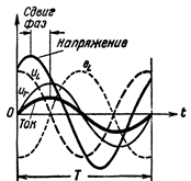
Figure 2. Current and voltage in a circuit containing R and L
Now it itself is not in antiphase with the voltage of the current source, since it is no longer shifted relative to the voltage by half a period, but less. In addition, the voltage created by the current source at the coil terminals is not equal to the self-inductive emf, but is greater than it by the amount of voltage drop in the active resistance of the coil wire. In other words, the voltage on the coil consists of two components:
u L - reactive component of the voltage, balancing the action of the self-inductive emf,
u R is the active component of the voltage used to overcome the active resistance of the circuit.
If we included a large active resistance in series with the coil, the phase shift would decrease so much that the current sinusoid would almost catch up with the voltage sinusoid and the phase difference between them would be barely noticeable. In this case, the amplitude of the component and would be greater than the amplitude of the component.
In the same way, you can reduce the phase shift and even completely reduce it to zero if you reduce the frequency of the generator in some way. A decrease in frequency will lead to a decrease in the self-induction EMF, and consequently to a decrease in the phase shift between current and voltage in the circuit caused by it.

Power of an AC circuit containing an inductor
The AC circuit containing the coil does not consume energy from the current source and that the circuit undergoes a process of energy exchange between the generator and the circuit.
Let us now examine how things will stand with the power consumed by such a circuit.
The power consumed in an AC circuit is equal to the product of current and voltage, but since current and voltage are variable quantities, the power will also be variable. In this case, we can determine the power value for each moment in time if we multiply the current value by the voltage value corresponding at this moment time.
The following was used to construct this curve: algebraic multiplication rule: When you multiply a positive value by a negative value, you get a negative value, and when you multiply two negative or two positive values, you get a positive value.
In Fig. Figure 4 shows a power graph for a circuit containing both inductive and active resistance. In this case, a reverse transfer of energy from the circuit to the current source also occurs, but to a much lesser extent than in a circuit with one inductive reactance.
Having looked at the power graphs above, we come to the conclusion that only the phase shift between current and voltage in a circuit creates "negative" power. In this case, the greater the phase shift between the current and voltage in the circuit, the less power consumed by the circuit will be, and, conversely, the smaller the phase shift, the greater the power consumed by the circuit.
In a DC circuit, a capacitor represents an infinitely greater resistance: D.C. does not pass through the dielectric separating the capacitor plates. The capacitor does not break the alternating current circuit: by alternately charging and discharging, it ensures movement electric charges, i.e. supports alternating current in the external circuit. Based on Maxwell's electromagnetic theory (see § 105), we can say that the alternating conduction current is closed inside the capacitor by a displacement current. Thus, for alternating current, the capacitor is a finite resistance called capacitance.
Experience and theory show that the strength of alternating current in a wire depends significantly on the shape that is given to this wire. The current strength will be greatest in the case of a straight wire. If the wire is coiled in the form of a coil with a large number turns, then the current strength in it will decrease significantly: a particularly sharp decrease in current occurs when a ferromagnetic core is introduced into this coil. This means that for alternating current the conductor, in addition to ohmic resistance, also has additional resistance, which depends on the inductance of the conductor and is therefore called inductive reactance. The physical meaning of inductive reactance is as follows. Under the influence of changes in current in a conductor with inductance, an electromotive force of self-induction arises, preventing these changes, i.e., reducing the amplitude of the current and, consequently, effective current A decrease in the effective current in a conductor is equivalent to an increase in the resistance of the conductor, i.e., equivalent to the appearance of additional (inductive) resistance.
Let us now obtain expressions for capacitive and inductive reactances.
1. Capacitance. Let an alternating sinusoidal voltage be applied to a capacitor with capacitance C (Fig. 258)
Neglecting the voltage drop across the low ohmic resistance of the supply wires, we will assume that the voltage on the capacitor plates is equal to the applied voltage:
At any moment of time, the charge of the capacitor is equal to the product of the capacitance of the capacitor C and the voltage (see § 83):
If over a short period of time the charge of the capacitor changes by an amount, this means that a current equal to
Since the amplitude of this current
then we finally get it
![]()
Let us write formula (37) in the form
The last relationship expresses Ohm's law; the quantity that plays the role of resistance is the resistance of the capacitor for alternating current, i.e. capacitance
Thus, capacitance is inversely proportional to the circular frequency of the current and the magnitude of the capacitance. The physical meaning of this dependence is not difficult to understand. The greater the capacitance of the capacitor and the more often the direction of the current changes (i.e., the greater the circular frequency, the greater the charge passes per unit time through the cross-section of the supply wires. Consequently,). But current and resistance are inversely proportional to each other.
Therefore, resistance
Let's calculate the capacitance of a capacitor with a capacitance connected to an alternating current circuit with a frequency of Hz:
At a frequency of Hz, the capacitance of the same capacitor will drop to approximately 3 ohms.
From a comparison of formulas (36) and (38) it is clear that changes in current and voltage occur in different phases: the current phase is greater than the voltage phase. This means that the current maximum occurs a quarter of a period earlier than the voltage maximum (Fig. 259).
So, across capacitance the current leads the voltage by a quarter of a period (in time) or by 90° (in phase).
The physical meaning of this important phenomenon can be explained as follows. At the initial moment of time, the capacitor is not yet charged. Therefore, even a very small external voltage easily moves charges to the capacitor plates, creating a current (see Fig. 258). As the capacitor charges, the voltage on its plates increases, preventing further inflow of charges. In this regard, the current in the circuit decreases, despite the continuing increase in external voltage

Consequently, at the initial moment of time the current had maximum value(When a reaches its maximum (which will happen after a quarter of the period), the capacitor will be fully charged and the current in the circuit will stop. So, at the initial moment of time, the current in the circuit is maximum, and the voltage is minimal and is just beginning to increase; after a quarter of the period, the voltage reaches maximum, and the current already has time to decrease to zero. Thus, the current actually leads the voltage by a quarter of the period.
2. Inductive reactance. Let an alternating sinusoidal current flow through the self-induction coil with inductance
caused by alternating voltage applied to the coil ![]()

Neglecting the voltage drop across the low ohmic resistance of the supply wires and the coil itself (which is quite acceptable if the coil is made, for example, of thick copper wire), we will assume that the applied voltage is balanced by the electromotive force of self-induction (equal to it in magnitude and opposite in direction):
Then, taking into account formulas (40) and (41), we can write:
Since the amplitude of the applied voltage
then we finally get it
![]()
Let us write formula (42) in the form
The last relationship expresses Ohm's law; the value that plays the role of resistance is the inductive resistance of the self-induction coil:
Thus, inductive reactance is proportional to the circular frequency of the current and the magnitude of the inductance. This kind of dependence is explained by the fact that, as noted in the previous paragraph, inductive reactance is due to the action electromotive force self-induction, which reduces the effective current and therefore increases the resistance.

The magnitude of this electromotive force (and, therefore, resistance) is proportional to the inductance of the coil and the rate of change of current, i.e. circular frequency
Let's calculate the inductive reactance of a coil with inductance connected to an alternating current circuit with a frequency of Hz:
At a frequency of Hz, the inductive reactance of the same coil increases to 31,400 ohms.
We emphasize that the ohmic resistance of a coil (with an iron core) having inductance is usually only a few ohms.
From a comparison of formulas (40) and (43) it is clear that changes in current and voltage occur in different phases, and the current phase is less than the voltage phase. This means that the current maximum occurs a quarter of a period (774) later than the voltage maximum (Fig. 261).
So, in inductive reactance the current lags behind the voltage by a quarter of a period (in time), or by 90° (in phase). The phase shift is due to the braking effect of the electromotive force of self-induction: it prevents both the increase and decrease of the current in the circuit, so the maximum current occurs later than the maximum voltage.
If inductive and capacitive reactances are connected in series in an alternating current circuit, then the voltage across the inductive reactance will obviously lead the voltage across the capacitive reactance by half a cycle (in time), or by 180° (in phase).
As already mentioned, both capacitive and inductive reactances are common name reactance. No energy is consumed in reactance; in this way it differs significantly from active resistance. The fact is that the energy periodically consumed to create an electric field in the capacitor (during its charging), in the same quantity and with the same frequency, is returned to the circuit when this field is eliminated (during the discharge of the capacitor). In the same way, the energy periodically consumed to create the magnetic field of the self-induction coil (during an increase in the current) is returned in the same amount and with the same frequency to the circuit when this field is eliminated (during a decrease in the current).
In AC technology, instead of rheostats (ohmic resistance), which always heat up and waste energy, chokes (inductive resistance) are often used. The choke is a self-induction coil with an iron core. Providing significant resistance to alternating current, the inductor practically does not heat up and does not consume electricity.
Active resistance R is a physical quantity equal to the ratio of power to the square of current, which is obtained from the expression for power. At low frequencies practically independent of frequency and coincides with the electrical resistance of the conductor. http://www.sip2-kabel.ru/ litkult wire ppsrvm 1 characteristics.
Let a coil be connected to an alternating current circuit. Then, when the current changes according to the law, a self-inductive emf appears in the coil. Because electrical resistance coil is equal to zero, then the EMF is equal to minus the voltage at the ends of the coil created by an external generator (??? What other generator???). Therefore, a change in current causes a change in voltage, but with a phase shift ![]() . The product is the amplitude of voltage oscillations, i.e.
. The product is the amplitude of voltage oscillations, i.e. ![]() . The ratio of the amplitude of voltage oscillations across the coil to the amplitude of current oscillations is called inductive reactance
. The ratio of the amplitude of voltage oscillations across the coil to the amplitude of current oscillations is called inductive reactance ![]() .
.
Let there be a capacitor in the circuit. When it is turned on, it charges for a quarter of the period, then discharges for the same amount, then the same thing, but with a change in polarity. When the voltage across the capacitor changes according to the harmonic law ![]() the charge on its plates is equal to . The current in the circuit occurs when the charge changes: , similar to the case with a coil, the amplitude of the current fluctuations is equal to
the charge on its plates is equal to . The current in the circuit occurs when the charge changes: , similar to the case with a coil, the amplitude of the current fluctuations is equal to ![]() . The value equal to the ratio of the amplitude to the current strength is called capacitive reactance
. The value equal to the ratio of the amplitude to the current strength is called capacitive reactance ![]() .
.