Make your own LED clock. Electronic clock alarm clock
Even in my youth, I wanted to assemble an electronic watch. It seemed to me that assembling a watch was the pinnacle of skill. As a result, I assembled a clock with a calendar and an alarm clock on the K176 series. Now they are already morally outdated and I wanted to put together something more modern. After a long search on the Internet (I never thought that I was so difficult to please;)) I liked this scheme. The difference from the above circuit is that a rare microcircuit is not used TRIC6V595, and its composite and more powerful analogue on microcircuits 74HC595 And ULN2003. Corrections to the diagram are given below.
Electronic circuit LED clock creeping line
Dear author of the diagram OLED, the firmware is also his. The clock displays the current time, year, month and day of the week, as well as the temperature outside and inside the house with a ticker. They have 9 independent alarms. It is possible to adjust (correct) the stroke + - minute per day, select the speed of the line, change the brightness of the LEDs, depending on the time of day.

If there is a power outage, the watch is powered either by an ionistor (a capacity of 1 Farad is enough for 4 days) or by a battery. Whoever likes it, the board is designed to install both. They have a very convenient and understandable control menu (all controls are performed with just two buttons). The following parts are used in the watch (all parts are in SMD cases):
Microcontroller AtMEGA 16A
-
Shift register 74HC595
-
Chip ULN2803(eight Darlington keys)
-
Temperature sensors DS18B20(installed upon request)
-
25 resistors at 75 Ohm (type 0805)
-
3 resistors 4.7kOhm
-
2 resistors 1.5 kOhm
-
1 resistor 3.6 kOhm
-
6 SMD capacitors with a capacity of 0.1 uF
-
1 capacitor 220 µF
-
Hour quartz at a frequency of 32768 hertz.
-
Matrices 3 pieces brand 23088-ASR 60x60 mm - common cathode
-
Any 5 volt buzzer.


Printed circuit board for electronic LED clock ticking line
For residents of Ukraine, I’ll tell you, the matrices are available in the Lugansk Radio Market store. The advantages of watches over other similar devices are a minimum of parts and high repeatability. The LED clock starts working immediately after the firmware is installed, unless of course there are mistakes in the installation. The microcontroller is flashed in-circuit; for this purpose, special pins are provided on the board. I flashed it with Poniprog. Fuse screens for programs ponyprog And AVR are given below, the firmware files are also posted in Ukrainian and Russian, which is more familiar to whom.

If you do not need temperature sensors, then you do not need to install them. The clock automatically recognizes the connection of sensors, and if one or both sensors are missing, the device simply stops displaying the temperature (if one sensor is missing, the outside temperature is not displayed, if both are missing, the temperature is not displayed at all).
Homemade housing for LED watches


A video is provided to demonstrate the operation of the watch, it is not high quality, since it was filmed with a camera, but that’s what it is.
Video of the clock working
I have already collected four copies of these watches, and I give each one as a birthday gift to my relatives. And everyone really liked them. If you also want to collect this watch and have any questions, you are welcome to visit our forum. Sincerely, Voitovich Sergey ( Sergey-78 ).
Discuss the article ELECTRONIC LED CLOCK
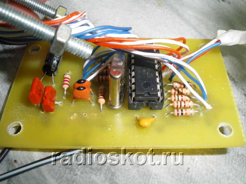
This clock is assembled on a well-known chipset - K176IE18 (binary counter for a clock with a bell signal generator),
K176IE13 (hour counter with alarm clock) and K176ID2 (converter binary code in seven-segment)
 When the power is turned on, zeros are automatically written to the hour and minute counter and the alarm clock memory register of the U2 chip. To install
time, press the S4 (Time Set) button and holding it press the S3 (Hour) button - to set the hour or S2 (Min) - to set
minutes. In this case, the readings of the corresponding indicators will begin to change with a frequency of 2 Hz from 00 to 59 and then again 00. At the moment of transition
from 59 to 00 the hour counter will increase by one. Setting the alarm time is the same, you just need to hold it
button S5 (Alarm Set). After setting the alarm time, you need to press the S1 button to turn on the alarm (contacts
closed). Button S6 (Reset) is used to force the minute indicators to be reset to 00 during setup. LEDs D3 and D4 play a role
dividing dots flashing at a frequency of 1 Hz. Digital indicators in the diagram are located in in the right order, i.e. come first
hour indicators, two dividing dots (LEDs D3 and D4) and minute indicators.
The clock used resistors R6-R12 and R14-R16 with a wattage of 0.25W, the rest - 0.125W. Quartz resonator XTAL1 at a frequency of 32 768Hz -
ordinary sentry, KT315A transistors can be replaced with any low-power silicon of the appropriate structure, KT815A - with transistors
average power with a static base current transfer coefficient of at least 40, diodes - any low-power silicon. Tweeter BZ1
dynamic, without built-in generator, winding resistance 45 Ohm. Button S1 is naturally locked.
 The indicators used are TOS-5163AG green, you can use any other indicators with a common cathode without reducing
resistance of resistors R6-R12. In the figure you can see the pinout of this indicator; the conclusions are shown conditionally, because presented
top view.
After assembling the clock, you may need to adjust the frequency crystal oscillator. This can most accurately be done by digitally controlling
using a frequency meter, the oscillation period is 1 s at pin 4 of the U1 microcircuit. Tuning the generator as the clock progresses will require significantly more expense
time. You may also have to adjust the brightness of LEDs D3 and D4 by selecting the resistance of resistor R5, so that everything
glowed uniformly brightly. The current consumed by the clock does not exceed 180 mA.
The clock is powered by regular block power supply assembled on a positive microcircuit stabilizer 7809 with an output voltage of +9V and a current of 1.5A.
You can find many on sale various models and electronic options digital clock, but most of them are designed for indoor use, since the numbers are small. However, sometimes it is necessary to place a clock on the street - for example, on the wall of a house, or in a stadium, square, that is, where it will be visible from a great distance by many people. For this purpose it was developed and successfully assembled this scheme large LED clock, to which you can connect (via internal transistor switches) LED indicators as desired large size. You can enlarge the schematic diagram by clicking on it:

Description of the clock
- Watch. IN this mode There is a standard type of time display. There is a digital correction of the clock accuracy.
- Thermometer. In this case, the device measures the temperature of the room or air outside from one sensor. Range from -55 to +125 degrees.
- Power supply control is provided.
- Displays information on the indicator alternately - a clock and a thermometer.
- To save settings and settings when 220V is lost, non-volatile memory is used.

The basis of the device is the ATMega8 MK, which is flashed by setting fuses according to the table:

Operation and clock management
When you turn on the watch for the first time, an advertising splash screen will appear on the screen, after which it will switch to displaying the time. Pressing a button SET_TIME the indicator will go in a circle from the main mode:
- minutes and seconds display mode. In this mode, if you simultaneously press the button PLUS And MINUS, then the seconds will be reset;
- setting the minutes of the current time;
- setting the current time clock;
- symbol t. Setting the duration of the clock display;
- symbol o. Display time of external temperature indication symbols (out);
- the amount of daily correction of the clock accuracy. Symbol c and correction value. Setting limits from -25 to 25 sec. The selected value will be added or subtracted from the current time every day at 0 hours 0 minutes and 30 seconds. For more details, read the instructions that are in the archive with the firmware and printed circuit board files.

Setting the clock
While holding down the buttons PLUS/MINUS We do accelerated setting of values. After changing any settings, after 10 seconds the new values will be written to non-volatile memory and will be read from there when restart nutrition. New settings take effect during installation. The microcontroller monitors the presence of main power. When it is turned off, the device is powered from internal source. The redundant power module diagram is shown below:

To reduce current consumption, the indicator, sensors and buttons are turned off, but the clock itself continues to count time. As soon as the 220V mains voltage appears, all indication functions are restored.

Since the device was conceived as a large LED clock, it has two displays: a large LED - for the street, and a small LCD - for easy setup of the main display. The large display is located several meters from the control unit and is connected by two cables of 8 wires. To control the anodes of the external indicator indicator, transistor switches are used according to the diagram given in the archive. Project authors: Alexandrovich & SOIR. I propose for repetition the circuit of a simple electronic clock with an alarm clock, made on the PIC16F628A type. The big advantage of this watch is LED indicator ALS type, to display time. Personally, I’m pretty tired of all kinds of LCDs and I want to be able to see the time from anywhere in the room, including in the dark, and not just directly with good lighting. The circuit contains a minimum of parts and has excellent repeatability. The watch was tested for a month, which showed its reliability and performance. I think of all the schemes on the Internet, this one is the easiest to assemble and run.
Schematic diagram of an electronic clock with an alarm clock on a microcontroller:

As can be seen from the clock diagram, it is the only chip used in this device. For the task clock frequency A 4 MHz quartz resonator is used. To display the time, red indicators with a common anode are used; each indicator consists of two digits with decimal points. In the case of using a piezo emitter, capacitor C1 - 100 μF can be omitted.
You can use any indicators with a common anode, as long as each digit has its own anode. To ensure that the electronic watch is clearly visible in the dark and from a great distance, try to choose a larger ALS.

The clock display is dynamic. At a given time, only one digit is displayed, which allows you to significantly reduce current consumption. The anodes of each digit are controlled by a PIC16F628A microcontroller. The segments of all four digits are connected together and, through current-limiting resistors R1 ... R8, connected to the terminals of the MK port. Since the indicator lights up very quickly, the flickering of the numbers becomes unnoticeable.

Momentary buttons are used to set minutes, hours and alarm clock. Pin 10 is used as an output for the alarm signal, and a cascade of transistors VT1,2 is used as an amplifier. The sound emitter is a piezoelectric element of the ZP type. To improve the volume, you can replace it with a small speaker.

The clock is powered from a stabilized 5V source. It can also be powered by batteries. The watch has 9 display modes. Switching between modes is carried out using the “+” and “-” buttons. Before displaying the readings themselves, a short hint about the name of the mode is displayed on the indicators. The duration of the hint display is one second.

Using the "Correction" button, the alarm clock is switched to settings mode. In this case, a short-term prompt is displayed for half a second, after which the adjusted value begins to blink. Correction of readings is carried out using the “+” and “-” buttons. When you press the button for a long time, the auto-repeat mode is activated at the specified frequency. All values, except hours, minutes and seconds, are written to EEPROM and restored after power cycle.

If no button is pressed within a few seconds, the electronic clock switches to time display mode. By pressing the "On/Off" button the alarm clock turns on or off, this action is confirmed by a short sound. When the alarm clock is on, the dot in the low-order digit of the indicator lights up. I was thinking about where to put the clock in the kitchen, and decided to mount it directly into the gas stove :) The material was sent by in_sane.
Discuss the article ELECTRONIC ALARM CLOCK
Wrist homemade watch on a vacuum indicator, made in steampunk style. Material taken from www.johngineer.com. This wristwatch is assembled on the basis of the IVL-2 display. Initially, I bought several of these indicators to create standard ones. table clock, but after some thought I realized that I could build stylish wristwatches too. The indicator has a number of features that make it more suitable for this purpose than most other Soviet displays. Here are the parameters:
- The rated filament current is 60mA 2.4V, but works with 35mA 1.2V.
- Small size - only 1.25 x 2.25"
- Can work with relatively low voltage grids 12V (up to 24)
- Consumes only 2.5 mA/segment at 12.5V
All photos can be made larger by clicking on them. The biggest obstacle to the successful completion of the project was food. Since this watch was intended to be part of a costume, it doesn’t matter that the battery only lasts 10 hours. I settled on AA and AAA.

The scheme is quite simple. Microcontroller Atmel AVR ATMega88, and real time clock - DS3231. But there are other chips, much cheaper, that will work just as well in a generator.
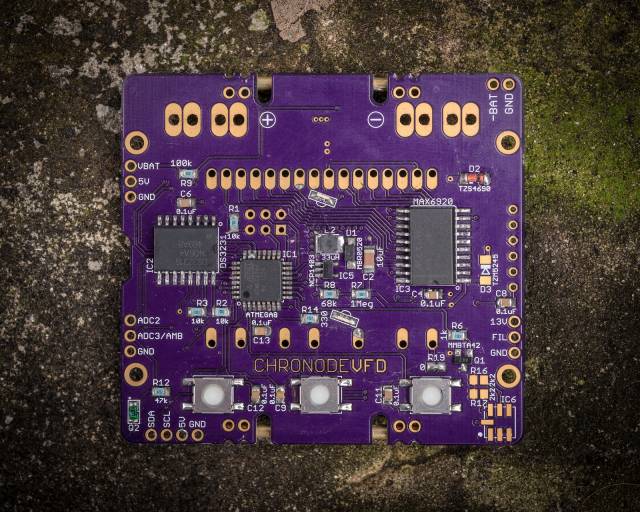
VFD display driven by MAX6920 - 12-bit shift register with high voltage(up to 70V) outputs. It is easy to use, very reliable and compact. It was also possible for the display driver to solder a bunch of discrete components, but this was impractical due to space constraints.

The battery voltage also powers a 5V boost converter (MCP1640 SOT23-6), which is needed for normal operation AVR, DS3231, and MAX6920, and also acts as the input voltage to a second boost converter (NCP1403 SOT23-5), which produces 13V for the vacuum indicator grid voltage.

The watch has three sensors: one analog and two digital. The analog sensor is a phototransistor and is used to detect the light level (Q2). Digital sensors: BMP180 - pressure and temperature, and MMA8653 - accelerometer for motion detection. Both digital sensors are connected via an I2C bus to the DS3231.

Brass tubes are soldered for beauty and protection of the glass display wristwatch, and 2 mm thick copper wires - for attaching the leather strap. Full circuit diagram is not given in the original article - see the datasheet connection to the specified microcircuits.