DIY watch with LED display. Electronic watches - Clocks - Designs for home and garden
I remember... Thirty years ago, six indicators were a small treasure. Anyone who could then make a clock using TTL logic with such indicators was considered a sophisticated expert in his field.
The glow of the gas-discharge indicators seemed warmer. After a few minutes I was wondering if these old lamps would work and wanted to do something with them. Now it is very easy to make such a watch. All you need is a microcontroller...
Since at that time I was interested in programming microcontrollers in languages high level, I decided to play a little. I tried to construct a simple clock using digital gas discharge indicators.
Purpose of design
I decided that the clock should have six digits and the time should be set with a minimum number of buttons. Additionally, I wanted to try to use a few of the most common microcontroller families different manufacturers. I intended to write the program in C.
Gas discharge indicators require high voltage to operate. But I didn’t want to deal with dangerous mains voltage. The watch was supposed to be powered by a harmless 12 V voltage.
Since my main goal was the game, you will not find any description of the mechanical design or body drawings here. If you wish, you can change the watch yourself in accordance with your tastes and experience.
Here's what I got:
- Time display: HH MM SS
- Alarm indication: HH MM --
- Time display mode: 24 hours
- Accuracy ±1 second per day (depending on quartz crystal)
- Supply voltage: 12 V
- Current consumption: 100 mA
Clock diagram
For a device with a six-digit digital display, multiplex mode was a natural solution.
The purpose of most elements of the block diagram (Figure 1) is clear without comment. To a certain extent, a non-standard task was to create a TTL level converter into high-voltage indicator control signals. The anode drivers are made using high-voltage NPN and PNP transistors. The diagram is borrowed from Stefan Kneller (http://www.stefankneller.de).
The 74141 TTL chip contains a BCD decoder and a high-voltage driver for each digit. It may be difficult to order one chip. (Although I don't know if anyone makes them anymore). But if you find gas-discharge indicators, 74141 may be somewhere nearby :-). At the time of TTL logic, there was practically no alternative to the 74141 chip. So try to find one somewhere.
The indicators require a voltage of about 170 V. It makes no sense to develop a special circuit for a voltage converter, since there are a huge number of boost converter chips. I chose the inexpensive and widely available IC34063. The converter circuit is almost completely copied from technical description MC34063. A T13 power switch has just been added to it. The internal switch is not suitable for such high voltage. I used a choke as inductance for the converter. It is shown in Figure 2; its diameter is 8 mm and its length is 10 mm.
The efficiency of the converter is quite good, and the output voltage is relatively safe. With a load current of 5 mA, the output voltage drops to 60 V. R32 acts as a current-measuring resistor.
To power the logic, linear regulator U4 is used. There is space on the diagram and on the board for backup battery. (3.6 V - NiMH or NiCd). D7 and D8 are Schottky diodes, and resistor R37 is designed to limit the charging current according to the characteristics of the battery. If you are building watches just for fun, you won't need the battery, D7, D8 and R37.
The final circuit is shown in Figure 3.
| Figure 3. | ||
The time setting buttons are connected via diodes. The state of the buttons is checked by setting a logical “1” at the corresponding output. As a bonus feature, a piezo emitter is connected to the output of the microcontroller. To shut up that nasty squeak, use a small switch. A hammer would be quite suitable for this, but this is a last resort :-).
List of circuit components, figure printed circuit board and the layout diagram can be found in the "Downloads" section.
CPU
Almost any microcontroller with a sufficient number of pins, the minimum required number of which is indicated in Table 1, can control this simple device.
| Table 1. | ||||||||||||||||
|
Each manufacturer develops its own families and types of microcontrollers. The location of the pins is individual for each type. I tried to design a universal board for several types of microcontrollers. The board has a 20-pin socket. With a few jumper wires you can adapt it to different microcontrollers.
The microcontrollers tested in this circuit are listed below. You can experiment with other types. The advantage of the scheme is the ability to use different processors. Radio amateurs, as a rule, use one family of microcontrollers and have the appropriate programmer and software tools. There may be problems with microcontrollers from other manufacturers, so I gave you the opportunity to choose a processor from your favorite family.
All the specifics of switching on various microcontrollers are reflected in Tables 2...5 and Figures 4...7.
| Table 2. | ||||||||||||
|
Note: A 10 MΩ resistor is connected in parallel with the quartz resonator.
| Table 3. | ||||||||||||
|
Note: The microcircuit must be rotated 180° in the socket.
| Table 4. | ||||||||||||
|
Note: Add SMD components R and C to the RESET pin (10 kΩ and 100 nF).
| Table 5. | ||||||||||||
|
Note: Add SMD components R and C to the RESET pin (10 kΩ and 100 nF); connect the pins marked with asterisks to the +Ub power bus via 3.3 kOhm SMD resistors.
When you compare the codes for different microcontrollers, you will see that they are very similar. There are differences in access to ports and definition of interrupt functions, as well as in what depends on the hardware components.
The source code consists of two sections. Function main() configures ports and starts a timer that generates interrupt signals. After this, the program scans the pressed buttons and sets the appropriate time and alarm values. There, in the main loop, the current time is compared with the alarm clock and the piezo emitter is turned on.
The second part is a subroutine for handling timer interrupts. A subroutine that is called every millisecond (depending on the timer's capabilities) increments the time variables and controls the display digits. In addition, the status of the buttons is checked.
Running the circuit
When installing components and setting up, start with the power source. Solder the U4 regulator and surrounding components. Check for 5 V voltage for U2 and 4.6 V for U1. The next step is to assemble the high voltage converter. Use trimming resistor R36 to set the voltage to 170 V. If the adjustment range is not enough, slightly change the resistance of resistor R33. Now install the U2 chip, transistors and resistors of the anode and digital driver circuit. Connect the U2 inputs to the GND bus and connect one of the resistors R25 - R30 in series to the +Ub power bus. The indicator numbers should light up in the corresponding positions. At the last stage of checking the circuit, connect pin 19 of the U1 microcircuit to ground - the piezo emitter should beep.
Source codes and compiled programs can be found in the corresponding ZIP file in the "Downloads" section. After flashing the program into the microcontroller, carefully check each pin in position U1 and install the necessary wire and solder jumpers. Refer to the microcontroller images above. If the microcontroller is programmed and connected correctly, its generator should start working. You can set the time and alarm. Attention! There is space on the board for one more button - this is a spare button for future expansions :-).
Check generator frequency accuracy. If it is not within the expected range, slightly change the values of capacitors C1 and C2. (Solder small capacitors in parallel or replace them with others). The accuracy of the watch should improve.
Conclusion
Small 8-bit processors are quite suitable for high-level languages. C was not originally intended for small microcontrollers, but simple applications you can use it perfectly. Assembler would be better suited for complex tasks that require critical times or maximum processor load. For most radio amateurs, both free and shareware limited versions of the C compiler are suitable.
C programming is the same for all microcontrollers. You must know the hardware functions (registers and peripherals) of the selected type of microcontroller. Be careful with bit operations - the C language is not suitable for manipulating individual bits, as can be seen in the example of the original when for ATtiny.
Are you done? Then tune in to contemplate the vacuum tubes and watch...
...the old days are back... :-)
Editor's note
A complete analogue of SN74141 is the K155ID1 microcircuit, produced by the Minsk Integral software.
The microcircuit can be easily found on the Internet.
The photo shows a prototype that I assembled to debug the program that will manage this entire facility. The second arduino nano in the upper right corner of the breadboard does not belong to the project and sticks out there just like that, you don’t have to pay attention to it. 
A little about the principle of operation: Arduino takes data from the DS323 timer, processes it, determines the light level using a photoresistor, then sends everything to the MAX7219, and it, in turn, lights up the required segments with the required brightness. Also, using three buttons, you can set the year, month, day, and time as desired. In the photo, the indicators display time and temperature, which is taken from a digital temperature sensor
The main difficulty in my case is that the 2.7-inch indicators have a common anode, and they had to, firstly, somehow make friends with the max7219, which is designed for indicators with a common cathode, and secondly, solve the problem with their power supply, since they need 7.2 volts for glow, which max7219 alone cannot provide. Having asked for help on one forum, I received an answer.
Solution in the screenshot: 
A microcircuit is attached to the outputs of the segments from max7219, which inverts the signal, and a circuit of three transistors is attached to each output, which should be connected to the common cathode of the display, which also invert its signal and increase the voltage. Thus, we get the opportunity to connect displays with a common anode and a supply voltage of more than 5 volts to the max7219
I connected one indicator for the test, everything works, nothing smokes 
Let's start collecting.
I decided to divide the circuit into 2 parts due to the huge number of jumpers in the version that was separated by my crooked paws, where everything was on one board. The clock will consist of a display unit and a power and control unit. It was decided to collect the latter first. I ask aesthetes and experienced radio amateurs not to faint because of the cruel treatment of parts. I have no desire to buy a printer for the sake of LUT, so I do it the old fashioned way - I practice on a piece of paper, drill holes according to a template, draw paths with a marker, then etch.The principle of attaching indicators remained the same as on.
We mark the position of the indicators and components using a plexiglass template made for convenience.
Markup process


Then using a template we drill holes in in the right places and try on all the components. Everything fit perfectly.

We draw paths and etch. 

bathing in ferric chloride 
Ready!
control board: 
indication board: 
The control board turned out great, the track on the display board was not critically eaten up, it can be fixed, it’s time to solder. This time I lost my SMD virginity and included 0805 components in the circuit. At the very least, the first resistors and capacitors were soldered into place. I think I'll get better at it, it will be easier.
For soldering I used flux that I bought. Soldering with it is a pleasure; now I use alcohol rosin only for tinning.
Here ready-made boards. The control board has a seat for an Arduino nano, a clock, as well as outputs for connecting to the display board and sensors (a photoresistor for auto-brightness and a digital thermometer ds18s20) and a power supply with adjustable output voltage (for large seven-segment devices) and for powering the clock and Arduino, on the display board there are mounting sockets for displays, sockets for max2719 and uln2003a, a solution for powering four large seven-segment devices and a bunch of jumpers.


rear control board 
Rear display board: 
Terrible smd installation: 
Launch
After soldering all the cables, buttons and sensors, it's time to turn it all on. The first launch revealed several problems. The last large indicator did not light up, and the rest glowed dimly. I dealt with the first problem by soldering the leg of the SMD transistor, with the second by adjusting the voltage produced by lm317.IT'S ALIVE!

This clock is assembled on a well-known chipset - K176IE18 (binary counter for a clock with a bell signal generator),
K176IE13 (hour counter with alarm clock) and K176ID2 (converter binary code to seven-segment)
 When the power is turned on, zeros are automatically written to the hour and minute counter and the alarm clock memory register of the U2 chip. To install
time, press the S4 (Time Set) button and holding it press the S3 (Hour) button - to set the hour or S2 (Min) - to set
minutes. In this case, the readings of the corresponding indicators will begin to change with a frequency of 2 Hz from 00 to 59 and then again 00. At the moment of transition
from 59 to 00 the hour counter will increase by one. Setting the alarm time is the same, you just need to hold it
button S5 (Alarm Set). After setting the alarm time, you need to press the S1 button to turn on the alarm (contacts
closed). Button S6 (Reset) is used to force the minute indicators to be reset to 00 during setup. LEDs D3 and D4 play a role
dividing dots flashing at a frequency of 1 Hz. Digital indicators in the diagram are located in in the right order, i.e. come first
hour indicators, two dividing dots (LEDs D3 and D4) and minute indicators.
The clock used resistors R6-R12 and R14-R16 with a wattage of 0.25W, the rest - 0.125W. Quartz resonator XTAL1 at a frequency of 32 768Hz -
an ordinary clock, KT315A transistors can be replaced with any low-power silicon of the appropriate structure, KT815A - with transistors
average power with a static base current transfer coefficient of at least 40, diodes - any low-power silicon. Tweeter BZ1
dynamic, without built-in generator, winding resistance 45 Ohm. Button S1 is naturally locked.
 The indicators used are TOS-5163AG green, you can use any other indicators with a common cathode without reducing
resistance of resistors R6-R12. In the figure you can see the pinout of this indicator; the conclusions are shown conditionally, because presented
top view.
After assembling the clock, you may need to adjust the frequency crystal oscillator. This can most accurately be done by digitally controlling
using a frequency meter, the oscillation period is 1 s at pin 4 of the U1 microcircuit. Tuning the generator as the clock progresses will require significantly more expense
time. You may also have to adjust the brightness of LEDs D3 and D4 by selecting the resistance of resistor R5, so that everything
glowed uniformly brightly. The current consumed by the clock does not exceed 180 mA.
The clock is powered by regular block power supply assembled on a positive microcircuit stabilizer 7809 with an output voltage of +9V and a current of 1.5A.
Large LED clock
Introduction.
It all started like this. At my dacha I had an old mechanical alarm clock (made in USSR), which had mechanical problems. I decided to build an electronic watch. The first problem is which indicator to choose. VLI and GRI are not suitable due to large temperature differences at the dacha. The LCD is no longer needed for the same reason. Remains LED indicator. I'm tired of looking at small numbers on indicators, and large seven-segment indicators are rare and expensive. It was decided to make an indicator with a digit height of 50mm from individual green LEDs.
We figured out the indicator, but it needs to be managed somehow. In this case, the clock should run even if there is no power for a long time. We will do it on an ATTiny2313 MK and an RTC DS1307 chip, which also has a built-in power controller and allows you to connect a battery.
1. Indicator.
We will make it, as I already said, from individual green LEDs with a diameter of 5mm. Here is the indicator diagram:
There's not much to explain here. Current-limiting resistors, diodes are needed for beautiful drawing of numbers. Each rectangle in the diagram should have one digit (the diagram is the same for all), with a separating colon in the middle.
2. Main part.
The circuit, as I already said, is based on ATTiny2313 and DS1307. Here it is:

This requires some explanation. On the right are two dual seven-segment devices and two LEDs - the internal circuit of a small indicator with OA. Why two indicators? At night there is a big indicator bright glow may interfere with sleep (the clock will be near the bed), so the indication can be switched to a small indicator using switch SW1. In the "Night" position A small indicator works in the "Day" position. - big. I got this little indicator from washing machine, the pinout is on the stove. 3V battery, CR2032. Transistors Q1-Q4 can be replaced with any other low-power ones PNP transistors, for example on KT315. Q6-Q9 - on PNP with a CE current of at least 1A, Q5 - on NPN with a collector current of at least 0.4A. The power supply can be any with a voltage of 9-20V, the polarity is not important, you can even use alternating voltage. Current not less than 1A. The U4 stabilizer must be installed on the radiator. By the way, the lower the input voltage, the easier life is for the stabilizer. My BP is like this:

Now let's move on to assembly.
3. Assembly.
Let's go to the store and buy parts.

We make boards and start soldering. Soldering 88 LEDs, the same number of resistors and 44 diodes is not easy, but it is worth it.


Now we connect everything with wires. I use PLS/PBS cables and connectors. These pictures will help you:


Now we are flashing the MK. Here are the fuses:

And turn on:


The buttons and connectors I used are:

4. Body.
I made the body from plywood and a 20*40 block, sanded it and varnished it. I installed two fasteners on the back for wall mounting.

By the way, to seal the indicator windows I used film from green bottles, it looks beautiful and protects from sun exposure.
Now some photos:


Wrist homemade watch on a vacuum indicator, made in steampunk style. Material taken from www.johngineer.com. This wristwatch is assembled on the basis of the IVL-2 display. Initially, I bought several of these indicators to create standard ones. table clock, but after thinking about it I realized that I could build stylish wristwatches too. The indicator has a number of features that make it more suitable for this purpose than most other Soviet displays. Here are the parameters:
- The rated filament current is 60mA 2.4V, but works with 35mA 1.2V.
- Small size - only 1.25 x 2.25"
- Can work with relatively low voltage grids 12V (up to 24)
- Consumes only 2.5 mA/segment at 12.5V
All photos can be made larger by clicking on them. The biggest obstacle to the successful completion of the project was food. Since this watch was intended to be part of a costume, it doesn’t matter that the battery only lasts 10 hours. I settled on AA and AAA.

The scheme is quite simple. Microcontroller Atmel AVR ATMega88, and real time clock - DS3231. But there are other chips, much cheaper, that will work just as well in a generator.
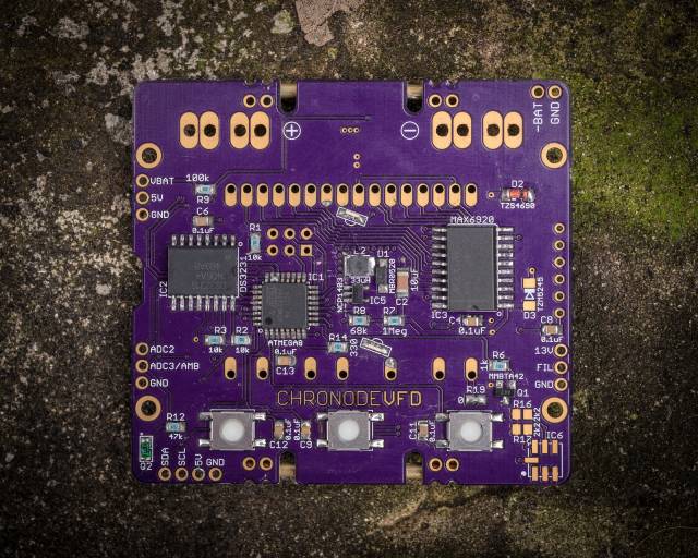
VFD display driven by MAX6920 - 12-bit shift register with high voltage(up to 70V) outputs. It is easy to use, very reliable and compact. It was also possible for the display driver to solder a bunch of discrete components, but this was impractical due to space constraints.

The battery voltage also powers a 5V boost converter (MCP1640 SOT23-6), which is needed for normal operation AVR, DS3231, and MAX6920, and also acts as the input voltage to a second boost converter (NCP1403 SOT23-5), which produces 13V for the vacuum indicator grid voltage.

The watch has three sensors: one analog and two digital. The analog sensor is a phototransistor and is used to detect the light level (Q2). Digital sensors: BMP180 - pressure and temperature, and MMA8653 - accelerometer for motion detection. Both digital sensors are connected via an I2C bus to the DS3231.

Brass tubes are soldered for beauty and protection of the glass display wristwatch, and 2 mm thick copper wires - for attaching a leather strap. Full circuit diagram is not given in the original article - see the datasheet connection to the specified microcircuits.