Assemble an electronic watch with your own hands. Large LED clock
I propose for repetition the circuit of a simple electronic clock with an alarm clock, made on the PIC16F628A type. The big advantage of this watch is LED indicator ALS type, to display time. Personally, I’m pretty tired of all kinds of LCDs and I want to be able to see the time from anywhere in the room, including in the dark, and not just directly with good lighting. The circuit contains a minimum of parts and has excellent repeatability. The watch was tested for a month, which showed its reliability and performance. I think of all the schemes on the Internet, this one is the easiest to assemble and run.Schematic diagram of an electronic clock with an alarm clock on a microcontroller:

As can be seen from the clock diagram, it is the only microcircuit used in this device. For the task clock frequency A 4 MHz quartz resonator is used. To display the time, red indicators with a common anode are used; each indicator consists of two digits with decimal points. In the case of using a piezo emitter, capacitor C1 - 100 μF can be omitted.
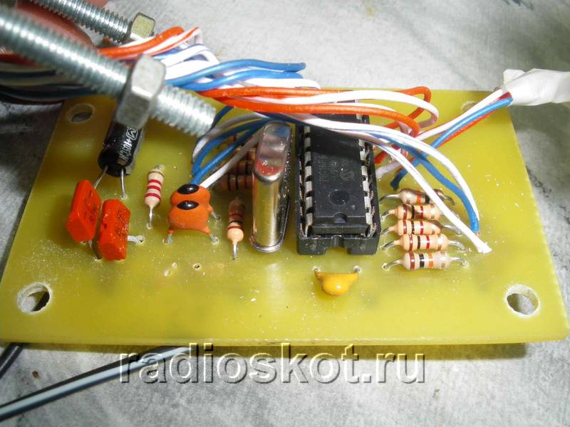
You can use any indicators with a common anode, as long as each digit has its own anode. So that electronic watch were clearly visible in the dark and from a great distance - try to choose the larger ALS ones.

The clock display is dynamic. At a given time, only one digit is displayed, which allows you to significantly reduce current consumption. The anodes of each digit are controlled by a PIC16F628A microcontroller. The segments of all four digits are connected together and, through current-limiting resistors R1 ... R8, connected to the terminals of the MK port. Since the indicator lights up very quickly, the flickering of the numbers becomes unnoticeable.

Momentary buttons are used to set minutes, hours and alarm clock. Pin 10 is used as an output for the alarm signal, and a cascade of transistors VT1,2 is used as an amplifier. The sound emitter is a piezoelectric element of the ZP type. To improve the volume, you can replace it with a small speaker.

The clock is powered from a stabilized 5V source. It can also be powered by batteries. The watch has 9 display modes. Switching between modes is carried out using the “+” and “-” buttons. Before displaying the readings themselves, a short hint about the name of the mode is displayed on the indicators. The duration of the hint display is one second.
Using the "Correction" button, the alarm clock is switched to settings mode. In this case, a short-term prompt is displayed for half a second, after which the adjusted value begins to blink. Correction of readings is carried out using the “+” and “-” buttons. When you press the button for a long time, the auto-repeat mode is activated at the specified frequency. All values, except hours, minutes and seconds, are written to EEPROM and restored after power cycle.

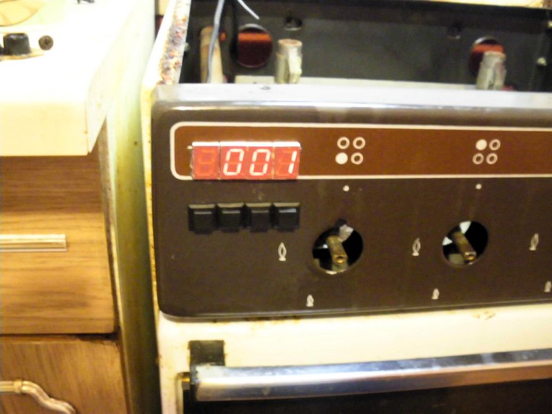
If no button is pressed within a few seconds, the electronic clock switches to time display mode. By pressing the "On/Off" button the alarm clock turns on or off, this action is confirmed by a short sound. When the alarm clock is on, the dot in the low-order digit of the indicator lights up. I was thinking about where to put the clock in the kitchen, and decided to mount it directly into the gas stove :) The material was sent by in_sane.
Discuss the article ELECTRONIC ALARM CLOCK
You can find many on sale various models and electronic options digital clock, but most of them are designed for indoor use, since the numbers are small. However, sometimes it is necessary to place a clock on the street - for example, on the wall of a house, or in a stadium, square, that is, where it will be visible from a great distance by many people. For this purpose it was developed and successfully assembled this scheme large LED clock, to which you can connect (via internal transistor switches) LED indicators as desired large size. Increase schematic diagram you can click on it:

Description of the clock
- Watch. IN this mode There is a standard type of time display. There is a digital correction of the clock accuracy.
- Thermometer. In this case, the device measures the temperature of the room or air outside from one sensor. Range from -55 to +125 degrees.
- Power supply control is provided.
- Displays information on the indicator alternately - a clock and a thermometer.
- To save settings and settings when 220V is lost, non-volatile memory is used.

The basis of the device is the ATMega8 MK, which is flashed by setting fuses according to the table:

Operation and clock management
When you turn on the watch for the first time, an advertising splash screen will appear on the screen, after which it will switch to displaying the time. Pressing a button SET_TIME the indicator will go in a circle from the main mode:
- minutes and seconds display mode. If in this mode you simultaneously press the button PLUS And MINUS, then the seconds will be reset;
- setting the minutes of the current time;
- setting the current time clock;
- symbol t. Setting the duration of the clock display;
- symbol o. Display time of external temperature indication symbols (out);
- the amount of daily correction of the clock accuracy. Symbol c and correction value. Setting limits from -25 to 25 sec. The selected value will be added or subtracted from the current time every day at 0 hours 0 minutes and 30 seconds. For more details, read the instructions that are in the archive with the firmware and printed circuit board files.

Setting the clock
While holding down the buttons PLUS/MINUS We do accelerated setting of values. After changing any settings, after 10 seconds the new values will be written to non-volatile memory and will be read from there when restart nutrition. New settings take effect during installation. The microcontroller monitors the presence of main power. When it is turned off, the device is powered from internal source. The redundant power module diagram is shown below:

To reduce current consumption, the indicator, sensors and buttons are turned off, but the clock itself continues to count time. As soon as the 220V mains voltage appears, all indication functions are restored.

Since the device was conceived as large led clock, they have two displays: a large LED - for the street, and a small LCD - for easy setup of the main display. The large display is located at a distance of several meters from the control unit and is connected by two cables of 8 wires. To control the anodes of the external indicator indicator, transistor switches are used according to the diagram given in the archive. Project authors: Alexandrovich & SOIR. Even in my youth, I wanted to assemble an electronic watch. It seemed to me that assembling a watch was the pinnacle of skill. As a result, I assembled a clock with a calendar and an alarm clock on the K176 series. Now they are already obsolete and I wanted to put together something more modern. After a long search on the Internet (I never thought that I was so difficult to please;)) I liked this scheme. The difference from the above circuit is that a rare microcircuit is not used TRIC6V595, and its composite and more powerful analogue on microcircuits 74HC595 And ULN2003. Corrections to the diagram are given below.

Scheme of an electronic LED clock running line
Dear author of the diagram OLED, the firmware is also his. The clock displays the current time, year, month and day of the week, as well as the temperature outside and inside the house with a ticker. They have 9 independent alarms. It is possible to adjust (correct) the stroke + - minute per day, select the speed of the line, change the brightness of the LEDs, depending on the time of day.

If there is a power outage, the watch is powered either by an ionistor (a capacity of 1 Farad is enough for 4 days of operation) or by a battery. Whoever likes it, the board is designed to install both. They have a very convenient and understandable control menu (all controls are performed with just two buttons). The following parts are used in the watch (all parts are in SMD cases):
Microcontroller AtMEGA 16A
-
Shift register 74HC595
-
Chip ULN2803(eight Darlington keys)
-
Temperature sensors DS18B20(installed upon request)
-
25 resistors at 75 Ohm (type 0805)
-
3 resistors 4.7kOhm
-
2 resistors 1.5 kOhm
-
1 resistor 3.6 kOhm
-
6 SMD capacitors with a capacity of 0.1 uF
-
1 capacitor 220 µF
-
Hour quartz at a frequency of 32768 hertz.
-
Matrices 3 pieces brand 23088-ASR 60x60 mm - common cathode
-
Any 5 volt buzzer.


Printed circuit board for electronic LED clock ticking line
For residents of Ukraine, I’ll tell you, the matrices are available in the Lugansk Radio Market store. The advantages of watches over other similar devices are a minimum of parts and high repeatability. The LED clock starts working immediately after the firmware is installed, unless of course there are no mistakes in the installation. The microcontroller is flashed in-circuit; for this purpose, special pins are provided on the board. I flashed it with Poniprog. Fuse screens for programs ponyprog And AVR are given below, the firmware files are also posted in Ukrainian and Russian, which is more familiar to whom.

If you do not need temperature sensors, then you do not need to install them. The clock automatically recognizes the connection of sensors, and if one or both sensors are missing, the device simply stops displaying the temperature (if one sensor is missing, the outside temperature is not displayed, if both are missing, the temperature is not displayed at all).
Homemade housing for LED watches


A video is provided to demonstrate the operation of the watch, it is not high quality, since it was filmed with a camera, but that’s what it is.
Video of the clock working
I have already collected four copies of these watches, and I give each one as a birthday present to my relatives. And everyone really liked them. If you also want to collect this watch and have any questions, you are welcome to visit our forum. Sincerely, Voitovich Sergey ( Sergey-78 ).
Discuss the article ELECTRONIC LED CLOCK
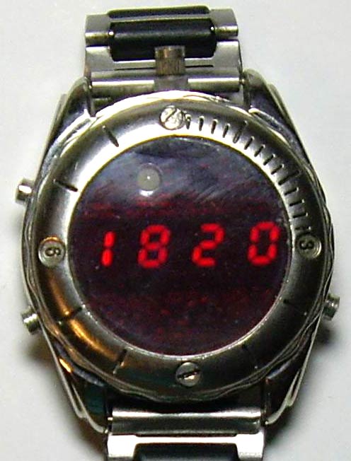
As the name suggests, the main purpose of this device- find out the current time and date. But it has many more useful functions. The idea for its creation appeared after I came across a half-broken watch with a relatively large (for a wrist) metal case. I thought I could put it in there homemade watch, the possibilities of which are limited only by your own imagination and skill. The result was a device with the following functions:
1. Clock - calendar:
- Leap years are taken into account
Counting and displaying hours, minutes, seconds, day of the week, date, month, year.
Availability automatic adjustment current time, which is produced every hour ( maximum values+/-9999 units, 1 unit. = 3.90625 ms.)
Calculating the day of the week from a date (for the current century)
Automatic changeover to daylight saving time winter time(disabled)
2. Two independent alarm clocks (a melody sounds when triggered)
3. Timer with 1 second increments. (Maximum counting time 99h 59m 59s)
4. Two-channel stopwatch with counting resolution of 0.01 sec. ( maximum time counts 99h 59m 59s)
5. Stopwatch with counting resolution of 1 second. (maximum counting time 99 days)
6. Thermometer in the range from -5°C. up to 55°C (limited by temperature range normal operation devices) in increments of 0.1°C.
7. Reader and emulator electronic keys- tablets of the DS1990 type using the Dallas 1-Wire protocol (memory for 50 pieces, which already contains several universal “all-terrain keys”) with the ability to view the key code byte by byte.
8. Remote control control on IR rays (only the "Take a picture" command is implemented) for digital cameras "Pentax", "Nikon", "Canon"
9. LED flashlight
10. 7 melodies
11. Sound signal at the beginning of every hour (can be switched off)
12. Sound confirmation of button presses (can be switched off)
13. Battery voltage monitoring with calibration function
14. Digital indicator brightness adjustment
Maybe such functionality is redundant, but I like universal things, and plus the moral satisfaction that this watch will be made with my own hands.
Schematic diagram of the clock
The device is built on the ATmega168PA-AU microcontroller. The clock ticks according to timer T2, operating in asynchronous mode from a clock quartz at 32768 Hz. The microcontroller is in sleep mode almost all the time (the indicator is off), waking up once a second to add this very second to the current time and falls asleep again. In active mode, the MK is clocked from the internal RC oscillator at 8 MHz, but the internal prescaler divides it by 2, as a result, the core is clocked at 4 MHz. For indication, four single-digit LED digital seven-segment indicators with a common anode and a decimal point are used. There are also 7 status LEDs, the purpose of which is as follows:
D1- Negative value sign (minus)
D2- Sign of a running stopwatch (flashing)
D3- Sign of the first alarm clock being turned on
D4- Sign of the second alarm being turned on
D5- Feed indicator sound signal at the beginning of every hour
D6- Sign of a running timer (flashing)
D7- Sign low voltage power batteries
R1-R8 - current-limiting resistors of segments of digital indicators HG1-HG4 and LEDs D1-D7. R12,R13 – divider for monitoring battery voltage. Since the clock supply voltage is 3V, and the white LED D9 requires about 3.4-3.8V at rated current consumption, it does not glow at full strength (but it is enough to avoid stumbling in the dark) and is therefore connected without a current-limiting resistor. Elements R14, Q1, R10 are designed to control the infrared LED D8 (implementation remote control for digital cameras). R19, R20, R21 are used for pairing when communicating with devices that have a 1-Wire interface. Control is carried out by three buttons, which I conventionally called: MODE (mode), UP (up), DOWN (down). The first of them is also designed to wake up the MK by an external interrupt (in this case the indication turns on), so it is connected separately to the PD3 input. The pressing of the remaining buttons is determined using an ADC and resistors R16, R18. If the buttons are not pressed within 16 seconds, the MK goes to sleep and the indicator goes off. When in mode “Remote control for cameras” this interval is 32 seconds, and with the flashlight on - 1 minute. MK can also be put to sleep manually using the control buttons. When the stopwatch is running with a count resolution of 0.01 sec. The device does not go into sleep mode.
PCB
The device is assembled on a double-sided printed circuit board of a round shape according to the size of the internal diameter of the case wristwatch. But in production I used two single-sided boards with a thickness of 0.35 mm. This thickness was again obtained by peeling it off from double-sided fiberglass laminate with a thickness of 1.5 mm. The boards were then glued together. All this was done because I did not have thin double-sided fiberglass, and every millimeter of thickness saved in the limited internal space of the watch case is very valuable, and there was no need for alignment in the manufacture of printed conductors using the LUT method. Drawing printed circuit board and location of parts are in the attached files. On one side there are indicators and current-limiting resistors R1-R8. On the back are all the other details. There are two through holes for white and infrared LEDs.
The button contacts and battery holder are made of flexible spring sheet steel with a thickness of 0.2...0.3 mm. and tinned. Below are photos of the board from both sides:


Design, parts and their possible replacement
The ATmega168PA-AU microcontroller can be replaced with ATmega168P-AU, ATmega168V-10AU ATmega168-20AU. Digital indicators - 4 pieces KPSA02-105 super-bright red glow with a digit height of 5.08 mm. Can be supplied from the same series KPSA02-xxx or KCSA02-xxx. (just not green ones - they will glow faintly) I am not aware of other analogues of similar sizes with decent brightness. In HG1, HG3, the connection of the cathode segments is different from HG2, HG4, because it was more convenient for me for wiring the printed circuit board. In this regard, a different character generator table is used for them in the program. Used resistors and capacitors SMD for surface mounting of standard sizes 0805 and 1206, LEDs D1-D7 of standard size 0805. White and infrared LEDs with a diameter of 3 mm. The board has 13 through holes into which jumpers must be installed. A DS18B20 with a 1-Wire interface is used as a temperature sensor. LS1 is a regular piezoelectric tweeter, inserted into the lid. With one contact it is connected to the board using a spring installed on it, and with the other it is connected to the watch body by the cover itself. Quartz resonator from a wristwatch.
Programming, firmware, fuses
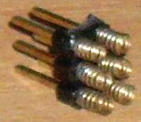
For in-circuit programming, the board has only 6 round contact spots (J1), since a full connector does not fit in height. I connected them to the programmer using a contact device made from a PLD2x3 pin plug and springs soldered onto them, pressing them with one hand to the spots. Below is a photo of the device.
I used it because during the debugging process I had to reflash the MK many times. When flashing one-time firmware, it is easier to solder thin wires connected to the programmer to the patches, and then unsolder them again. It is more convenient to flash the MK without a battery, but so that the power comes either from external source+3V, or from a programmer with the same supply voltage. The program is written in assembler in the VMLAB 3.15 environment. Source codes, firmware for FLASH and EEPROM in the application.
The FUSE bits of the DD1 microcontroller must be programmed as follows:
CKSEL3...0 = 0010 - clocking from internal RC oscillator 8 MHz;
SUT1...0 =10 - Start-up time: 6 CK + 64 ms;
CKDIV8 = 1 - frequency divider by 8 is disabled;
CKOUT = 1 - Output Clock on CKOUT disabled;
BODLEVEL2…0 = 111 - supply voltage control is disabled;
EESAVE = 0 - erasing EEPROM when programming the crystal is prohibited;
WDTON = 1 - No always on Watchdog Timer;
The remaining FUSE bits are best left untouched. The FUSE bit is programmed if set to “0”.
Flashing the EEPROM with the dump included in the archive is required.
The first cells of the EEPROM contain the initial parameters of the device. The table below describes the purpose of some of them, which can be changed within reasonable limits.
|
Cell address |
Purpose |
Parameter |
Note |
|
|
The amount of battery voltage at which a low level signal occurs |
260 ($104) (2.6V) |
|||
|
coefficient for correcting the value of the measured battery voltage |
||||
|
time interval for switching to sleep mode |
1 unit = 1 sec |
|||
|
time interval for switching to sleep mode when the flashlight is on |
1 unit = 1 sec |
|||
|
time interval for switching to sleep mode when in remote control mode for cameras |
1 unit = 1 sec |
|||
|
IButton key numbers are stored here |
Small explanations on points:
1 point. This indicates the voltage level on the battery at which the LED will light up, signaling its low value. I set it to 2.6V (parameter - 260). If you need something else, for example 2.4V, then you need to write 240 ($00F0). The low byte is stored in the cell at address $0000, and the high byte is stored in $0001.
2 point. Since I did not install a variable resistor on the board to adjust the accuracy of the battery voltage measurement due to lack of space, I introduced software calibration. The calibration procedure for accurate measurement is as follows: initially, the coefficient 1024 ($400) is written in this EEPROM cell, you need to switch the device to active mode and look at the voltage on the indicator, and then measure the real voltage on the battery with a voltmeter. The correction factor (K), which must be set, is calculated by the formula: K=Uр/Ui*1024 where Uр is the real voltage measured by the voltmeter, Ui is the voltage that was measured by the device itself. After calculating the “K” coefficient, it is entered into the device (as stated in the operating instructions). After calibration, my error did not exceed 3%.
3 point. Here you can set the time after which the device will go into sleep mode if no buttons are pressed. Mine costs 16 seconds. If, for example, you need to fall asleep in 30 seconds, then you need to write down 30 ($26).
In points 4 and 5 the same.
6 point. At address $0030 the zero key family code (Dallas 1-Wire) is stored, then its 48-bit number and CRC. And so 50 keys in sequence.
Setup, operating features
Setting up the device comes down to calibrating the battery voltage measurement, as described above. It is also necessary to detect the deviation of the clock rate for 1 hour, calculate and enter the appropriate correction value (the procedure is described in the operating instructions).
The device is powered by lithium battery CR2032 (3V) and consumes approximately 4 µA in sleep mode, and 5...20 mA in active mode, depending on the brightness of the indicator. With daily five-minute use active mode The battery should last approximately 2...8 months depending on brightness. The watch case is connected to the battery negative.
Key reading was tested on the DS1990. Emulation has been tested on METAKOM intercoms. Under serial numbers from 46 to 49 (last 4) are flashed (all keys are stored in EEPROM, they can be changed before flashing) universal keys for intercoms. The key registered under number 49 opened all the METAKOM intercoms that I came across, I did not have a chance to test the rest of the universal keys, I took their codes from the network.
Remote control for cameras was tested on Pentax optio L20 and Nikon D3000 models. Canon could not be obtained for review.
The user manual takes up 13 pages, so I did not include it in the article, but included it in an appendix in PDF format.

The archive contains:
Scheme in and GIF;
Drawing of the printed circuit board and arrangement of elements in the format;
Firmware and source code in assembler;
List of radioelements
| Designation | Type | Denomination | Quantity | Note | Shop | My notepad |
|---|---|---|---|---|---|---|
| DD1 | MK AVR 8-bit | ATmega168PA | 1 | PA-AU | To notepad | |
| U2 | Temperature sensor | DS18B20 | 1 | To notepad | ||
| Q1 | MOSFET transistor | 2N7002 | 1 | To notepad | ||
| C1, C2 | Capacitor | 30 pF | 2 | To notepad | ||
| C3, C4 | Capacitor | 0.1 µF | 2 | To notepad | ||
| C5 | Electrolytic capacitor | 47 µF | 1 | To notepad | ||
| R1-R8, R17 | Resistor | 100 Ohm | 9 | To notepad | ||
| R9 | Resistor | 10 kOhm | 1 | To notepad | ||
| R10 | Resistor | 8.2 Ohm | 1 | To notepad | ||
| R11 | Resistor | 300 Ohm | 1 | To notepad | ||
| R12 | Resistor | 2 MOhm | 1 | To notepad | ||
| R13 | Resistor | 220 kOhm | 1 | To notepad | ||
| R14 | Resistor | 30 kOhm | 1 | To notepad | ||
| R15, R19 | Resistor | 4.7 kOhm | 2 | To notepad | ||
| R16 | Resistor | 20 kOhm | 1 |
Clock from LED backlight and a pulsating minute hand on the Arduino microcontroller
This unique watch with LED backlight and pulsating minute hand was made using the TLC5940 PWM controller chip. Its main task is to expand the number of PWM modulation contacts. Another feature of this watch is that it has converted an analog voltmeter into a device that measures minutes. To do this, a new scale was printed on a standard printer and pasted on top of the old one. As such, the 5th minute is not counted, it’s just that during the fifth minute the time counter shows the arrow pointing to the end of the scale (off scale). The main control is implemented on the Arduino Uno microcontroller.

To ensure that the clock backlight did not glow too brightly in a dark room, a circuit was implemented to automatically adjust the brightness depending on the illumination (a photoresistor was used).
Step 1: Required Components


Here's what you'll need:
- 5V DC analog voltmeter module;
- Microcontroller Arduino UNO or another suitable Arduino;
- Assembly Arduino board(proto board);
- DS1307 Real Time Clock (RTC) module;
- Module with PWM controller TLC5940;
- Petal LED backlights – 12 pcs.;
- Components for assembling an automatic brightness control (LDR) circuit.
Also, for the production of some other components of the project, it is desirable to have access to a 3D printer and a laser cutting machine. It is assumed that you have this access, so the instructions will include manufacturing drawings at the appropriate stages.
Step 2: Dial


The dial consists of three parts (layers) cut on a laser cutting machine from 3 mm MDF sheet, which are fastened together with bolts. A plate without slots (bottom right in the picture) is placed under another plate to position the LEDs (bottom left). Then, individual LEDs are placed in the appropriate slots, and the front panel is put on top (top in the figure). Four holes are drilled along the edge of the dial, through which all three parts are bolted together.
- To test the performance of the LEDs at this stage, a CR2032 coin cell battery was used;
- To secure the LEDs, small strips of adhesive tape were used, which were glued to the back of the LEDs;
- All LED legs were pre-bent accordingly;
- The holes along the edges were re-drilled, through which the bolting was carried out. It turned out that this was much more convenient.
Technical drawing of the dial parts is available at:
Step 3: Design the circuit


At this stage it was developed electrical diagram. Various textbooks and guides were used for this purpose. We won’t delve too deeply into this process; the two files below show the finished electrical circuit that was used in this project.
Step 4: Connecting the Arduino Circuit Board


- The first step is to unsolder all the needle contacts on the circuit boards and section boards;
- Further, due to the fact that 5V power and GND are used by so many boards and peripheral devices, for reliability, two wires for 5V and GND were soldered on the circuit board;
- Next, a TLC5940 PWM controller was installed next to the used contacts;
- Then the TLC5940 controller is connected according to the connection diagram;
- In order to be able to use the battery, an RTC module was installed on the edge of the circuit board. If you solder it in the middle of the board, the pin markings will not be visible;
- The RTC module has been connected according to the connection diagram;
- An automatic brightness control (LDR) circuit has been assembled, you can view it at the link
- The wires for the voltmeter are connected by connecting the wires to pin 6 and GND.
- At the end, 13 wires for the LEDs were soldered (In practice, it turned out that it was better to do this before proceeding to step 3).
Step 5: Code
The code below was compiled from various pieces of clock components found on the Internet. It has been fully debugged and is now fully functional, and some pretty detailed comments have been added. But before loading into the microcontroller, consider the following points:
- Before flashing the Arduino firmware, you need to uncomment the line that sets the time:
rtc.adjust(DateTime(__DATE__, __TIME__))
After flashing the controller with this line (the time is set), you need to comment it out again and flash the controller again. This allows the RTC module to use the battery to remember the time if the main power is lost. - Every time you use "Tlc.set()" you need to use "Tlc.update"
Step 6: Outer Ring
The outer watch ring was 3D printed using a Replicator Z18 printer. It attaches to the watch using screws on the face of the watch. Below is a file with a 3D model of the ring for printing on a 3D printer.
Step 7: Assembling the Clock


The Arduino microcontroller with all the other electronics was secured to the back of the clock using screws and nuts as spacers. Then I connected all the LEDs, analog voltmeter and LDR to the wires that were previously soldered to the circuit board. All LEDs are interconnected by one leg and connected to the VCC pin on the TLC5940 controller (a piece of wire is simply soldered in a circle).
While all this is not very well isolated from short circuits, but work on this will continue in future versions.