We are creating an Android application to control a home robot via Bluetooth. Six Easy Ways to Connect Arduino to Android
With Wi-Fi module.
On Arduino Uno WiFi is provided for everything comfortable work with microcontroller: 14 digital inputs/outputs (6 of them can be used as PWM outputs), 6 analog inputs, USB connector, power connector, ICSP connector and microcontroller reset button.
The highlight of the board is the ESP8266 WiFi module, which allows Arduino to exchange information with other modules via wireless networks 802.11 b/g/n standards.
ESP8266 allows you to flash an Arduino board without using a USB cable OTA mode(Firmware Over The Air - “firmware over the air”).
Video review of the board
Connection and setup
To get started with the Arduino Uno WiFi board, operating system Windows download and install the Arduino IDE on your computer - Arduino IDE.
Did something go wrong?
Setting up the WiFi module
Arduino firmware via WiFi
Arduino Uno WiFi has one more in stock nice bonus- the ability to upload sketches without using a USB cable in OTA (Firmware Over The Air) mode. Let's take a closer look at how to do this.

To do this you need to enter the menu: Tools Port and select the desired port.
Since we are flashing the Arduino via WiFi, the board will be identified as a remote device with an IP address

The environment is configured, the board is connected. You can proceed to uploading the sketch. Arduino IDE contains a large list ready-made examples, in which you can see the solution to a problem. Let's choose among the examples of LED blinking - the “Blink” sketch.  Flash the board by clicking on the program download icon.
  After booting, the LED will start flashing once per second. This means that everything worked out.
Now you can move on to examples of use.
Examples of use
Web server
Let's set up a simple web server that will display a page with the current values of the analog inputs.
web-server.ino /* An example of a simple web server running on Arduino Uno WiFi. The server displays the values on the analog inputs and updates the information every two seconds. Contact the server at http://Example of outputting values from analog pins
" ) ; client.print("- " ); for (int analogChannel = 0 ; analogChannel<
4
;
analogChannel++
)
{
int
sensorReading =
analogRead(analogChannel)
;
client.print
("
- on the analog input" ) ; client.print(analogChannel) ; client.print(": " ) ; client.print (sensorReading) ; client.print ("" ) ; ) client.println ( "
Board elements

Microcontroller ATmega328P
The heart of the Arduino Uno WiFi platform is the 8-bit microcontroller of the AVR family - ATmega328P.
Microcontroller ATmega16U2
The ATmega16U2 microcontroller provides communication between the ATmega328P microcontroller and the USB port of the computer. When connected to a PC, the Arduino Uno WiFi is detected as a virtual COM port. The firmware of the 16U2 chip uses standard drivers USB-COM, so no external driver installation required.
Power pins
VIN: Voltage from external power supply (not related to 5V from USB or other regulated voltage). Through this pin you can both supply external power and consume current if an external adapter is connected to the device.
5V: The pin receives a voltage of 5 V from the board's stabilizer. This stabilizer provides power to the ATmega328 microcontroller. It is not recommended to power the device through the 5V pin - in this case, a voltage stabilizer is not used, which can lead to board failure.
3.3V: 3.3 V from the board stabilizer. The maximum output current is 1 A.
GND: Conclusions of the earth.
IOREF: The pin provides expansion boards with information about the operating voltage of the microcontroller. Depending on the voltage, the expansion board can switch to the appropriate power supply or use level converters, allowing it to work with both 5V and 3.3V devices.
I/O Ports
Digital inputs/outputs: pins 0 – 13
The logical level of one is 5 V, zero is 0 V. The maximum output current is 40 mA. Pull-up resistors are connected to the contacts, which are disabled by default, but can be enabled by software.
PWM: pins 3, 5, 6, 9, 10 and 11
Allows you to output 8-bit analog values as a PWM signal.
ADC: pins A0 – A5
6 analog inputs, each of which can represent analog voltage as a 10-bit number (1024 values). The ADC capacity is 10 bits.
TWI/I²C: SDA and SCL pins
For communication with peripherals using a synchronous protocol, via 2 wires. To work, use the Wire library.
SPI: pins 10(SS), 11(MOSI), 12(MISO), 13(SCK).
Communication via the SPI interface is carried out through these pins. To work, use the SPI library.
UART: pins 0(RX) and 1(TX)
These pins are connected to the corresponding pins of the ATmega16U2 microcontroller, which acts as a USB-UART converter. Used to communicate between the Arduino board and a computer or other devices via the Serial class.
LED indication
USB Type-B connector
Connector USB Type-B designed for flashing the Arduino Uno WiFi platform using a computer.
External power connector
Connector for connecting external power from 7 V to 12 V.
5V voltage regulator
When the board is connected to an external power source, the voltage passes through the MPM3610 regulator. The stabilizer output is connected to the 5V pin. The maximum output current is 1A.
3.3V voltage regulator
Stabilizer MPM3810GQB-33 with 3.3 volt output. Provides power to the ESP8266 WiFi module and is output to the 3.3V pin. The maximum output current is 1A.
ICSP connector for ATmega328P
The ICSP connector is designed for in-circuit programming of the ATmega328P microcontroller. Using the SPI library, these pins can communicate with expansion boards via the SPI interface. The SPI lines are routed to a 6-pin connector, and are also duplicated on digital pins 10(SS), 11(MOSI), 12(MISO) and 13(SCK).
ICSP connector for ATmega16U2
The ICSP connector is designed for in-circuit programming of the ATmega16U2 microcontroller.
The ESP8266 chip is one of the most popular tools for organizing wireless communications in projects smart home. Using a wireless controller, you can organize communication via the WiFi interface, providing Arduino projects Internet access and the possibility of remote control and data collection. Such popular boards as WeMos and NodeMcu, as well as a huge number of homemade projects, have been created based on the ESP8266. In this article, we will find out what the ESP82266 is, what its varieties are, how to work with the ESP8266 in the Arduino IDE.
ESP8266 is a microcontroller with a WiFi interface that has the ability to execute programs from flash memory. The device was released in 2014 Chinese company Espressif and almost immediately became popular.
The controller is inexpensive, has a small number of external elements and has the following technical parameters:
- Supports Wi-Fi protocols 802.11 b/g/n with WEP, WPA, WPA2;
- Has 14 input and output ports, SPI, I2C, UART, 10-bit ADC;
- Supports external memory up to 16 MB;
- Required power supply is from 2.2 to 3.6 V, current consumption is up to 300 mA, depending on the selected mode.
An important feature is the absence of user non-volatile memory on the chip. The program is executed from an external SPI ROM using dynamic loading of the necessary program elements. Access to the internal peripherals can be obtained not from the documentation, but from the API of a set of libraries. The manufacturer indicates the approximate amount of RAM - 50 kB.
Features of the ESP8266 board:
- Convenient connection to a computer – via USB cable, food from it;
- Availability of built-in 3.3V voltage converter;
- Availability of 4 MB flash memory;
- Built-in buttons for rebooting and flashing;
- All ports are routed onto the board using two combs with a pitch of 2.5 mm.
Areas of application of the ESP8266 module
- Automation;
- Various systems for a smart home: Wireless control, wireless sockets, temperature control, addition to alarm systems;
- Mobile electronics;
- Tag ID;
- Children's toys;
- Mesh networks.
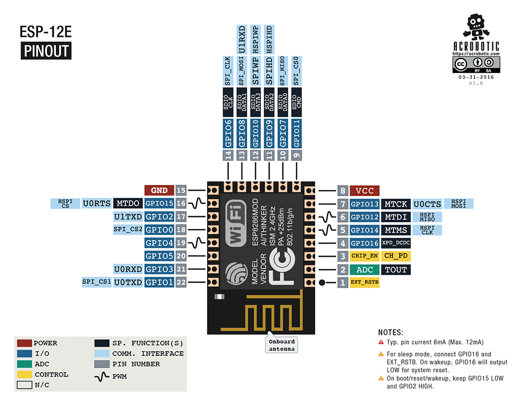
esp8266 pinout
There are a huge number of varieties of the ESP8266 module. The figure shows some of them. The most popular option is ESP 01.

The execution of the program must be determined by the state of the GPIO0, GPIO2 and GPIO15 ports when the power supply ends. Two important modes can be distinguished - when the code is executed from the UART (GPIO0 = 0, GPIO2 = 1 and GPIO15 = 0) for flashing a flash card and when it is executed from an external ROM (GPIO0 = 1, GPIO2 = 1 and GPIO15 = 0) in the standard mode.
The pinout for ESP01 is shown in the picture.


Contact description:
- 1 – ground, 8 – power. According to the documentation, the voltage is supplied up to 3.6 V - this is important to take into account when working with Arduino, which is usually supplied with 5 V.
- 6 – RST, needed to reboot the microcontroller when a low logic level is applied to it.
- 4 – CP_PD, also used to put the device into energy saving mode.
- 7 and 0 – RXD0 and TXD0, this is a hardware UART required for flashing the module.
- 2 – TXD0, an LED is connected to this pin, which lights up when the logic level on GPIO1 is low and when data is transmitted via UART.
- 5 – GPIO0, input and output port, also allows you to put the device into programming mode (when the port is connected to a low logic level and voltage is applied).
- 3 – GPIO2, input and output port.
ESP-12 pinout
The main differences between Arduino and ESP8266
- The ESP8266 has a larger amount of flash memory, while the ESP8266 does not have non-volatile memory;
- ESP8266 processor is faster than Arduino;
- ESP8266 has Wi-Fi;
- ESP8266 consumes more current than Arduino;
Programming ESP8266 in Arduino IDE
The esp8266 development kit includes:
- Compiler from the GNU Compiler Collection.
- Libraries, WiFi, TCP/IP protocol stacks.
- A means of loading information into the controller program.
- Operating IDE.
Initially, ESP8266 modules are supplied with firmware from the manufacturer. With its help, you can control the module from an external microcontroller and work with Wi-Fi as a modem. There are also many other ready-made firmware. Some of them allow you to configure the module’s operation using a WEB interface.
Can be programmed from Arduino environment IDE. With its help, you can easily write sketches and upload them to the ESP8266, flash the ESP8266, and do not require the Arduino board itself. Arduino IDE supports all kinds of ESP8266 modules.
IN present moment The following functions can be implemented for ESP8266:
- Basic functions of the Wiring language. You can control the GPIO ports in the same way as the pins on the Arduino board: pinMode, digitalRead, digitalWrite, analogWrite. The analogRead(A0) command allows you to read ADC values. Using the analogWrite (pin, value) command, you can connect PWM to the desired GPIO output. When value=0 PWM is disabled, maximum value reaches a constant equal to 1023. Using the attachInterrupt and detachInterrupt functions, you can interrupt on any GPIO port except 16.
- Timing and delay. Using the millis and micros commands you can return the ms and μs that have passed since the start. Delay allows you to pause program execution for the desired time. Also, the delay(…) function allows you to maintain normal Wi-Fi work, if the sketch contains large elements that take more than 50 ms to execute. Yield() is an analogue of the delay(0) function.
- Serial and Serial1 (UART0 and UART1). Serial work on ESP8266 is similar to work on Arduino. Writing and reading data blocks code execution if the 128-byte FIFO and 256-byte software buffer are full. The Serial object uses hardware UART0, you can set pins GPIO15 (TX) and GPIO13 (RX) for it instead of GPIO1(TX) and GPIO3(RX). To do this, after the Serial.begin(); you need to call Serial.swap();. Similarly, Serial1 uses UART1, which works for transmission. The required pin for this is GPIO2.
- Macro PROGMEM. Its operation is similar to that of Arduino. Allows you to move read only data and string constants into flash memory. At the same time, the ESP8266 does not store the same constants, which leads to additional waste of flash memory.
- I2C. Before working with the I2C bus, the buses are selected using the Wire.pins(int sda, int scl) function.
- SPI, OneWire – fully supported.
Using esp8266 to communicate with Arduino over WiFi
Before connecting to Arduino, it is important to remember that the supply voltage of the ESP8266 cannot be higher than 3.6, while on the Arduino the voltage is 5 V. You need to connect 2 microcontrollers using resistive dividers. Before connecting the module, you need to familiarize yourself with the pinout of the selected ESP8266. The connection diagram for ESP8266-01 is shown in the figure.
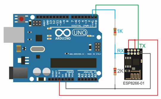
3.3 V from Arduino to Vcc&CH_PD on the ESP8266 module, Ground from Arduino to ground from ESP8266, 0 – TX, 1 – RX.
For support stable operation ESP8266 needs source DC voltage at 3.3 V and maximum current 250 mA. If the power comes from a USB-TTL converter, malfunctions and malfunctions may occur.
Working with the Wi-Fi library for the ESP8266 is similar to the library for a regular shield. There are several features:
- mode(m) – to select one of three modes: client, access point, or both modes at the same time.
- softAP(ssid) – needed to create an open access point.
- softAP(ssid, password) – creates an access point with a password, which must consist of at least 8 characters.
- WiFi.macAddress(mac) and WiFi.softAPmacAddress(mac) – defines the MAC address.
- WiFi.localIP() and WiFi.softAPIP() – determining the IP address.
- printDiag(Serial); – will allow you to find out diagnostic data.
- WiFiUDP – support for sending and receiving multicast packets in client mode.
The work is performed according to the following algorithm:
- Connecting USB-TTL to USB and to ESP.
- Launching Arduino IDE.
- Select the required port, board, frequency and flash memory size in the tools menu.
- File - Examples - ESP8266WiFi - WiFiWebServer.
- Write down the SSID and password of the Wi-Fi network in the sketch.
- Start compiling and uploading code.
- Wait for the firmware process to finish, disconnect GPIO0 from ground.
- Set the speed to 115200.
- A connection will occur and the IP address will be recorded.
- Open the browser, enter address bar IP number/gpio/1
- Look at the port monitor; if an LED is connected to the GPIO2 output, it should light up.
NodeMCU based on esp8266
 NodeMCU is a platform based on the esp8266 module. Used to control the circuit remotely using the Internet via Wi-Fi. The board is small-sized, compact, inexpensive, and has a USB connector on the front side. Nearby are buttons for debugging and rebooting the microcontroller. An ESP8266 chip is also installed. Supply voltage is from 5 to 12 V, it is advisable to supply more than 10 V.
The board's big advantage is its low power consumption. They are often used in self-powered circuits. There are only 11 ports on the board general purpose, some of them have special functions:
- D1 and D2 – for I2C/ TWI interface;
- D5-D8 - for SPI interface;
- D9, D10 – for UART;
- D1-D10 – can work as PWM.
The platform has a modern API for hardware input and output. This allows you to reduce the number of steps when working with equipment and when setting it up. With the help of NodeMCU firmware, you can use the full operational potential for rapid device development.
WeMos based on esp8266
 WeMos is another type of platform based on the esp8266 microcontroller. Accordingly, there is a Wi-Fi module, Arduino IDE is supported, and there is a connector for an external antenna. The board has 11 digital inputs/outputs, which (except D0) support interrupt/pwm/I2C/one-wire. The maximum supply voltage reaches 3.3 V. There is also a USB connector on the platform. Analog input 1 with a maximum voltage of 3.2V.
To work with the module, you need to install the CH340 driver and configure the Arduino IDE for the ESP8266. To do this, you need to add the address http://arduino.esp8266.com/stable/package_esp8266com_index.json in the settings menu in the “additional link for board manager” line.
After this, you need to find the esp8266 by ESP8266 package and install it. Then you need to select the Wemos D1 R2 microcontroller from the tools menu and write down the desired sketch.
Conclusions on ESP8266
With boards based on the ESP8266 chip, you can add capabilities to your projects. big internet”, making them much more intelligent. Remote control, collecting and analyzing data on the server, voice processing and working with images - all this becomes available when we connect our project via WiFi to the Internet. In the following articles, we will take a closer look at how you can program esp8266-based devices, and also pay attention to such popular boards as WeMos and NodeMcu.
Arduino boards and similar microcontrollers make creativity more accessible than ever, they write. Regardless of the purpose of use - to automate your home or control LED strips, or even to protect your property, these amazing little technical devices are the core of most DIY electronic devices.
If you need to command your Arduino to change the position of the pin jumpers (for example, turn on the light), then the Arduino will require the user to press physical button or use a sensor. For many projects, using human finger pressure or similar methods to control devices is fine, but what should you do if you just wanted to build a circuit that could be remotely accessed?
This article gives brief description six ways to connect your Android device to any compatible Arduino board.
1. ArduinoDroid allows you to create sketches
The first device on our list is ArduinoDroid. This application works via USB On The Go (OTG), connecting your mobile device to the Arduino via a USB cable. One of benefits of USB cable means there is no need to connect to the Internet or Bluetooth for the device to function.
The application is a full-featured IDE that allows the user to write code on a smartphone, download previously written sketches that are stored in Dropbox or Google drive and then start the compilation process.

The benefits of using the ArduinoDroid app are obvious. Having an IDE at your fingertips allows you to quickly make changes to fields, and the process of attaching an Android device is less complicated and time-consuming than trying to balance a bulky laptop in your arms!
The obvious disadvantage of the ArduinoDroid application is that writing code on your device may not be a very comfortable experience, especially if you use a smartphone for this purpose. At the same time, this weak point of the application is not so pronounced when on one side of the scale is the convenience of having an ultra-portable method of programming on your board at hand without the need for an Internet connection, and on the other side of the scale is the not very comfortable method of writing code .
On the other hand, having an ArduinoDroid is an inexpensive way to learn Arduino basics, since an Arduino board clone and USB On The Go cost a few dollars. For those who rarely have access to a computer, the ArduinoDroid app is a great alternative!
2. Arduino Bluetooth Controller
The next program on our list is the aptly named Arduino Bluetooth Controller. This application is of great importance in relation to triggers for changes in loaded sketches, and of less importance for Arduino programming. Arduino controller Bluetooth sends data to your board via Bluetooth, giving you the ability to send serial data with the press of a button. You will need bluetooth module for your board, although the module HC-06 widely used and available for as little as $3.
Worthy of mention is the fact that the program is loaded on English, although the Play Store pictures indicate Italian!
3. Blynk application for developing projects
The Blynk application is an excellent development for creating projects. The application's flexibility and simplicity provide an intuitive approach to triggering events on your board. Working with Blynk requires an Internet connection, as the application uses its own own server. You can use either Wi-Fi or mobile data to access the Blynk app, and this feature works great on smartphones.
One of the strongest points of the application is the variability of connections to the device. With support for almost all development boards, you can connect to the server wirelessly, or using ethernet and even a computer via USB. The service is well documented, and its intuitive application makes it easy to integrate customized control over your project. The Blynk library for the Arduino IDE monitors all communications.
If you prefer to turn on your coffee machine using your smartphone before getting out of bed early in the morning, this app is truly for you!
Blynk is not the only service in this category. It is also worth paying attention to such an extremely customized service as Thinger.io and the almost unlimited, albeit extremely difficult OpenHAB. Of the three services, Blynk is the fastest to get up and running, although learning OpenHAB is a great idea in the long run.
4. Communication from scratch
The applications described above assume the use of already existing services, which assist you in providing various connection options. What you need to do to exercise complete and total control over every aspect of your applications Android devices? Why don't you solve this issue yourself and from scratch?
The problem of maintaining control over a package of applications is solved simply by opening USB connection and back-and-forth serial data transfer between applications and the Arduino board. This control option is one of the best to get acquainted with. Android Studio and application creation in general.

It should be noted that if there are methods and methods for creating applications for devices on the Android platform without code, learning the basics of coding is also worth attention software in Java.
5. Turn your Arduino into a server
An alternative way to communicate with your board is to turn it into a tiny server. Key Advantage This transformation of the board into a server is the emergence of the ability to communicate with the boards from any device that can navigate by IP address or send a web request. This will require attachment Ethernet shield to your board to your home network.
If you don't have an Ethernet shield , then a similar effect can be achieved through a Wi-Fi shield or through a board connected to Wi-Fi, like NodeMCU.
If node.js code is your jam, it might make sense to take a look at the arduino-android github project. Once again, we repeat that Android applications are developed based on open source, and all you need to do is install the node.js server on the Arduino board of your choice.

6. Infrared control
If you are looking for a universal communication tool with your Arduino or you would like to play the role of the legendary secret agent MacGyver, then remove infrared receiver(IT) from your old stereo or VHS player and use it to communicate with your Arduino board!
Would you like to send text message from your Android smartphone to your Arduino board? This article tells you how to do it!
What you need
- Android smartphone supporting USB host mode (i.e. OTG support) - most devices running Android 3.1 and higher support this mode. Test your phone using the USB Host Diagnostics App from the Play Store;
- Arduino - any version. I'll be using Uno R3;
- USB cable for Arduino;
- USB OTG cable- you need it to connect the Arduino USB cable to micro-USB port telephone;
- Android Studio - you need to install it. It's quite easy to do. Android Studio makes app development easier with its assumptions and code generation. This is one of best IDEs. You can also use this article as a guide to Android installation IDE.
Basic components of an Android application
There are three main files in an Android application:
MainActivity.java This is where the executable Java code is located that controls how the application will function. activity_main.xml Contains the application layout, that is, components: buttons, text display components, etc. AndroidManifest.xml Here you define when the application should run, what permissions it needs, and what hardware it needs to access.
There are many more files, but they are all connected to each other using these three.
An activity can be characterized as a screen where the user interacts with the phone. Activities contain widgets such as buttons, text fields, images, etc. that help in conveying information. This tutorial will only use one activity, MainActivity, which will accept user input to send to the Arduino and also display the received text.
Layout

We will use the same layout as the USB App and Bluetooth App. It is simple and contains the minimum widgets needed to test the connection between devices.
As you can see, it contains an EditText widget to receive data from the user, buttons to start the connection, transfer data, end the connection, and clear the TextView . The received data is displayed in a TextView (empty space below the buttons).
Here is part of the XML code. Because the code for the buttons is similar, it is not shown here. The full code can be downloaded from the link at the end of the article.
I've used a RelativeLayout here, which means that each widget is positioned relative to the widgets around it. The layout can be easily recreated in the Design Tab, where you can drag and drop widgets wherever you want. We need to describe what will happen when the button is pressed. The onClick method is used for this. Specify the method name in the XML code for the button. To do this, add the line:
Android:onClick="onClickMethod"
Now hover your mouse over this line and a warning similar to this should appear on the left:

Click on the “Create onClick...” option. This will automatically add the onClick method code to MainActivity.java. You need to do this for each button.
USB Serial Library
Settings serial connection in Android is quite labor-intensive, as it requires you manual settings a lot of things, so I found several libraries that do it all automatically. I tested several of them and finally settled on the UsbSerial library from Github user felHR85. Among similar libraries that I found, it is the only one that is still updated. It's quite easy to set up and use. To add the library to your project, download the latest JAR file from Github. Place it in the libs subdirectory of your project directory. Then, in the file explorer in Android Studio, right-click on the JAR file and select “Add as Library”. That's it!
Program execution algorithm

This is a short outline of how we will proceed. Every activity has an onCreate() method, which runs when the activity is created. Whatever code you want to run at the beginning should be placed inside this method. Please note that reading from the device is asynchronous, meaning it will work in the background. This is done to ensure that the data is received as quickly as possible.
Opening a connection
First, let's define an onClick method for the Begin button. When clicked, you need to search for all connected devices and then check if the VendorID of the connected device (vendor ID) is the same as the VendorID of the Arduino. If a match is found, the user must be asked for permission. Each USB slave device has a Vendor ID and a Product ID, which can be used to determine which drivers should be used for that device. Vendor ID for any Arduino board is 0x2341 or 9025.
Public void onClickStart(View view) ( HashMap usbDevices = usbManager.getDeviceList(); if (!usbDevices.isEmpty()) ( boolean keep = true; for (Map.Entry entry: usbDevices.entrySet()) ( device = entry. getValue(); int deviceVID = device.getVendorId(); if (deviceVID == 0x2341) //Arduino Vendor ID ( PendingIntent pi = PendingIntent.getBroadcast(this, 0, new Intent(ACTION_USB_PERMISSION), 0); usbManager.requestPermission( device, pi); keep = false; ) else ( connection = null; device = null; ) if (!keep) break ;
Now let's define a BroadcastReceiver to receive broadcast messages to ask the user for permissions and also to automatic start connection when the device is connected, and closing the connection when it is disconnected.
// Broadcast message receiver to automatically start and close a serial connection. private final BroadcastReceiver broadcastReceiver = new BroadcastReceiver() ( @Override public void onReceive(Context context, Intent intent) ( if (intent.getAction().equals(ACTION_USB_PERMISSION)) ( boolean granted = intent.getExtras().getBoolean(UsbManager. EXTRA_PERMISSION_GRANTED); if (granted) ( connection = usbManager.openDevice(device); serialPort = UsbSerialDevice.createUsbSerialDevice(device, connection); if (serialPort != null) ( if (serialPort.open()) ( //Set serial parameters connections. setUiEnabled(true); //Enable buttons in UI. serialPort.setDataBits(UsbSerialInterface.DATA_BITS_8); serialPort.setStopBits(UsbSerialInterface.STOP_BITS_1); rt. setFlowControl(UsbSerialInterface.FLOW_CONTROL_OFF); serialPort.read(mCallback); // tvAppend(textView,"Serial Connection Opened!\n"); else ( Log.d("SERIAL", "PORT NOT OPEN"); ) ) else ( Log.d("SERIAL", "PORT IS NULL"); ) ) else ( Log.d("SERIAL", "PERM NOT GRANTED"); ) ) else if (intent.getAction().equals(UsbManager.ACTION_USB_DEVICE_ATTACHED)) ( onClickStart(startButton); ) else if (intent.getAction ().equals(UsbManager.ACTION_USB_DEVICE_DETACHED)) ( onClickStop(stopButton); ) ); );
If the first IF condition is met, and if the user has given permission, then start connecting to the device whose Vendor ID matches the Vendor ID we need. Additionally, if a broadcast message is received about connecting or disconnecting a device, manually call the onClick methods on the Start and Stop buttons. SerialPort is defined using device and connection as arguments. If successful, open SerialPort and set the appropriate parameters. The parameter values for Arduino Uno are: 8 data bits, 1 stop bit, no parity bit, flow control disabled. The baud rate can be 300, 600, 1200, 2400, 4800, 9600, 14400, 19200, 28800, 38400, 57600 or 115200 bps, but we will use the standard 9600 bps.
Receiving data from the device
In the code snippet above, notice the line containing serialPort.read(mCallback) . Here, the read function is passed a reference to a Callback object, which will automatically fire when incoming data is detected.
UsbSerialInterface.UsbReadCallback mCallback = new UsbSerialInterface.UsbReadCallback() ( // Define a callback method that is called when data is received. @Override public void onReceivedData(byte arg0) ( String data = null; try ( data = new String(arg0, " UTF-8"); data.concat("/n"); tvAppend(textView, data); ) catch (UnsupportedEncodingException e) ( e.printStackTrace(); ) ) );
The received data will be in the form of raw bytes. We'll have to recode them to readable format eg UTF-8. They are then added to the TextView using the special tvAppend() method. This is done this way because any changes to the user interface can only be done on the thread user interface. Since this Callback will be run as a background thread, it cannot directly affect the user interface.
Private void tvAppend(TextView tv, CharSequence text) ( final TextView ftv = tv; final CharSequence ftext = text; runOnUiThread(new Runnable() ( @Override public void run() ( ftv.append(ftext); ) )); )
Transferring data to the device
Transferring data is relatively simple compared to reading data from a device. This is a simple function call with the bytes of data to be passed as an argument. This will be implemented in the onClick method of the Send button.
SerialPort.write(string.getBytes());
Closing a connection
To close a connection, simply close serial port.
SerialPort.close();
Application manifest
The manifest declares what additional permissions the application may require. The only permission we need is permission to make the phone a USB host. Add the following line to your manifest:
You can force your app to start automatically by adding an intent filter to your main activity, MainActivity . This intent filter will be triggered when any new device is connected. The device type can be specified explicitly using the Vendor ID and/or Product ID in the XML file.
Notice the line " android:resource="@xml/device_filter ". This tells the compiler that it can find the device properties in a file called device_filter in the src/main/res/xml directory, so create a subdirectory " xml " in the src directory /main/res and place a file with the following content in it:
Application testing
Build the application and run it on your smartphone. Now launch the Arduino IDE and configure the Arduino to simply echo whatever the board will accept via the serial port. Here's some very simple code to help you do this:
Void setup() ( Serial.begin(9600); ) void loop() ( char c; if(Serial.available()) ( c = Serial.read(); Serial.print(c); ) )
Now connect the Arduino to the microUSB port of your phone using an OTG cable. The application should launch automatically. Try sending some text and the same data will be returned!

Conclusion
This article shows how Arduino can communicate with your smartphone. And the possibilities for using it are endless! In the case when data is needed from any sensor that is not among those built into the smartphone, you can use any microcontroller to read data from this sensor and transfer it to the smartphone. The next article will show you how to connect your smartphone to Arduino using the popular HC05 bluetooth module.
Machine on arduino and Bluetooth without editing the code. We will use specialized free software to create the sketch. In addition, you don’t need to buy a chassis for our craft; almost any faulty radio-controlled model of a car or tank will do.
I suggest watching an overview video about the Bluetooth-controlled machine and its contents.
So, let's look at a live example of how to make a machine with your own hands, remotely controlled via bluetooth from an Android tablet or smartphone. The article, oddly enough, is intended for an initial level of knowledge. There is no guide to editing code in the Arduino IDE, and we will only use it to fill in our code. And we will compose the control algorithm in a program called FLProg. Control program from a smartphone - HmiKaskada_free. But first, about the hardware we need.
Machine on arduino and Bluetooth - hardware.
The first thing you need is chassis, that is, a body with wheels and motors, which will drive for the joy of us and those around us. In my case, I used a case from a radio-controlled toy in which the power part burned out. The prospect of renovation seemed dull to me, and I wanted something new for my children. That's how this project was born. The body contains two engines that drive the wheels on the sides of the machine, like a tank. All electronic components were sent for spare parts.
To control the electric motors of our future creation we will need H-bridge on L298N chip Link to Ali, I took this one from. The picture is clickable.
H-bridge for arduino
Can control two motors in the voltage range 5 - 35 volts. Supports PWM, that is, you can adjust the engine speed. The board has a stabilized voltage output of 5 volts to power the Arduino.
The connection diagram is simple and unpretentious:

The next integral part of the electronic filling of our project is bluetooth module HC-06. The most common module for Arduino, so popular that in additional description doesn't need it.

HC-06 bluetooth for arduino
The main element and brain in my case is arduino nano, I won’t even post a photo here because everyone knows about it and knows how to work with it. By the way, any Arduino board will do, as long as it fits in the case 😀
Batteries and soldering wires do not require specification. The choice of batteries depends on the operating voltage of the electric motors.
Machine on arduino and Bluetooth - drawing up a sketch.
I repeat - there will be no digging in the code here. We will use popular program FLProg. You can download its latest version on the official website. The program's interface is simple and unpretentious, but it has enormous functionality and support for almost all popular modules. I won’t write how to use it because it would take a couple of articles. Let me just say that I have never met a more convenient and available program for making sketches for arduino and its clones. Interface screen:

FLProg interface
The site is full of text and video manuals, I think you’ll figure it out.
My project for a remote-controlled car can be downloaded from Yandex disk via the link shortening service.
Machine on arduino and Bluetooth - control interface on an Android tablet.
Due to numerous requests, I wrote detailed instructions for developing a control interface based on HmiKaskada android in the article. The link is clickable.
For devices running Android there is a program HmiKaskada (link to YandexDisk). It was initially developed as an alternative to expensive industrial HMI panels. But inquisitive minds quickly realized that she could control anything. In our case, a typewriter. Supports wireless interfaces Wi-Fi and Bluetooth, in addition, you can connect the device directly via USB.
There are paid and free versions of the program. I have both, but I basically made the project in the free version to show you and once again make sure that the free version is absolutely functional. The main difference between free and PRO versions is that it works only via Bluetooth.
There is a giant thread on the FLProg forum regarding compatibility with KaScada, and the developer is active and sociable. I don’t see any point in posting a screenshot of the control panel - it’s in the video.