What cable length is allowed for a homemade 3g antenna. Calculation of the Kharchenko antenna (zigzag)
I have another proven option antennas under 3g modem Ukrainian operator Intertelecom.
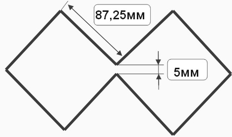
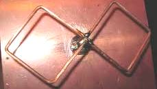
The Kharchenko antenna, as it is also called (aka bi-square), has the form of two squares of 87.25 mm each. on each side of the square bent at an angle of 90 degrees. Copper core 4mm thick. and length 698mm. divide into 8 even parts and bend as shown here:
The calculation could have been done with a special program, but I decided the old fashioned way, with a calculator.
I took the average operating frequency of the modem - 850 MHz +/- 50 MHz. I made these conclusions from the fact that in the online store where I bought the modem itself, they offered me an antenna with a frequency of 800 MHz. with gain 25dBm. So I decided to assemble an antenna using these numbers in two evenings. And I’ll tell you that the antenna turned out quite normal.
We calculate the wavelength by dividing the speed of propagation of radio waves (300,000 km/sec) by the frequency: 300,000 / 860,000 = 0.349 m. The perimeter of the frame should be equal to length waves, that is, 349 mm., then the side of the square will be: 349 / 4 = 87.25 mm. Many sources give sides of different lengths - from 27 to 53 mm... . Obviously, such antennas are designed for a different frequency range (GSM or Wi-Fi, or completely unknown to me) and will work well only in this range.
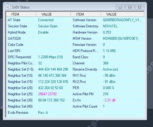
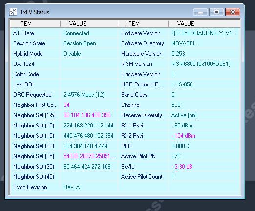
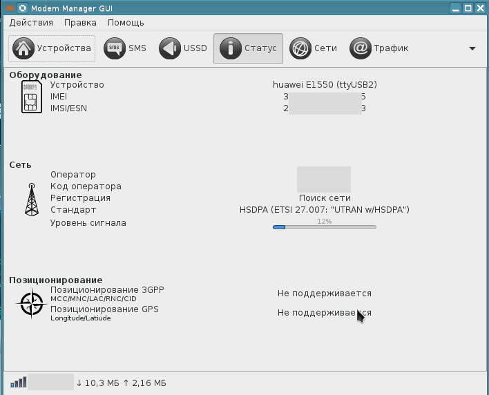
Screenshot of the program with readings without:
And with antenna:
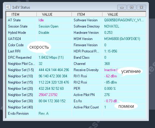
As you can see from the readings, my Internet speed is not so great today (the operator is a tight-fist), but the gain has increased significantly and there is less interference. Or maybe you need to run around on the roof, find a suitable place, during the day I measured the speed, it was much higher.
Now a little about the reflector. The reflector can be made from any metal plate or even from a mesh/grid with small cells. You can also take, for example, plywood or thick cardboard and stick foil on it. The distance from the reflector to the antenna is also important; for example, the input impedance depends on it. Theoretically (from other sources) this distance should be a quarter of the wavelength, in our case: 349 / 4 = 87.25 mm. But for me personally it works well at a distance of 40mm.
And also, I took a coaxial cable with a resistance of 75 Ohms, 10 m long.
Updated the next day:
As I said, you just need to run around the roof to look for the most stable place for best quality communications. I twisted it left and right until I found the right position. I secured it securely because tilting it in any direction causes the signal to get lost.
Here is proof of this, the signal increased to 2.4576 Mbps.
That's it, it seems.
Good luck.
Considering the features of the Kharchenko antenna, you and I, dear anonymous, noted that in the West this antenna is called “Trevor Marshall's antenna” in honor of the one who was one of the first in 2001 to propose its use in networks WiFi. The director of the Center for Autoimmune Diseases, Professor Trevor Marshall (USA), is also a qualified amateur radio operator. On his personal website you can find a description of this very design, which he used as a feed for a mirror antenna. Let's look at it and recalculate for 3G-4G networks...
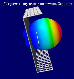 Marshall used a 110x110mm reflector. However, he notes that if the antenna will be used independently, and not as a dish feed, then it is better to make the reflector with sides 123x123 mm, i.e. equal to length Wi-Fi range waves. At the edges of the reflector there are “jaws” 30 mm high, which reduce the back and side lobes of the antenna radiation pattern by approximately 6 dB. The antenna was calculated in the 4NEC2 program, the model file for this program can be downloaded from us. A general 3D view of the radiation pattern for the Bi-Quad antenna that the 4NEC2 produces can be seen in the figure. In the author's article, a tube is soldered behind the reflector, which serves solely as a fastening element and does not perform any special function. The author notes that if the structure is assembled carefully, then balancing devices are not required. Marshall suggests using 1.2mm wire. Participated in testing the antenna large number radio amateurs from different countries and came to the conclusion that the wire diameter needed to be larger to cover the entire Wi-Fi range. The analysis shows that with an increase in diameter from 1.2 to 1.6 mm, the SWR at the center frequency increases from 1.14 to 1.22, which is insignificant, and the antenna gain decreases by 1 dB, which is also not much. In this case, the antenna covers all 14 Wi-Fi channels.
The estimated antenna gain is about 10 dBi, input impedance is 50 Ohms. Based on the NEC model, we created online calculator, with which you can recalculate the dimensions of the antenna for other frequencies. Schematic representation of the antenna: 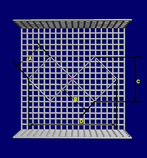
Since the advent of radio communications, the issue of using an antenna has been very relevant. In 1961, engineer Kharchenko proposed a design consisting of two rhombuses. With its help, he caught American broadcasts.
Evolution
The antenna, invented by Kharchenko, is a double square made of thick copper wire. The squares are connected to each other with open corners, and at this point the television cable is connected to them. To improve directionality, a grille made of conductive material is installed at the rear.
The perimeter of each square is equal to the wavelength to which the reception is tuned. Wire diameter for 1-5 television channels should be about 12 cm. Because of this, for radio communications and meter range television (channels 1-12) it turns out to be very cumbersome. To facilitate the design, a gasket with three wires of a smaller cross-section was used, but it still had a lot of weight and dimensions.
The zigzag antenna created by Kharchenko received a second life when broadcasting in the UHF range. Everyone remembers rhombuses, circles, triangles and other homemade figures as a TV antenna for receiving decimeter waves, which hung on many people’s balconies and outside their windows. They were one of the signs of that time.
In 2001, Professor Trevor Marshall (USA) proposed using this design in Bluetooth networks and WiFi.
This article talks about what devices are available for these purposes and how to make such an antenna with your own hands.
One drawing can be used zigzag antenna for all ranges. The only differences are in size.
Antennas for TV
There is practically no meter-wave television, and Kharchenko’s zigzag antenna was not used to receive these channels due to its large dimensions. Therefore, this article only talks about its application for UHF and DVB-T2.
Improving UHF reception
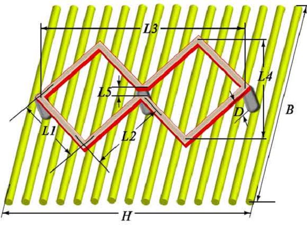
For UHF reception, the zigzag antenna has the following dimensions:
- L1 (outer side of the square) – 141.8 mm;
- L2 ( inner side square) – 135.6 mm;
- L3 (frame length) – 397.4 mm;
- L4 (frame width) – 198.7 mm;
- L5 (connection gap) – 8.4 mm;
- D (height of racks) – 65 mm;
- B (screen width) – 565 mm;
- H (screen length) – 565 mm;
- wire diameter – 9.6 mm;
- quantity of wire – 1166.9 mm.
It turns out to be quite broadband and does not require additional settings. Connects with a piece TV cable. Characteristic impedance - about 50 Ohms. The antenna matches well with coaxial cable with resistance of both 50 and 75 Ohms. To improve broadband, it can be made not from wire, but from copper or aluminum strip and connected with rivets. The copper strip can be additionally soldered. The length of the strip is calculated between the rivet holes.
If you use antenna amplifier, then the second square is not needed, you can take only one.
Improved T2 reception
Digital TV DVB-T2 is broadcast at UHF frequencies on channels 21-69 using the multiplex method. Therefore, the design for T2 needs the same dimensions as the antenna for digital television DCV range. However modern televisions if the signal is too strong, it is blocked. Therefore, if the transmitter for T2 is too close, and you want to use the old frame for DVB-T2, then you may need a weaker amplifier for digital television, you will have to cut off one square or remove the screen from reverse side. You can also make such a device for t2 with your own hands or use a digital TV antenna made in the form of a circle, 555 mm long. This is enough for digital TV.
Designs for the Internet, 3g and mobile communications
For mobile communications, Bluetooth, 3g and WiFi are used so short waves and high frequencies that the entire device is about 10 cm long and is manufactured according to one drawing for all ranges. The only differences are in the sizes, which can be calculated using an online calculator. You can also use it for your mobile phone.
DIY zigzag antenna
Making an antenna yourself is not difficult. For production you need:
- single-core copper wire;
- soldering iron;
- pliers;
- ruler;
- coaxial cable with wave impedance 50 Ohm;
- conductive material for the screen (foil getinaks, DVD or CD disc, sprat can, etc.);
- a stand that provides the correct distance between the antenna and the screen, for example, a plastic bottle cap;
- glue.
The manufacturing process can be divided into several stages:
- Clean the wire from insulation;
- Using a ruler, mark the folds;
- Use pliers to bend the wire in the previously marked places. The more accurately the markings were made and the wire was bent, the better the reception will be;
- The cable connection points are tinned;
- The cable is tinned, or a plug is put on the cable, to which pieces of wire 10-15 mm long are soldered;
- The wire is soldered to the antenna;
- A stand and a screen are sequentially placed on the cable;
- The entire structure is glued, for example, with silicone.
Improved WiFi and Bluetooth reception
WiFi is transmitted like other types wireless communication, radio waves. Therefore, to improve the performance of a WiFi router or other devices, you can also use this design. According to reviews, if you use a parabolic plate as a screen (alternatively, you can bend it out of a tin can), the gain reaches 31 dB. When using a homemade reflector, its curvature is selected experimentally. To do this, on the device to which the signal is transmitted, you need to install a program that shows the signal level and, changing the curvature of the screen, monitor it.
The calculation is made at a frequency of 2445 MHz.
- L1 (outer side of the square) – 30.8 mm;
- L2 (inner side of the square) – 29.6 mm;
- L3 (frame length) – 84 mm;
- L4 (frame width) – 43 mm;
- L5 (connection gap) – 1.9 mm;
- D (height of racks) – 13.6 mm;
- B (screen width) – 122 mm;
- H (screen length) – 122 mm;
- wire diameter – 2.5 mm;
- quantity of wire – 256.6mm.
Important! The more accurately the dimensions are maintained, the better the reception will be.
You can use a piece of foil getinax as a screen to printed circuit boards. For mechanical strength, the screen is soldered to the wire braid.
You can use a CD or DVD disc. The disk has a thin layer of foil on which information is recorded. In this case, you can make an antenna in a CD box.
Install the Kharchenko antenna horizontally. This is due to the polarization of the signal.
Bluetooth uses the same frequencies as WiFi. Therefore, you need a WiFi range antenna of the same size.
Connecting to a router
If the router has a connector for connecting external antenna, then a plug is soldered to the end of the cable and inserted into the connector.
If it is not there, then to connect you need to open the modem and solder the cable to the board. The shorter the wire, the better. The power of the router is small, and losses in the cable are sometimes decisive.
Attention! This work can only be performed by experienced specialists. Opening the device will void the warranty.
Connecting to a laptop
IN WiFi laptops built-in boards for mobility and reduced size. Therefore, there is no external antenna, and the internal one is low-power. To connect to it, you need to disassemble the laptop and know exactly where it is located. But there is alternative option With using USB WiFi adapter with antenna. Having cut it, you can find the central core and screen. A coaxial cable is respectively soldered to them. Ideal option will be installed directly on the adapter in order to reduce cable losses.
Improved 3g reception
Modern mobile internet uses the 3g standard with a signal frequency of 2100 MHz and a wavelength of 143 mm. Therefore, the dimensions will be as follows:
- L1 (outer side of the square) – 37.1 mm;
- L2 (inner side of the square) – 35.5 mm;
- L3 (frame length) – 104 mm;
- L4 (frame width) – 52 mm;
- L5 (connection gap) – 2.2 mm;
- D (height of racks) – 17 mm;
- B (screen width) – 148 mm;
- H (screen length) – 148 mm;
- wire diameter – 2.5 mm;
- quantity of wire – 305.4 mm.
Structurally, the 3g antenna is no different from the design for WiFi.
Connecting to a 3g modem
The most effective way is to connect the cable inside the router, but to do this you need to be a specialist in the field of repairing mobile communication equipment. For everyone else, we can suggest another method.
Wireless connection
To do this, cut two pieces of copper or brass foil, 45 and 27 mm wide and long enough to wrap the modem and solder the edges. We do the same with a wide section, solder the central core of the cable to it and put it on the modem. Instead of a wide piece of foil, you can strip 15-20 cm of wire and wrap the modem tightly. A narrow piece is bent in a semicircle and soldered to the cable braid. The relative position for the best reception is selected experimentally.
Additional information. If the antenna is connected directly to the modem, without a cable, and the modem itself is connected using a USB extension cable, then losses in the cable can be avoided.
Connect to a smartphone or tablet
It is necessary to strip a piece of cable and wrap the central conductor 10-15 turns around the phone. You can also take a piece of brass or copper foil, solder the central core of the cable to it and insert it between back cover and a cover.
Improved 4g reception
Mobile Internet of the 4g standard uses a frequency of 2600 MHz with a wavelength of 115 mm. Therefore, the dimensions will be:
- L1 (outer side of the square) – 28.9 mm;
- L2 (inner side of the square) – 27.6 mm;
- L3 (frame length) – 81 mm;
- L4 (frame width) – 40.5 mm;
- L5 (connection gap) – 1.7 mm;
- D (height of racks) – 13.2 mm;
- B (screen width) – 115 mm;
- H (screen length) – 115 mm;
- wire diameter – 2 mm;
- quantity of wire – 237.9 mm.
Cell phone antenna
Mobile communications operate in two bands. You can find out which one you need on your operator’s website.
Comparative characteristics
| Options | GSM 900 | GSM 1800 |
|---|---|---|
| L1 (outer side of square) | 81.2 mm | 41.9 mm |
| L2 (inner side of square) | 77.7 mm | 40 mm |
| L3 (frame length) | 227.7 mm | 117.3 mm |
| L4 (frame width) | 113.8 mm | 58.7 mm |
| L5 (connection gap) | 4.8 mm | 2.5 mm |
| D (rack height) | 37.2 mm | 19.2 mm |
| B (screen width) | 324 mm | 167 mm |
| H (screen length) | 324 mm | 167 mm |
| Wire diameter | 5.5 mm | 2.9 mm |
| Wire length | 668.6 mm | 344.5 mm |
"Double" Bi-Quad (double biquad)
Double biquadrat is also a Kharchenko antenna. It is made with your own hands in the same way as a regular biquadrat. It differs from a regular biquadrat in that at the vertices of the squares, instead of the corners, there are additional squares. The dimensions of these squares are exactly the same as the main ones. Therefore, no additional calculation is needed; you can take the calculation for a regular biquadrat. The calculation for the Kharchenko antenna can be found in this article or use the online calculator program for the calculation. The wires at the intersection are insulated from each other.
The double biquadrat can be continued in the same way. Those who want to make it can easily calculate the length of the wire. This gives additional gain.
Using small homemade directional antennas, you can receive a signal at a distance of up to 2 kilometers. These homemade products are a good replacement for expensive solutions.
Video
Sometimes I have to travel far out of town and stay there for several days. Yes, I’ve finally decided to move closer to nature by the fall. It’s not that you want the Internet, you just need it for work. 3G network coverage in remote areas of our region is gradually improving, but it is still very far from ideal, like China. The built-in antennas of USB “whistles” work categorically unsatisfactorily. That’s why I started “collective farming” out of habit...
Brief overview of the 3G situation
The vast majority of ready-made 3G devices only work with their built-in antenna and do not have any ability to connect an external antenna. Those that have one, firstly, you won’t be able to turn it up during the day with a fire in the evening, and secondly, this connection is in the vast majority of cases unreliable and has poor characteristics in terms of attenuation/reflection of the signal and the introduction of additional noise. The name pigtail, adopted in relation to such adapter cables, very accurately describes this situation.The quality of the built-in antennas is acceptable for an urban environment, where BSKs are stuck together every step of the way. For camping conditions, such a conditionally omnidirectional super-shortened antenna is completely unsuitable.
However, many 3G modems, even if they do not have a visible connector for connecting an external antenna, have a connection point for the antenna on their board, apparently for diagnostic purposes. Often the connector is even unsoldered at this point.
Thus, it is impossible to do without “surgical intervention”.
There are big pictures under the cut.
“Surgical intervention” in a 3G modem
The modem can be anything. My choice fell on the Huawei E1550, because this old thing turned up to me from a gopnik in the alley, now you can buy it second-hand for 100 rubles - you don’t mind spoiling it. Details of its modification are perfectly available on the Internet of any popular search engine. [for example]In general, you need:
- remove or disable the built-in antenna
- find the diagnostic connection point; if the connector is already soldered on it, remove it (it works well with a hairdryer)
- solder a piece of a suitable one to it coaxial cable, not forgetting that this is still a microwave (the braid is soldered at two points on either side of the central core, the configuration of the contacts on the board provides for this).
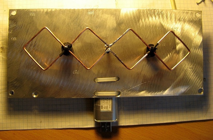
This is what I got (photo against the background of the reflector of the antenna described below):
In addition to everything else, the modem was "unlocked" so that it was possible to test different operators.
Why Kharchenko antenna?
The dipole or GP is rather weak here. The wave channel and log-periodic channel, in addition to the complexity of manual manufacturing at such frequencies and, as a consequence, “fragility,” have a very narrow main lobe of the radiation pattern. IN hiking conditions accurately “aim” at base station(BS) and it is very difficult to securely fix such an antenna.A compromise was found in the form of the Kharchenko zigzag antenna (which I mentioned - now it’s time to try it). Its main lobe of the diagram is wide enough so that it is not very difficult to target the BS, while the antenna is quite simple to manufacture and has a relatively good gain (6..9dB).
Antenna modification
Kharchenko’s antenna is quite broadband, but at the same time, the transmission frequency groups “from MT to BS” (1885..2025 MHz) and “from BS to MT” (2110..2200 MHz) in the UMTS standard are spaced quite far apart. As I already mentioned in the comments to the previous article, the BS almost always has enough power to “shout” to the mobile terminal, but the mobile terminal (MT) does not have enough power (especially the USB “whistle”). You can, of course, make an antenna that works optimally in the group of transmission frequencies “from MT to BS” and be content with average lousy reception, but I wanted to get the most out of this technology.I learned that the Kharchenko antenna can be made even more broadband by turning on several antenna vibrators in parallel in the same plane at the “feeding” point. However, the calculated dimensions of these vibrators for UMTS frequency groups in the “short arm” part differed by less than half a millimeter with the required conductor width of 0.8-0.9 mm. That is, it did not seem possible to me to spread the “short arms” while maintaining the plane of the vibrator.
And I decided: I’ll do it “outside the rules” and see what happens. Hence some negligence in the manufacture of the first versions of the antenna: I simply did not believe that it would “take off.”
The first version of the vibrator drawn on paper looked like this:
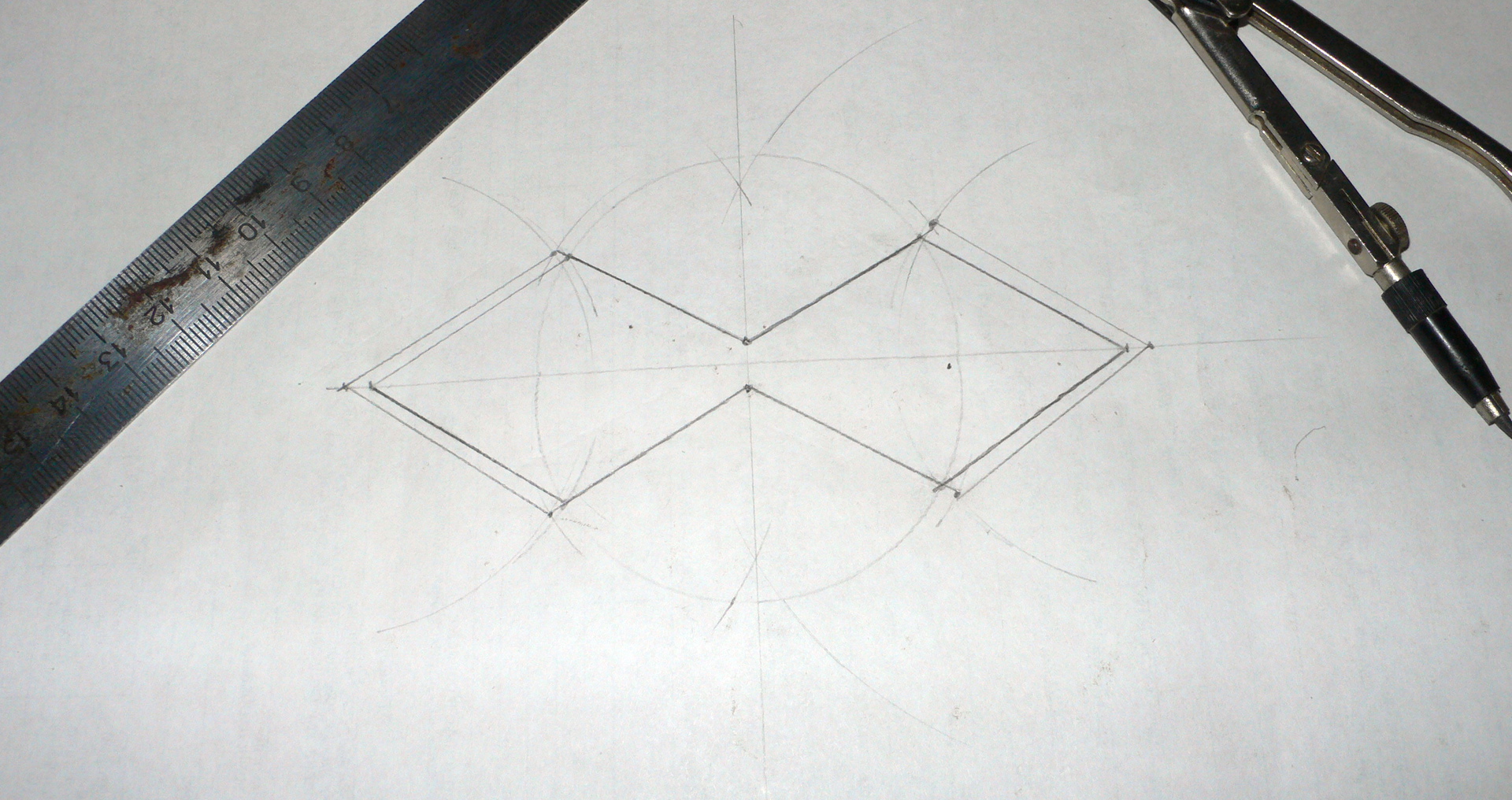
For the “small” circuit, the central frequency was chosen to be 2145 MHz, for the “large” circuit - 2010 MHz.
Calculation data
- Center frequency f: 2010 MHz
Bandwidth at SWR< 1.5: 126 МГц
Bandwidth at SWR< 2: 234 МГц
- Wavelength λ: 149.25 mm
Size L1 (outer side of square): 38.5 mm
Size L2 (inner side of square): 34.3 mm
Size L3 (vibrator length): 125mm
Size L4 (gap at connection point): 7.7 mm
Dimension B (reflector width): 85 mm
Dimension H (reflector length): 146 mm
Wire diameter: 0.9mm
Total wire length: 303mm
Vibrator-reflector distance D: 23.1 mm
Extreme angle of the diamond α: 65°
Kharchenko antenna (zigzag)
- Center frequency f: 2145 MHz
Antenna characteristic impedance ρ: 50 Ohm
Bandwidth at SWR< 1.5: 134 МГц
Bandwidth at SWR< 2: 250 МГц
- Wavelength λ: 139.86 mm
Size L1 (outside square): 36.1 mm
Size L2 (inner side of square): 32.1 mm
Size L3 (vibrator length): 117.2 mm
Size L4 (gap at connection point): 7.2 mm
Dimension B (reflector width): 80 mm
Dimension H (reflector length): 137 mm
Wire diameter: 0.8mm
Total wire length: 283mm
Vibrator-reflector distance D: 21.7 mm
Extreme angle of the diamond α: 65°
It was decided to make the vibrator from available foil-coated fiberglass laminate, followed by extensive tinning.
Making a trial version
The construction of the antenna vibrator circuits was repeated on the textolite: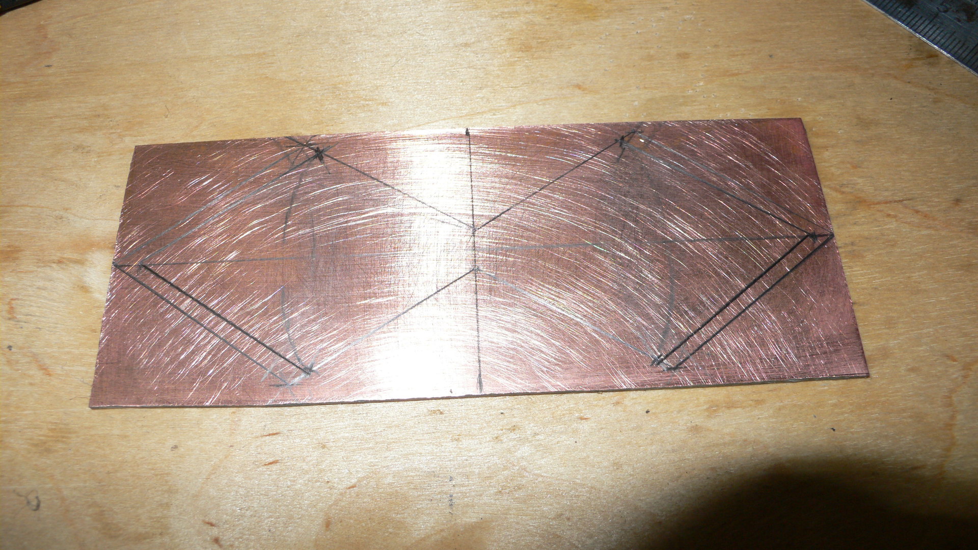
This will cause holy horror in many students:
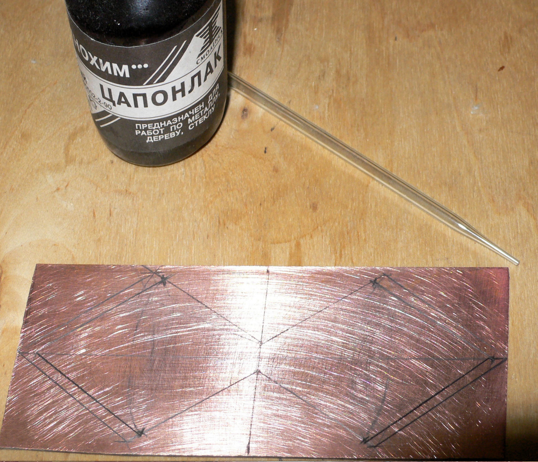
However, I also haven’t worked with a glass drawing pen for a long time, so I’ll omit the intermediate stages:
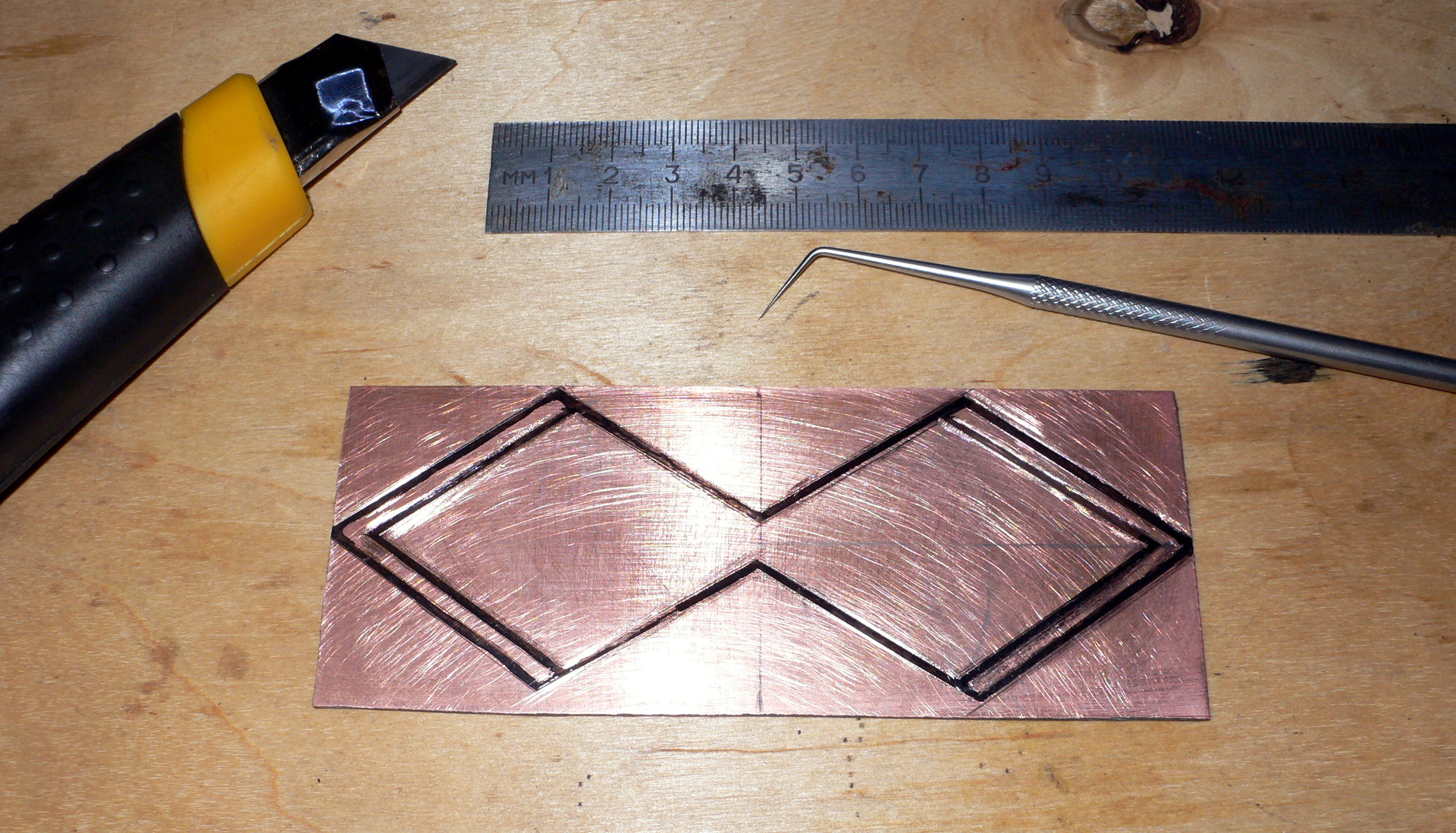
In general, of course, you can do this even with the famous Edding 404 felt-tip pen if you have the skill, but for some reason I wanted to do it this way, the old-fashioned way, with a warm lamp tsaponlak.
For the first time I tried the method of etching copper in a solution of the composition “Citric acid + Table salt + Hydrogen peroxide”. At first there were difficulties associated with low-quality (damp) hydroperite. I realized what the problem was by throwing a couple of tablets from a new pack into the solution (damp hydroperite tablets are swollen, crumbly, grainy - they are of no use; kosher tablets are dense, have clear shapes and do not crumble in the hands). Copper is etched really quickly, accurately and extremely cheaply.
Now I’m wondering what to do with several kilograms of ferric chloride, which I once bought “in reserve”...

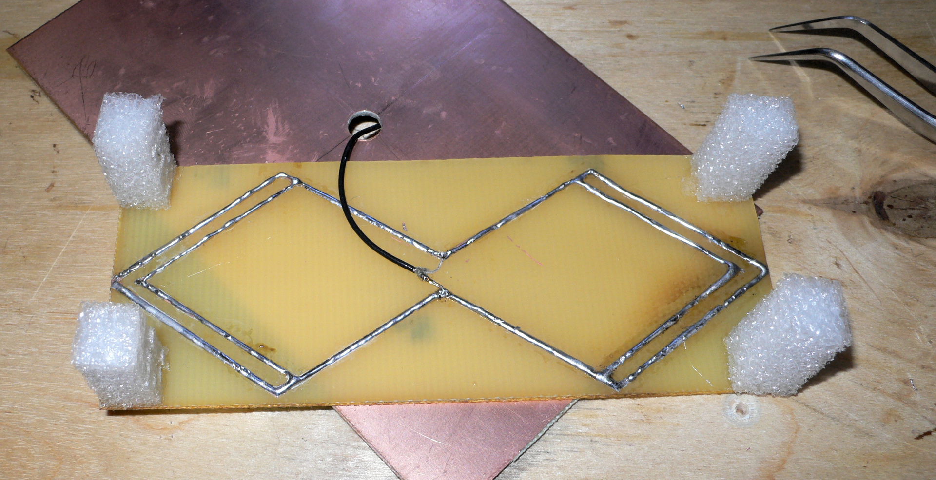
Ready vibrator after tinning:

I solder it. Yes, yes, the legs are made of soft foam. I repeat: I did not believe that it would “take off” and left room for maneuver in the form of an “adjustable” distance between the vibrator and the reflector.
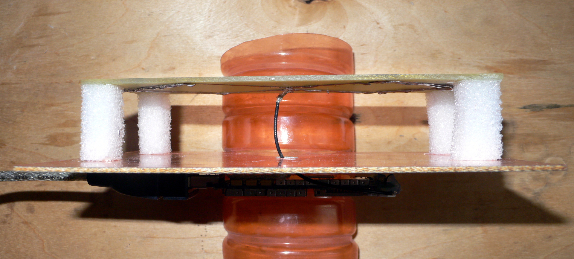
Assembled. The USB connector is stuck to the reflector with double-sided tape. The reflector is inserted into the slot of half a plastic bottle - so that you can stand without your hands.
Trial test results
Almost threw everything in the trash without sorting it out
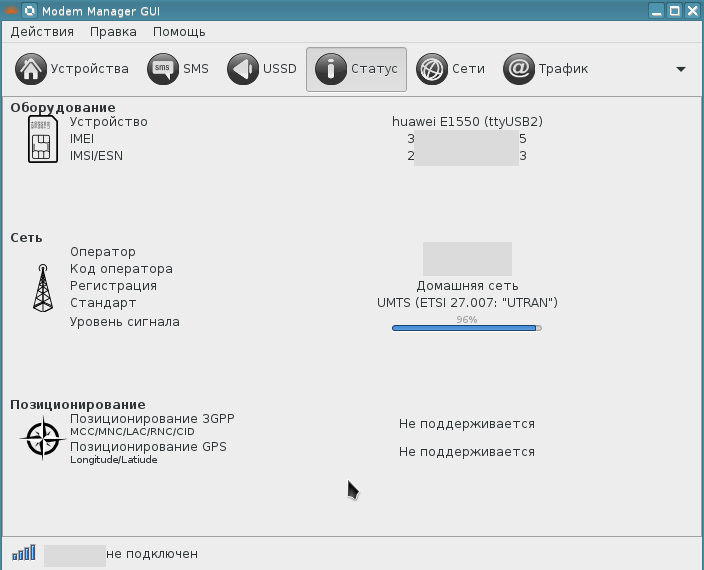
When I plugged the modem into the USB port, with the expected regret I saw “two green whistles” (owners of such devices will understand). That's it, I think the modem is kaput (“kaput” - “spoiled”, “broken” in German). But just in case, I launched minicom and entered “AT+CSQ” (should show RSSI in parrots). Expected zeros. But the modem responded: “+CME ERROR: 13.” Googled it. The problem turned out to be in the SIM card, it was fixed and the modem cheerfully blinked blue.
The maximum parameters were pleasantly pleasing: with a standard antenna, the modem did not show more than 83%.
Speedtest is ambiguous, but this, apparently, is not a problem with the radio channel (the tests were repeated several times, each test server had its own “cockroaches”):
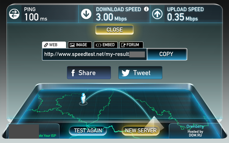
(good speed, bad ping)
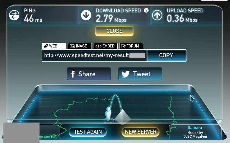
(not very fast, good ping)
Okay, this is a city. You can fish with a nail, as they once said. I pointed this antenna at the floor and even so I caught some echoes of the signal.
But now the time has come to leave the city. I am in a wooden log house with a metal roof. Phone reception is so-so, the Internet is at GPRS speeds. I catch the nearest BS.
It would seem sparse. But there is Internet, and it is UMTS (and it would try to be different with such and such an antenna!) Let’s try Speedtest...
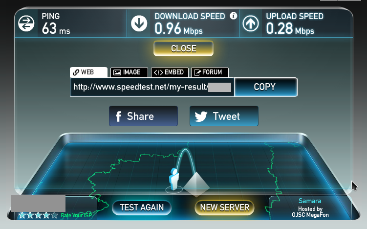
Like this! Almost a megabit!
At this stage I realized: the antenna works in this configuration. You can begin to protect against mechanical influences, dirt and moisture.
Preparing for hiking conditions
At first I wanted to place the antenna in a specialized box for external wiring. However, a friend suggested to me a much simpler, cheaper and more durable solution: a polyethylene container for a microwave oven. Indeed, polyethylene is more durable and certainly transparent for the frequencies of interest to us. In addition, such containers are available in almost any hardware store, and boxes with pressure seals must be looked for in specialized stores.The disadvantage of this solution is that you have to farm collectively. But this, as everyone has already understood, does not scare me.
I didn't even need to return to the city to complete the structure. I found almost everything needed for assembly at a local general store, and I had the rest (including tools) with me:
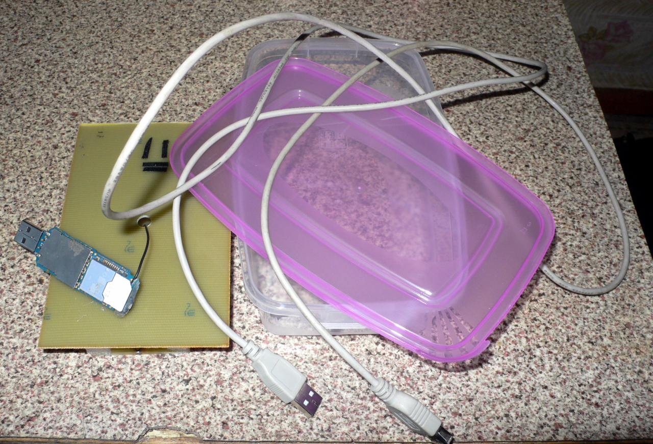
To begin with, I inserted the USB cable inside the container (I had to cut it and solder it again so as not to make a huge hole):
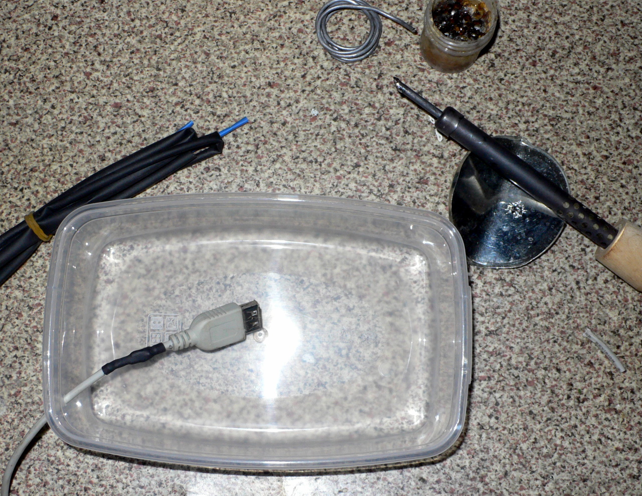
Then I put the soldering iron aside and grabbed one of my favorite tools: a Chinese hot snot glue gun. We seal the cable entry:
![]()
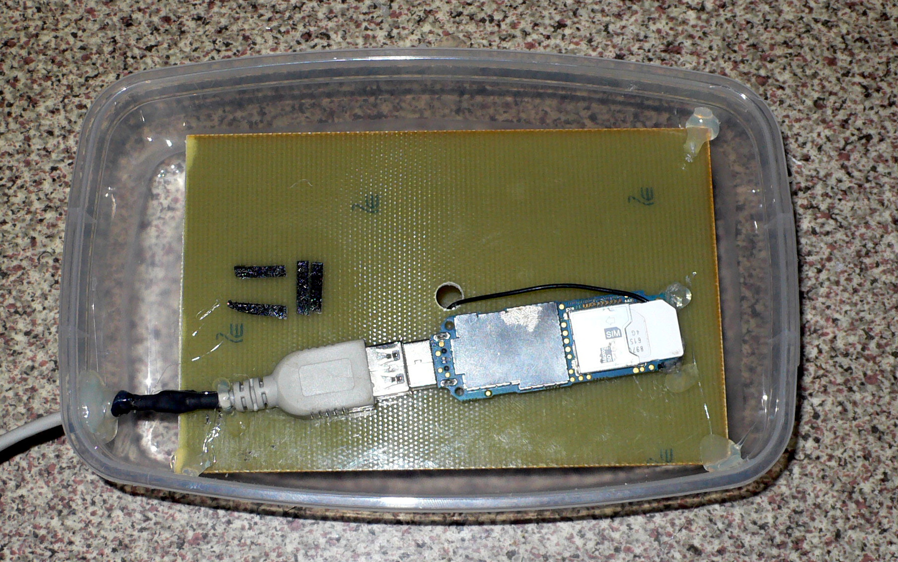
We fix the antenna inside, grab critical places with drops of glue so that nothing dangles when carrying:
We fuse two ugly piles of not very neat legs so that the antenna can be placed on a more or less flat surface:
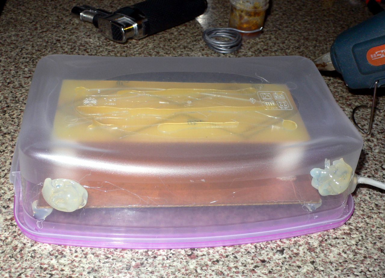
After all these exercises, the antenna, of course, still works as before, because nothing has changed in the radio frequency part, and USB is