Homemade UHF antenna for digital television. UHF antenna with amplifier. Kharchenko zigzag antenna
Modernization of the "Polish" antenna for T2
You can use the “Polish” antenna completely assembled with an amplifier without modification, but as experience shows, some frequency channels have a weak signal level.
We are all surprised by the versatility of the “Polish” antenna, and the Polish antenna is nothing more than the simplest combination of the simplest universal “butterfly” antenna, widely known since the 60s, with a vibrator length of 1150 mm and an opening angle of 38° for reception from 1 to 12 th channel in line of sight conditions
and a primitively designed “wave channel antenna”, and not a single size fits into any calculations or GOSTs. That is, we have a usual, practically, dummy UHF antenna in a “Polish” antenna for UHF reception (I’m talking about directors-passive selectors). It turns out that only a “butterfly” works in this antenna, or rather several “butterfly”-active selectors and I will also note those designed for a certain range (they are all the same length), and an SWA amplifier.
If you remove the SWA amplifier, the antenna will not work. What I am saying is that it is enough to bend such an active vibrator of a certain size (we will talk about this below), connect the SWA amplifier. To balance the RF, you need to run the cable along the arm of the vibrator according to Fig. 2. Effect we'll get a much better "Polish"
ATTENTION: the cable is routed along the arm of the active vibrator that is connected to the “body” of the amplifier circuit! At the midpoint of the vibrator, where the HF potential is zero, we bend the cable smoothly and direct it along the traverse, then downward.
In short, any homemade antenna + SWA amplifier works much better better than any"Poles".
But we already have what we have. Let’s try to bring it a little into a normal UHF form. “Meter” mustaches (long active vibrators, see Fig. 1) are absolutely not needed; if we use an antenna for T2 (UHF wavelength), they can be cut to the same length as decimeter active vibrators. If one of the received channels is weaker than the others, you should try to remove the reflector sheet from the active vibrators. When adjusting the antenna in this way, its output impedance increases and changes frequency response. Changing the antenna impedance does no harm at all, since the input impedance of the amplifier is higher than the antenna impedance. Radio amateurs with experience working with antenna amplifiers, they can remove the matching-balancing elements on the ferrite ring from the amplifier circuit, this will expand the range of operation active antenna. One of the antenna input terminals is connected to the amplifier input, and the second is connected to the “case” of the amplifier circuit.
The antenna resistance at equal received power is related to the output voltage
P=U2/R. U=(P*R)½.
The conclusion that follows is that it is necessary to increase the output impedance of the antenna (the input impedance of the amplifier is greater than the impedance of the antenna). Antennas with a resistance higher than 300 ohms can be successfully used. This connection method is also suitable for a wide-range antenna of the “wave channel” type (more on this later), and in a log-periodic antenna the output cable is balanced, passing through the antenna element (according to the principle of Fig. 2).
Somehow I have a lot of abstruse anecdotes, you’ll think that I’m as smart as.... No, it’s all simple - should you google mine?
I'll try to keep it simpler
I don’t recommend trimming “long mustaches” if you’re doing it for yourself, if you’re lazy, or for your “uncle,” I advise you to shorten it based on L (Length of the vibrator) = 1/2j (half the average length of the weak frequency channel)
And for ourselves, we bend two diamonds and remove the reflector from the back of the diamonds, or insert the sleeve into the mount and bend it 10 cm
Now let’s do some magic with the directors. I have already mentioned the “wave channel” antenna, this miracle is known from the times of black and white TV
So let’s take the dimensions of the directors and the distances between them from the “grandfather’s” antenna that has been tested over the years.
Vibrator no. length in mm distance in mm
7…………………………..107...............0
6…………………………..129..............80
5…………………………..155..............94
4…………………………..186..............77
3…………………………..225..............63
2…………………………..272..............53
1…………………………..330...............43
0....................................... ...........35
High-quality MV-UHF antenna "wave channel" with your own hands
This type of antenna refers to targeted UHF antennas.
Since the gain of the targeted UHF antenna is better than that of the Polish-array, it was decided to make a “hybrid” from the old domestic UHF antenna and the ASP-8 Polish-array with its amplifier. It worked! The image quality of weak images has improved noticeably. The idea of manufacturing was proposed somewhere by someone, all that remained was to implement it.
I will tell you simply, without any abstruse expressions and formulas.
For self-made antennas needed:
Special program for calculating Antwu15;
1 or 2 amplifiers from the grid (with housings);
Aluminum pipe cross section? o 25mm and length? 2m. (traverse);
3 aluminum tubes with a cross-section of up to o10mm, two lengths of 1m each (MV) and another? 2.5-3m. (for cutting UHF elements);
2 sheets of textolite 3-5 mm thick, dimensions: 300mmx150mm (for mounting MV);
You will also need self-tapping screws (20 pcs 15 mm) and bolts with nuts (thread x3 6 pcs 20 mm) (for fastening DMV and MV elements);
Attention What is critical here is the distance from the active vibrator “two diamonds” or “butterfly” (cut off long mustaches) as someone did, also for other “butterflies” to the first director (if of course there is a desire to change the wires (tubes), here segments from long mustache
The last figure shows the dimensions and distances for channel frequencies in the band 21... 41. For other frequency channels, the dimensions can be calculated using the Antwu15 () program
So, first, let's look at the program. With its help, you can calculate various antenna options tuned to different bands. Let's launch. We are only interested in the first point
It's simple. We enter the data to which the antenna will be configured, and the program will do everything itself.
For example:
The center frequency of the antenna implies the broadcast frequency of the last 61-69 channels. The number of elements determines the length of the traverse. We set the diameter of the elements to 1-5 (not so significant).
The method of fastening the elements is through a traverse. We agree, and as a result we get ready-made sizes for our product.
Below is the result obtained, based on which one of the UHF antenna options was made. This option ensures stable signal reception from a tower 80 km away through splitters for two TVs and a PCI-TV tuner in a computer.
All that remains is to assemble. The length of the antenna is determined by the number of elements
I advise you to install directors for one frequency range on each “butterfly” (they will all be the same length) - four “butterflies” correspond to four frequency channels Ukraine
Here is another table of director lengths for a universal log-periodic antenna (counting from the “butterfly”) with 21....64
We discussed how to use the program above.
We get the dimensions calculated by the program. All that remains is to assemble. The length of the antenna is determined by the number of elements, you can calculate 1.4 m, but the gain will be less. IN overall choice behind you.
To obtain better shielding from the reflected signal, the role of a reflector can be performed by a grid-screen from the ASP-8 “Polish” antenna, dimensions: length - as in the calculation of the program, height 300 mm. Curved edges point forward. You can also use other material in the form of sheet iron, aluminum, or use it from old UHF antennas.
Now we prepare the MV antenna from two meter vibrators. It's much easier here. Its role will be played by 2 tubes with a cross-section of 10 mm and a length of 1 m, folded at an unfinished angle of 120 degrees. This part of the antenna can not be assembled if we do not need strictly meter waves for T2. And what kind of antenna do we have?
Here is a sketch of the resulting “monster”:
Well, let's go back to our "rams" - let's finish assembling the antenna.
Next we take the traverse. We make its length 5 cm longer for attaching the MV antenna. The traverse is an aluminum tube with a cross-section. 25mm. and make notches on it in the places where the elements, loop vibrator and reflector are attached. Distance according to the calculated table. We drill 10mm holes through them at right angles and insert the elements into them. You can attach elements in different ways: using self-tapping screws on top, cutting threads in the elements with bolts, or putting rubber tubes on the elements, insert them tightly into the holes of the traverse.
The heart of the antenna is a loop vibrator, which can be made from an aluminum plate 13mm wide, or an aluminum or copper tube with a cross-section of 10mm.
The size of the loop vibrator is selected experimentally, already on the assembled antenna.
A loop is not needed; instead we use an amplifier from a “Polish” antenna. We fasten its body with bolts into the holes of the vibrator.
Attention And now we are setting up the “crow”, we are not putting long mustaches - this is the meter part of the antenna, we are putting a reflector from the “pole” and bending it like this, like a UHF antenna with a complex reflector
We carefully attach the antenna to the mast, install the mast, preferably higher, direct it and the “crow” rests. Good luck
Simple TV antenna Do-it-yourself UHF
1. Ring-coaxial cable RK75, 530 mm long.
2. Loop-coaxial cable RK75, 175 mm long.
3. To the console.
Assembly:
To assemble this antenna, you don’t even have to go shopping.
To do this, you need to take an RK75 antenna cable 530 mm long (for the ring) and 175 mm long. (for loop).
Connect as shown in the figure.
Secure it to a sheet of plywood (plexiglass) using wire clamps.
Direct to telecentre.
Here is a UHF antenna that will work no worse than a purchased one.
And if you also go to the market or store, buy an SWA amplifier (we put an SWA amplifier instead of a loop) and a power supply for it (about 40 UAH), then it’s even better than a store-bought one.
Do-it-yourself UHF television antenna “Narodnaya”
The antenna is an aluminum disk with an outer diameter of 356mm and an inner diameter of 170mm. and 1mm thick, in which a 10mm wide cut was made.
A printed circuit board made of glass lite 1mm thick is installed in place of the cut. This board has two holes for mounting with M3 screws.
TO printed circuit board attached to the antenna, solder the leads of the matching transformer T1.
For a transformer, it is best to use a ring core with an outer diameter of 6...10mm, and an inner diameter of 3...7mm. and thickness 2...3mm.
The transformer windings are covered with a single-layer insulated wire with a diameter of 0.2...0.25 mm. and have the same number of turns, from 2 to 3 turns. The length of the coil bends is 20mm.
With such a transformer, reception in the meter and decimeter range is possible at a distance of 25...30 km. At a distance of up to 50 km. The antenna works satisfactorily only on decimeter channels.
Without a transformer, the distance of reliable reception is halved.
However, there is a circuit that allows you to get similar results without a transformer; for this you need to assemble the following circuit:
Here, too, you can use an SWA amplifier (we put an SWA amplifier instead of a transformer) and a power supply to it. But as experience shows, a transformer to which we supply power from the power supply from a “Polish” is better.
UHF television antenna with a simple do-it-yourself reflector
Taking this antenna as a basis, I bent a big mustache on the “Polish” one.
1. frame made of aluminum strips
2. amplifier
3. mast
4. reflector
A. Braid soldering point
B. soldering point of the central core
Assembly:
1. First, a frame is assembled from aluminum plates, overlapping, as shown in the figure, using bolts (after fastening, the fastening points should be painted with paint to avoid oxidation).
2. Next, a coaxial cable is soldered at points A and B.
3. bolt the frame to the mast
4. make from rods with a diameter of 3...10 mm (or you can simply use a reflector from a collapsed polish or reinforcement for peeling walls), attaching the reflector to the mast with brackets
5. Attach the amplifier to the mast and connect the coaxial cable to it.
Assembly is possible without a reflector, but the gain of such an antenna will be lower.
Do-it-yourself UHF television antenna with a complex reflector
1. frame made of aluminum strips (reflector from a collapsed polish or reinforcement for plaster walls)
2. amplifier
3. mast
4. reflector (reflector from a collapsed polish or reinforcement for tickling walls)
Assembly:
1. first of all, the frame is assembled from aluminum plates, as for a simple reflector
2. Next, a reflector of the “dilapidated box” type is assembled as shown in the figure (the design of such a reflector can be very different, it all depends on your capabilities).
3. The reflector is attached to the mast with metal brackets
3. Next, the amplifier is attached to the mast, and the coaxial cable is soldered, the same as for a simple reflector.
On decimeter waves in the range 470-638 MHz (channels 21-41), directional antennas can be used as indoor antennas, since their sizes at these waves are relatively small. As directional indoor antennas for decimeter waves, the most convenient antennas are the “wave channel” type.
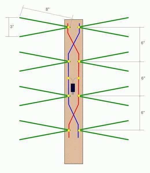
Figure 1 shows appearance indoor UHF antenna ATKD-2 of the “wave channel” type, operating without tuning on channels from 21 to 41 in the range 470-638 MHz. The geometric dimensions of the antenna are shown in Fig. 2a. The antenna consists of a base with a stand and a removable antenna sheet. The antenna sheet contains an active vibrator 1, a reflector 2 and two directors 3 and 4, which are made of brass or steel tape and attached to a plastic boom.
The reduction cable 5 is connected to the antenna through a short-circuited balun bridge (Fig. 2, b), the length of which is equal to a quarter of the wavelength at the middle frequency of the range 470-638 MHz. The bridge is formed by a two-wire line, one conductor of which is the metal screen of the reduction cable, the second is section 6 of the mounting wire MGShV with a cross-section of 0.35 mm2. At a distance of 140 mm from the antenna input terminals, equal to the required bridge length (a quarter wavelength at a frequency of 550 MHz), the mounting wire is soldered to the cable screen. The gain relative to a half-wave vibrator is at least 5.5 dB.
Here is another option for bending the “long mustache” of the Polish antenna and replacing the directors (for the range 42...64 we calculate the length and distance using a program)
Do-it-yourself UHF television log-periodic antenna
To make a web of tubes, two hoops should be unbent, and then bent according to the given template and both halves of the figure should be riveted together.
Notches should first be made on the tubes at bend points (after about 200 mm). The antenna can be attached to the mast with getinax plates or wooden blocks (three are enough). The cable is laid along the canvas in accordance with the upper figure.
To protect against corrosion, the soldering points and connections between the strips and the fabric are coated several times with BF glue (such protection is enough for several years). The braid must be soldered to the strip of the half of the antenna along which the cable is laid. To obtain the maximum signal, you need to add a reflector made of metal strips (screw it directly to the mast with screws). The distance between the antenna sheet and the reflector is selected according to best picture(110... 160 mm). Dimensions are given in accordance with the setting for channel 30 in Fig.
Well, if you don’t want to sweat it, we make a transformer like in the “folk” one or install an SWA amplifier.
However, due to its wide-bandwidth, the antenna receives signals well in the range from the 21st to the 40th channel. Such an antenna even without a reflector gave best results than a 16-element wave channel, all other things being equal. As we see, this antenna is more powerful for the “butterfly” and “wave channel”, and as I already said in the “Polish” director’s antenna, this is a dummy, so we throw out all the “butterflies” from the aluminum wire with a diameter of 6 mm, we bend two halves of semi-diamonds according to the template, inserting them into the fastenings instead of butterflies. Well, we move the reflector to the required distance (here is another option for upgrading the “poles”)
Added after 53 minutes 13 seconds:
Do-it-yourself universal car television antenna
All-wave car TV antenna with pie chart directivity in the horizontal plane. This antenna can also be used in stationary conditions, i.e. not only in a car, but also for home TV. You can also take the modernization of the “Polish” antenna as a basis - bend the “long mustache” with a ring of a certain diameter, or rather bend it like this, connecting with the neighbor’s butterfly - this is one mustache, and the second bend as in Indoor antenna decimeter waves "wave channel" active loop vibrator for example (remember, the size is taken to be 1/2 the wavelength of the poorly indicating range)
car television antenna consists of
1. 2 aluminum rings (d=270mm and d=130mm)
2. wooden slats (3x3cm)
3. TV cable
Assembling a car television antenna
Such an antenna can be built using a commercially available 300/75 Ohm plug (see figure) with a matching transformer inside it for imported TVs.
Two aluminum rings are attached to the plug using the screws on it: one with a diameter of 270 mm for the UHF range (channels 6-12), the other with a diameter of 130 mm for the UHF range (channels 23-51). Since the MV ring is not suitable for us (we need a channel range of another 51...64), we change it to a calculated one with a diameter of 90 mm. The antenna made in this way is attached to a wooden rail with a cross-section of 3x3 cm with a hole for a plug plug. The plug is attached to the rail with electrical tape, and the rings are secured with two insulators to give rigidity to the system. The rail is bolted to the trunk frame located on the roof of the car. Using a standard industrial cable (plug-socket) RK-75-4-11, the antenna is connected in the rear compartment of the car to the car TV.
To increase efficiency, the antenna can be equipped with an amplifier (SWA-7 or SWA-9) powered by a car battery.
Do-it-yourself universal “can” UHF television antenna
The proposed antenna uses available materials. But, nevertheless, it operates in the entire UHF TV range, and is not inferior in parameters to a standard six-element log-periodic antenna produced in series.
To make this antenna you will need two empty tin cans with a diameter of 7.5 cm, a length of 9.5 cm and two small strips of filtered fiberglass.
The cans are connected by strips of fiberglass by soldering. The top strip is solid, and the foil on the bottom is cut (as shown in the figure)
for connecting a 75-ohm power cable.
Total antenna length to work in all UHF channels must be at least 25 cm.
This antenna is something like a symmetrical broadband vibrator. Due to the large surface area, it has a high gain. When using small-diameter cans, it is necessary to make a cut in the foil in the top strip.
Added after 16 minutes 44 seconds:
Do-it-yourself UHF frame television antenna
This antenna has a high gain and can be used both indoors and outdoors. It is characterized by ease of manufacture, availability of materials, small size, and aesthetic appearance.
The antenna design is shown in the figure, dimensions are in the table:
The basis is a three-frame antenna. To make an antenna, any wire made of copper, brass, steel, aluminum, etc. with a diameter of 3...8 mm is taken and bent according to the pattern. The wires are soldered at the joints. The antenna cable is soldered to points A and B. At point C, the cable braid is connected to the antenna material.
You can take this antenna as the basis for modernizing the “Polish” antenna - bending the long mustache in the form of an average square, taking into account that B (Polish) = 1/2 B (frame)
Digital television T2 is gaining momentum in popularity. And this is natural, analogue television is being replaced by digital television and this is an irreversible process. Moreover, in the near future, analogue broadcasting will be stopped altogether. What should users who have TVs without a T2 receiver do? cable television? The answer is simple - buy a T2 set-top box. Today, the price of T2 consoles has dropped greatly and does not look exorbitant. The advantages are quite big: you have many channels in digital quality, no monthly fee, with minimum costs and without buying a new TV. Only by comparing the quality of digital and analog TV will you never regret your choice.
Quite a lot has been written on the choice of T2 receivers. Moreover, new models are constantly being released. I would advise taking an inexpensive one, but new model, after reading reviews on online store websites. As a rule, any receiver works, but the antenna has great value. Even if you are close to a TV tower, but are blocked by high-rise buildings, etc. - and this is almost always, then good antenna- a guarantee of problem-free (and most importantly, nerve-free) quality reception maximum number of digital TV channels.
But an expensive antenna is not always a good antenna. Especially if you are 50 km or more away from the TV tower. Stores offer “special” antennas for T2. In fact, there is nothing “special”; you need a good antenna for the DCM range. If you still have an old DCM antenna, try connecting it first. Widespread "Polish" antennas are not suitable for receiving T2 digital channels.
I offer a proven option that is simple, but at the same time has proven itself, homemade antenna for T2. The shape of the antenna is not new; it has been used for a long time and when receiving DCM analog television, but the dimensions are optimized for receiving T2 digital channels.
It is worth noting that the Internet offers large number options homemade antennas for T2: from beer cans, from the antenna cable, converted Polish, etc. This is for the completely lazy, and you shouldn’t expect quality from such antennas.
So. The long-known “figure eight” was taken as the shape of the antenna. The antenna body is made of any conductive material of suitable cross-section. This can be copper or aluminum wire with a thickness of 1 to 5 mm, a tube, strip, busbar, corner, profile. Copper is, of course, preferable. I used 6mm diameter copper tube. Good option and copper wire. I just had such a pipe.
Dimensions
The outer side of the square is 14 cm, the inner side is slightly smaller - 13 cm. Due to this, the middle of the two squares does not converge, leaving a gap of about 2 cm.
In total, you will need a tube, wire or other material 115 cm long (with a small margin).
The first section is 13 cm + 1 cm for a loop (for strength), if made of wire, or riveted for overlapping soldering for a tube. The second and third - 14 cm each, the fourth and fifth - 13 cm each, the sixth and seventh - 14 cm each, and the last eighth - 13 cm + 1 cm, again for connection.
We strip the ends by 1.5 - 2 cm, twist the two loops behind each other, and then solder the joint. This will be one cable connection pin. After 2 cm another.
From a copper tube it looks like this

It’s a little more difficult to bend the tube, but we don’t need much precision. Minor flaws in the shape do not affect the performance of the antenna. But the fact that the conductor area increases is a plus. Well, the conductivity of copper is higher than that of aluminum and, especially, steel. The higher the conductivity, the better reception antennas.

The connection prepared for soldering is first riveted and cleaned. For soldering you need to use a powerful soldering iron (from 150 W). Simple amateur radio at 30 watts. don't solder. You can use acid for soldering.

Check the geometry again and solder the connection


If you are not particularly bothered by the aesthetic appearance, you can simply attach the antenna to a glazing bead or any other available holder. This antenna was located in the attic, so the simplest mounting method was used - electrical tape. If the antenna will be placed outdoors, take care of more aesthetic and reliable mounting.

This is a version of the T2 antenna made of aluminum wire with a diameter of 3 mm. Secure with one screw to the window. The distance to the TV tower is about 25 km. True, it’s the 6th floor, I didn’t check it below, but under these conditions the signal level is 100% and the quality is 100%. The cable is old, 12 meters to the TV. Receives all 32 channels. At first I was worried that it wasn’t copper, but as it turned out, it was in vain. Everything worked out perfectly on ordinary aluminum wire (which happened to be available). That is, if you have a zone confident reception, then you don’t have to bother and feel free to use aluminum (I don’t know, maybe steel will do).

This antenna does not use any amplifiers. It is very easy to set up - just turn maximum level signal and quality on your tuner channels. Check other channels and fix the antenna. If reception is poor, you can experiment with not only rotating, but also changing location and height. Very often, the signal can be many times stronger if the antenna is shifted only 0.5-1 m to the side or in height. Good luck - the antenna has been tested - 100% operational and better than at least half, or even more, of purchased antennas, where they save on everything and sell garbage for good money.
Digital terrestrial television(DVB-Digital Video Broadcasting) is a technology for transmitting television images and sound using digital encoding of video and sound. Digital coding, unlike analogue, ensures signal delivery with minimal losses, since the signal is not affected by external interference. At the time of writing, 20 digital channels are available, and this number should increase in the future. This number of digital channels is not available in all regions; you can find out more precisely about the possibility of receiving digital channels on the website www.rtrs.rf. If your region has digital channels, then you just need to make sure that your TV supports DVB-T2 technology (this can be found in the documentation for the TV) or purchase a DVB-T2 set-top box and connect the antenna. The question arises - Which antenna to use for digital television? or How to make an antenna for digital television? In this article I would like to dwell in more detail on antennas for watching digital television, and in particular I will show how to make your own antenna for digital television.
The first thing I would like to emphasize is that digital television does not require a specialized antenna; analog antenna(the one you used previously to watch analogue channels). Moreover, only a television cable can be used as an antenna...
In my opinion, the simplest antenna for digital television is a television cable. Everything is extremely simple, take it coaxial cable, an F connector and an adapter for connecting to a TV are put on one end, and the central core of the cable is exposed at the other end (a kind of whip antenna). All that remains is to decide how many centimeters to expose the central core, since the quality of reception of digital channels depends on this. To do this, you need to understand at what frequency digital channels broadcast in your region, to do this, go to the website www.rtrs.rf/when/ here on the map, find the tower closest to you and see at what frequency digital channels broadcast.
More detailed information you will get if you click the "More details" button.

Now we need to calculate the wavelength. The formula is very simple:
where, λ (lamda) is the wavelength,
c - speed of light (3-10 8 m/s)
F - frequency in hertz
or simpler λ=300/F (MHz)
In my case, the frequency is 602 MHz and 610 MHz, for the calculation I will use the frequency of 602 MHz
Total: 300/ 602 ≈ 0.5 m = 50 cm.
Leaving half a meter of the central core of a coaxial cable is not beautiful and inconvenient, so I will leave half, or maybe a quarter, of the wavelength.
l=λ*k/2
where l is the length of the antenna (central core)
λ - wavelength (calculated earlier)
k - shortening factor, since the length of the entire cable will not be large, this value can be considered equal to 1.
As a result, l=50/2=25 cm.
From these calculations it turned out that for a frequency of 602 MHz I need to expose 25 cm of coaxial cable.
Here is the result of the work done

This is what the antenna looks like when installed.

View of the antenna while watching TV.

For those who want to set up an antenna for television, understand this: digital gizmos were not created by nature. There are analog signals in the Universe, the power varies according to the quantum states of electrons. The transitions are so small that to a person they seem continuous. The signal can be represented by a certain number multiplied by elementary energy. We would like to make it clear: the nature of a digital signal is not understood by mankind; a digital antenna cannot be constructed independently. It is possible to make an antenna for reception analog signal, carrying digital information.
Digital signal reception antennas
Today it is exclusively digital television. However! Multiplexes, where programs are stamped into frames, contain radio broadcasts. We would like to clarify: in the current state of affairs, radio broadcasting has shifted upward, capturing the frequencies of the FM range, television has been completely pushed out to the UHF. Explained by features modern life. The driver wants to listen to the radio and watch TV on the way. Have you seen the long antennas of walkie-talkies? 34 MHz. Compare: Channel I of the USSR broadcast at 50 MHz. Should everyone on the roof have a two-meter long antenna to watch the central channel?
Just ridiculous. In contrast to sticks, FM-UHF antennas are relatively small. Easily fits on the roof. Easing the suffering of moviegoers, the channels are carried by one frequency. The picture is divided into frames, it turns out that many programs are available with a single antenna setting. Comfortable. Lots of benefits technical solution we will see from the phenomenon called today digital multiplex. It becomes possible to accurately target the antenna at the receiving frequency (which is a trivial UHF channel) in order to watch programs or listen to the radio.
To solve the problem, a device that some consider to be a “homemade digital antenna” is being constructed. The antenna is ordinary, and if you are interested in the type, let’s add – linear. The design was chosen due to its small dimensions. Highlighted in digital transmission one problem...
Television is accustomed to using horizontal polarization. Suffered a fate digital multiplex. It turns out that the signal is caught amazingly when the antenna line is perpendicular to the beam of the incoming signal. If we break the rule, power begins to be lost and reception deteriorates.
Receiving a digital signal with an antenna
Those wishing to receive a digital signal must understand the type of polarization electromagnetic radiation. Discard satellite television, broadcasting in frames, the polarization, as Vladimir Volfovich says, is definitely horizontal. The type of signal is usually caught on television using a half-wave vibrator; there are two types of signal:
- Symmetric.
- Asymmetrical.
Let me explain. The first is formed by identical shoulders equal to a quarter of the wavelength. The total is half the wavelength. The signal core of the cable is connected to one arm, the screen to the opposite. The shoulders form a line in a row, separated by a gap of 20 mm. To match, equalize the resistances of the antenna and cable, take the trouble to balance them. The first condition is ideally satisfied, the second at UHF frequencies plays a lesser role as the wavelength decreases.
To make a digital antenna yourself, it is enough to equip the mast with a supporting plate, attach horizontally and symmetrically two wire arms 3 mm thick, each a quarter of a wavelength.
The resulting device is soldered onto coaxial wave impedance 75 Ohm, as stated above, the length of the reduction cable is taken as low as possible, each meter eats up part useful power losses. Only the length to the first amplifier stage matters. Supplying the roof with power by installing a purchased unit desired frequency, a bay in the corner, rolled up behind the TV, deprives us of the opportunity to spoil the reception. The over-amplification effect sometimes introduces unpleasant visual effects, the most famous is considered ghosting.
Another negative is possible. First you should try an antenna without an amplifier. Reception will not be distorted in any way by excess power. If unpleasant side effects are observed, it is worth trying to improve the quality. It is important to point the antenna more accurately. In the city, due to the multi-beam effect, in the village, due to the deviation of the direction of wave movement from a straight line, the exit point of the beam is not where the compass points (according to the map). You should move the antenna slightly, setting the right direction, finding the best position.
Antenna signal reception
The half-wave vibrator of the design described above forms two main lobes in the radiation pattern. Spaced 180 degrees. The radiation pattern is symmetrical in the horizontal plane. Therefore, we will improve the characteristics by installing a screen. An obvious solution, we rarely see it for a simple reason: the antenna must catch a wide range, it is difficult to choose the correct distance. For a half-wave vibrator, the screen will not be a piece of conductive material - a couple of pieces of wire from which the arms are made. The distance between them is not so important and should not be large. 5 centimeters up and down from the plane of the shoulders is quite enough. The screen length exceeds the span of both and is electrically located on the cable braid.
The distance between the screen and the half-wave vibrator becomes important. We find it difficult to answer correctly what gap separates the parts; for zigzag loop antennas the value is 0.175 of the signal wavelength. We believe that amateurs have the right to try to experimentally select the desired distance; professionals have a chance to simulate the MMANA system. The former will get an acceptable result faster, the latter will be able to predict the final layout of an arbitrary wavelength, which is preferable. Modeling antennas is not among the interests of the authors; enthusiastic people are able to post a finished file, flavoring the comments with the fruit of technical thought. We believe that the alignment will reduce the amount of interference.
Single-ended digital antenna
As for the asymmetrical half-wave vibrator, it represents one shoulder. The second is replaced by “earth” (an infinite plane of zero potential); in practice, there is simply nothing in this place. The manufacture of a half-wave asymmetrical vibrator has been repeatedly shown on forums, the VashTekhnik portal, and the network. Typically, the antenna serves as an indoor addition to a digital receiver that is afraid to catch on its own. To make the fixture, the channel wavelength is calculated and divided by four. The cable screen is stripped along the segment, the internal insulation is preserved - it will not interfere with reception.
An F-connector is screwed onto the end bent 90 degrees, which is inserted into the receiver, TV socket (contain the receiving part of terrestrial digital television with the required generation of microcircuit). Almost all modern plasma panels what you need inside. Setting up will take time, the channel frequency is known. You need to find out the number - visit the website http://rtrs.rf, look at the region, call the required phone number. Requests by e-mail are accepted. Of course, if the region is deprived of digital television, no information will be found.
The given site is official resource a state unitary enterprise entrusted with the task of digitizing the space of the Russian Federation. Ask if you can make a log-periodic digital antenna yourself? The answer is no need. The log-periodic antenna covers a wide range, if you want to watch three Moscow multiplexes, take it. Discarding caution, use a wave channel type antenna, which differs from the log-periodic one in slightly worse range characteristics and is simpler in design. The manufacturing method was discussed; the province has little point in wasting time.
Readers understand: the design of a digital antenna is identical to the usual one. Polarization is linear horizontal, frequency is determined by the channel. The operating principle of a digital antenna is similar. Conversion of an electromagnetic wave into current inside a conductor. Peculiarity digital antennas- precisely tuned to one frequency. The design is simple and effective. Promising high-quality viewing (without visual, audio interference). Naturally, the TV and set-top box must decode the signal.
All that remains is to say goodbye to the readers. Today the amateur radio industry is becoming a thing of the past, who will predict the awaiting humanity of tomorrow...
Decimeter waves with a length fall within the range of 10 cm - 1 m. This feature serves as the basis for naming devices. At frequency electromagnetic vibrations They propagate predominantly in a straight line, avoiding going around the earth's surface, and are partially reflected by the troposphere. Therefore, long-distance UHF communication is difficult; the range does not exceed 100 km. Can a decimeter antenna be assembled with your own hands? Maybe it is being actively collected by amateur engineers.
Beer cans will receive television broadcast
UHF frequencies are located in the range 300 MHz - 3 GHz. This includes many commercial, public channels.
The program “Cheap and Cheap” taught Muscovites how to catch Channel One. According to available data, it is transmitted by the HF band, the sound is adjacent to FM radio stations, the homemade design demonstrated by the presenter is used by the UHF.
You will need two beer cans with a capacity of 0.5 liters (larger volume, lower received frequencies). You can save money by buying mineral water and juice in cans. To attach the mentioned containers you will need a frame.
Channel One recommends using a wooden board 10 cm in diameter; enthusiasts have come up with a constructive solution. It is proposed to hang the jars on an ordinary wooden hanger. An indoor decimeter antenna made in a similar way can easily be placed on a window handle or a wall nail.
In addition to two beer cans you will need:
- A pair of sharp screws (screws) with a diameter of 2-3 mm, a screwdriver.
- A piece of coaxial cable from the antenna location to the TV.
- One standard jack connector.
- A roll of adhesive tape, insulating tape.
- A soldering iron, rosin, solder, and a pair of terminals for the screws indicated in step 1 will come in handy.
You should start by sealing the connector and terminals into the wire. The first will be located on the TV side, the second - on the opposite end (core, screen). Both terminals must be separated by 12 cm.
The design of the antenna avoids complications: the cans are secured with a horizontal crossbar with their necks facing each other at a distance of 75 mm from each other. Assembly begins by attaching the terminals to the necks with screws. There is no need to tighten it all the way, the wires should be pressed tightly against the cans.
The containers are secured parallel to each other with tape on a hanger. The homemade decimeter antenna is ready. Hanging the hanger in place best regards- first you need to find one - cover it with a curtain, clothes. According to eyewitnesses, the design works, equipped with cans of a more modest displacement. You can actively experiment by changing the distance between the containers and visually assessing the image quality.
Standard TV wire ring
The design will not require anything other than a coaxial cable with a resistance of 75 Ohms (RK 75). An even ring is bent from a piece 530 mm long and reinforced with plywood and plexiglass. High input impedance will not allow you to create a direct connection to the TV; a special matching device is used - a U-elbow.

A piece of cable 175 mm long is bent into a U shape. The ends are aligned with the edge of the wire going to the TV on both sides. The structure is fastened with tape or any other suitable material. Three screens are soldered to each other. The conductors of the U-elbow are connected to the shield of the curved ring on both sides, the central wire TV cable- with one.
It turns out passive antenna decimeter range. For outdoor use, coat the cable with a compound, resin, and enclose the product in a durable, impermeable plastic casing.
Wi-Fi, TV rings
Two aluminum circuits
“Cheburashki” firmly captured oblivion, but it turned out not completely. Many people have seen a flat aluminum plate equipped with huge rings on the sides. How to make a decimeter antenna with your own hands? You will need two flat aluminum rings with an outer diameter of 100 mm and an inner diameter of 38 mm. Each is cut through with a 5 mm wide slot.
It turns out that two circuits will avoid the use of a transformer. The frame will be a fiberglass lath, a piece of durable board. Both rings are attached with a distance between centers of 103 mm towards the slots. The upper and lower edges of the slits are connected in pairs. The screen and the core of the coaxial cable going to the TV are connected to the resulting pairs.
The antenna decorates the balcony, room, roof. The length of the coaxial cable to the TV is shorter, the reception is more reliable.
The circuit is formed by circular vibrators. With horizontal polarization of the wave, there is no phase difference between the symmetrical rings located one above the other, the cable removes the received radiation from the isthmus.
The resonant frequency of the product is 802 MHz, allowing the use Wi-Fi networks 900 MHz, viewing television channels 38 - 64. The UHF antenna fits perfectly with the RK-75 coaxial cable, demonstrating a gain of 15 dB.
The structure is positioned vertically, the slots should be one above the other, respectively, the polarization of the received signal is horizontal.
Two getinax circuits
Radio amateurs may find another method of manufacturing the described design attractive: the required shapes are cut out on the getinax board, textolite with one-sided foil. Between the rings, according to the described scheme, it is necessary to leave a contact bridge with an external width of 20 mm and a 5 mm slot inside. Two mirrored holes are drilled for the coaxial cable.

The method is convenient: four fastening grooves cut into the getinax by the edge of the sheet will allow you to firmly secure the product. Use:
- wall;
- frame;
- roof.
The design can be easily transposed to high, low frequencies by changing the geometric dimensions of the circles. It is easier to select the optimal input impedance empirically (by trying practical dimensions).
Sealing is carried out with plexiglass plates equal in size to getinaks. The perimeter of the gap is sealed with liquid nails.
An interesting feature of the antenna type is the possibility of creating a phased array. Two identical structures are mounted vertically above each other, separated by a verified distance (the described example is 406 mm between the centers of the eights). To create a single grid, a summing device is used, formed by two branches 325 mm long, fastened in the middle. The coaxial cable is soldered to the connection point.
One circuit with transformer
Now that it is clear how to make a decimeter antenna, let’s consider the transformer mentioned above, which provides galvanic isolation of the antenna and TV circuits. The basis is the design described above. There is only one circuit, both ends are closed to the primary winding of a miniature transformer, and the coaxial cable of the TV is soldered to the secondary winding.
The core, formed by several turns of wire, plays the role of a matching device. To manufacture a hinged element, it is necessary to take a ring core with an outer diameter of less than 10 mm and a thickness of 2-3 mm. With a wire with a diameter of 0.2 - 0.25 mm, two windings are wound side by side, each with several turns.
The design is not inferior in efficiency to the dual-circuit models described above. Polarization - horizontal (the slot should be positioned vertically).

Digital television
UHF antennas for digital television are relatively simple to manufacture. You will need a wooden square with a diagonal of 200 mm, or a similar object made of plexiglass, a large piece regular cable RK-75.
The option under consideration is part of a zigzag antenna; it perfectly serves the reception range of digital channels, regardless of the presence of direct visibility to the tower. To improve performance, you should purchase an amplifier.
The tip of the wire is stripped to 20 mm. Then a square with a diagonal of 175 mm is bent from the cable. The end is bent outward by 45 degrees, the beginning is bent, stripping an area of 20 mm, and tightly wound to the end. Provided reliable contact screens. The end of the vein hangs in the air.
At the corner opposite to the beginning, the protective layer is cut off, the screen in an area of 20 mm will be the top of the antenna. The cable square is symmetrically fixed around the perimeter of the wooden sheet. In the area where the screens meet - where the beginning and end are wound to each other - thick copper wire staples are used for fastening to improve electrical contact.
This is how you make a UHF antenna with your own hands. For outdoor use, it must be protected by a plastic case against the influence of the external environment, or securely hidden by the opening of the attic window. The signal rarely passes through metal, tiles, slate. If the roof is made of PVC, plastic, fabric, or similar materials, it is permissible to place the product in the attic.
To block the multipath effect, a reflector shaped like a piece of wood is used. It is secured with ebonite struts coaxially with the antenna.
The designs considered are designed to receive waves with linear polarization. The use of helical antennas may be necessary.