Simple Arduino circuits for beginners. Arduino PRO. Where is the best place for a beginner to start?
This simulator works best on the Chrome browser
Let's take a closer look at Arduino.
Arduino is not a large computer that can be connected to external circuits. Arduino Uno uses Atmega 328P
This is the largest chip on the board. This chip executes programs that are stored in its memory. You can download the program via usb using Arduino IDE. USB port also provides power to the arduino.
There is a separate power connector. The board has two pins labeled 5v and 3.3v, which are needed to power various devices. You will also find pins marked GND, these are the ground pins (ground is 0V). The Arduino platform also has 14 digital pins, labeled 0 to 13, which connect to external nodes and have two states, high or low (on or off). These contacts can work as outputs or as inputs, i.e. they can either transmit some data and control external devices, or receive data from devices. The next pins on the board are labeled A0-A5. These are analog inputs that can accept data from various sensors. This is especially convenient when you need to measure a certain range, such as temperature. The analog inputs have additional features, which can be used separately.

How to use breadboard.
The breadboard is needed to temporarily connect the parts, check how the device works, before you solder everything together.
All of the following examples are assembled on a breadboard so that you can quickly make changes to the circuit and reuse parts without bothering with soldering.
The breadboard has rows of holes into which you can insert parts and wires. Some of these holes are electrically connected to each other.
The two top and bottom rows are connected in rows along the entire board. These rows are used to supply power to the circuit. It could be 5V or 3.3V, but either way, the first thing you need to do is connect 5V and GND to the breadboard as shown in the picture. Sometimes these row connections may be broken in the middle of the board, then if you need to, you can connect them as shown in the picture.


The remaining holes, located in the middle of the board, are grouped into groups of five holes. They are used to connect circuit parts.

The first thing we will connect to our microcontroller is an LED. The electrical connection diagram is shown in the picture.

Why is a resistor needed in a circuit? IN in this case it limits the current that passes through the LED. Each LED is designed for a certain current, and if this current is higher, the LED will fail. You can find out what value the resistor should be using Ohm's law. For those who don’t know or have forgotten, Ohm’s law says that there is a linear relationship between current and voltage. That is, the more voltage we apply to the resistor, the more current will flow through it.
V=I*R
Where V- voltage across the resistor
I- current through the resistor
R- resistance that needs to be found.
First, we must find out the voltage across the resistor. Most 3mm or 5mm LEDs you will use have an operating voltage of 3V. This means that we need to extinguish 5-3 = 2V at the resistor.
We will then calculate the current passing through the resistor.
Most 3mm and 5mm LEDs glow at full brightness at 20mA. A current greater than this can disable them, while a current of lesser intensity will reduce their brightness without causing any harm.
So, we want to connect the LED to the 5V circuit so that it carries a current of 20mA. Since all the parts are included in one circuit, the resistor will also have a current of 20mA.
We get
2V = 20 mA * R
2V = 0.02A * R
R = 100 Ohm
100 Ohms is the minimum resistance, it is better to use a little more, because LEDs have some variation in characteristics.
IN in this example a 220 ohm resistor is used. Only because the author has a lot of them: wink: .
Insert the LED into the holes in the middle of the board so that its long lead is connected to one of the resistor leads. Connect the second end of the resistor to 5V, and connect the second lead of the LED to GND. The LED should light up.
Please note that there is a difference in how you connect the LED. Current flows from the longer terminal to the shorter one. In the diagram you can imagine that the current flows in the direction where the triangle is directed. Try turning the LED upside down and you will see that it will not light up.
But how you connect the resistor makes no difference at all. You can turn it over or try connecting it to a different pin of the LED, this will not affect the operation of the circuit. It will still limit the current through the LED.
Anatomy of Arduino Sketch.
Programs for Arduino are called sketch. They consist of two main functions. Function setup and function loop
Inside this function you will set all the basic settings. Which pins will work as input or output, which libraries to connect, initialize variables. Function Setup() runs only once during the sketch, when program execution starts.
this is the main function that is executed after setup(). In fact, it is the program itself. This function will run indefinitely until you turn off the power.
Arduino flashing LED

In this example, we will connect an LED circuit to one of the Arduino's digital pins and turn it on and off using a program, and you will also learn several useful functions.


This function is used in setup() part of the program and serves to initialize the pins that you will use as input (INPUT) or exit (OUTPUT). You will not be able to read or write data from the pin until you set it to respectively pinMode. This function has two arguments: pinNumber is the pin number you will use.
Mode-sets how the pin will work. At the entrance (INPUT) or exit (OUTPUT). To light the LED we must give a signal FROM Arduino. To do this, we configure the output pin.
- this function is used to set the state (state) pina (pinNumber). There are two main states (actually 3 of them), one is HIGH, there will be 5V on the pin, that’s something else Low and the pin will be 0v. This means that in order to light the LED we need to set the pin connected to the LED to high level HIGH.
Delay. Serves to delay the operation of the program for a period specified in msec.
Below is the code that makes the LED blink.
//LED Blink int ledPin = 7;//Arduino pin to which the LED is connected void setup() ( pinMode(ledPin, OUTPUT);// setting the pin as OUTPUT) void loop() ( digitalWrite(ledPin, HIGH);// turn on the LED delay(1000);// delay 1000 ms (1 sec) digitalWrite(ledPin, LOW);//Turn off the LED delay(1000);//wait 1 sec)
Small explanations on the code.
Lines that start with "//" are comments and are ignored by Arduino.
All commands end with a semicolon; if you forget them, you will receive an error message.
ledPin is a variable. Variables are used in programs to store values. In this example, the variable ledPin the value is assigned to 7, this is the Arduino pin number. When the Arduino program encounters a line with a variable ledPin, it will use the value we specified earlier.
So record pinMode(ledPin, OUTPUT) similar to recording pinMode(7, OUTPUT).
But in the first case, you just need to change the variable and it will change in each line where it is used, and in the second case, in order to change the variable, you will have to make changes manually in each command.
The first line indicates the type of the variable. At Arduino programming It is important to always declare the type of variables. For now it is enough for you to know that INT announces negative and positive numbers.
Below is a simulation of the sketch. Click start to see the circuit in action.
As expected, the LED goes out and comes back on after one second. Try changing the delay to see how it works.
Control of multiple LEDs.
In this example, you will learn how to control multiple LEDs. To do this, install 3 more LEDs on the board and connect them to resistors and Arduino pins as shown below.
In order to turn the LEDs on and off one by one, you need to write a program similar to this:
//Multi LED Blink int led1Pin = 4; int led2Pin = 5; int led3Pin = 6; int led4Pin = 7; void setup() ( //set pins as OUTPUT pinMode(led1Pin, OUTPUT); pinMode(led2Pin, OUTPUT); pinMode(led3Pin, OUTPUT); pinMode(led4Pin, OUTPUT); ) void loop() ( digitalWrite(led1Pin, HIGH );//turn on the LED delay(1000);//delay 1 sec digitalWrite(led1Pin, LOW);//turn off the LED delay(1000);//delay 1 sec //do the same for the other 3 LEDs digitalWrite(led2Pin , HIGH);//light the LED delay(1000);//delay 1 sec digitalWrite(led2Pin, LOW);//extinguish the LED delay(1000);//delay 1 sec digitalWrite(led3Pin, HIGH);//light the LED delay(1000);// delay 1 sec digitalWrite(led3Pin, LOW);//extinguish the LED delay(1000);//delay 1 sec digitalWrite(led4Pin, HIGH);//turn on the LED delay(1000);// delay 1 sec digitalWrite(led4Pin, LOW);//extinguish the LED delay(1000);//delay 1 sec)
This program will work great, but it is not the most rational solution. The code needs to be changed. In order for the program to work over and over again, we will use a construction called .
Loops are useful when you need to repeat the same action several times. In the code above we repeat the lines
DigitalWrite(led4Pin, HIGH); delay(1000); digitalWrite(led4Pin, LOW); delay(1000);
full sketch code in attachment (downloads: 1187)
LED brightness adjustment
Sometimes you will need to change the brightness of the LEDs in the program. This can be done using the command analogWrite()
. This command turns the LED on and off so quickly that the eye cannot see the flickering. If the LED is turned on half the time and off half the time, it will visually appear that it is glowing at half its brightness. This is called pulse width modulation (PWM or PWM in English). The shim is used quite often, since it can be used to control an “analog” component using digital code. Not all Arduino pins are suitable for these purposes. Only those conclusions near which such a designation is drawn " ~
". You will see it next to pins 3,5,6,9,10,11.
Connect one of your LEDs to one of the PWM pins (for the author this is pin 9). Now run the LED flashing sketch, but first change the command digitalWrite() on analogWrite(). analogWrite() has two arguments: the first is the pin number, and the second is the PWM value (0-255), in relation to LEDs this will be their brightness, and for electric motors the rotation speed. Below is an example code for different LED brightnesses.
//Change the brightness of the LED int ledPin = 9;//an LED is connected to this pin void setup() ( pinMode(ledPin, OUTPUT);// initializing the pin to the output ) void loop() ( analogWrite(ledPin, 255);// full brightness (255/255 = 1) delay(1000);//pause 1 sec digitalWrite(ledPin, LOW);//turn off LED delay(1000);//pause 1 sec analogWrite(ledPin, 191);//brightness by 3/4 (191/255 ~= 0.75) delay(1000);//pause 1 sec digitalWrite(ledPin, LOW);//turn off the LED delay(1000);//pause 1 sec analogWrite(ledPin, 127); //half brightness (127/255 ~= 0.5) delay(1000);//pause 1 sec digitalWrite(ledPin, LOW);//turn off LED delay(1000);//pause 1 sec analogWrite(ledPin, 63); //quarter brightness (63/255 ~= 0.25) delay(1000);//pause 1 sec digitalWrite(ledPin, LOW);//turn off the LED delay(1000);//pause 1 sec)
Try changing the PWM value in the command analogWrite() to see how this affects brightness.
Next, you will learn how to adjust the brightness smoothly from full to zero. You can, of course, copy a piece of code 255 times
analogWrite(ledPin, brightness); delay(5);//short delay brightness = brightness + 1;
But, you understand, this will not be practical. The best way to do this is to use FOR loop which was used previously.
The following example uses two loops, one to decrease the brightness from 255 to 0
for (int brightness=0;brightness=0;brightness--)( analogWrite(ledPin,brightness); delay(5); )
delay(5) used to slow down the fade-in and fade-out speed 5*256=1280ms=1.28sec)
The first line uses " brightness-" to make the brightness value decrease by 1 each time the loop is repeated. Note that the loop will run until brightness >=0.Replacing the sign >
on the sign >=
we included 0 in the brightness range. This sketch is modeled below. //smoothly change the brightness int ledPin = 9;//an LED is connected to this pin void setup() ( pinMode(ledPin, OUTPUT);// initialization of the output pin) void loop() ( //smoothly increase the brightness (0 to 255 ) for (int brightness=0;brightness=0;brightness--)( analogWrite(ledPin,brightness); delay(5); ) delay(1000);//wait 1 sec //smoothly reduce brightness (255 to 0) for (int brightness=255;brightness>=0;brightness--)( analogWrite(ledPin,brightness); delay(5); ) delay(1000);//wait 1 sec ) )
It's not very visible, but the idea is clear.
RGB LED and Arduino
An RGB LED is actually three different colored LEDs in one package.

By switching on different LEDs with different brightnesses, you can combine them to create different colors. For Arduino, where the number of brightness levels is 256, you will get 256^3=16581375 possible colors. In reality, of course, there will be fewer of them.
The LED we will use is the common cathode. Those. all three LEDs are structurally connected by cathodes to one terminal. We will connect this pin to the GND pin. The remaining pins, through limiting resistors, must be connected to the PWM pins. The author used pins 9-11. This way it will be possible to control each LED separately. The first sketch shows how to turn on each LED individually.


//RGB LED - test //pin connections int red = 9; int green = 10; int blue = 11; void setup())( pinMode(red, OUTPUT); pinMode(blue, OUTPUT); pinMode(green, OUTPUT); ) void loop())( //turn on/off the red LED digitalWrite(red, HIGH); delay(500) ; digitalWrite(red, LOW); //turn on/off the green LED digitalWrite(green, HIGH); digitalWrite(green, LOW); //turn on/off the blue one. LED digitalWrite(blue, HIGH); digitalWrite(blue, LOW);
The following example uses the commands analogWrite() and to get different random brightness values for the LEDs. You will see different colors changing randomly.
//RGB LED - random colors //pin connections int red = 9; int green = 10; int blue = 11; void setup())( pinMode(red, OUTPUT); pinMode(blue, OUTPUT); pinMode(green, OUTPUT); ) void loop())( //pick a random color analogWrite(red, random(256)); analogWrite( blue, random(256)); analogWrite(green, random(256)); delay(1000); //wait one second )
Random(256)-returns random number in the range from 0 to 255.
Attached is a sketch that will demonstrate smooth transitions colors from red to green, then to blue, red, green, etc. (downloads: 326)
The example sketch works, but there is a lot of duplicate code. You can simplify the code by writing your own auxiliary function, which will smoothly change from one color to another.
Here's what it will look like: (downloads: 365)
Let's look at the function definition piece by piece. The function is called fader and has two arguments. Each argument is separated by a comma and has a type declared on the first line of the function definition: void fader(int color1, int color2). You see that both arguments are declared as int, and they are given names color1 And color2 as condition variables to define a function. Void means that the function does not return any values, it simply executes commands. If you had to write a function that returned the result of multiplication, it would look like this:
int multiplier(int number1, int number2)( int product = number1*number2; return product; )
Notice how we declared Type int as a return type instead
void.
Inside the function there are commands that you have already used in the previous sketch, only the pin numbers have been replaced with color1 And color2. The function is called fader, its arguments are calculated as color1 = red And color2 = green. The archive contains a complete sketch using functions (downloads: 272)
Button
The next sketch will use a button with normally open contacts, without latching.

This means that while the button is not pressed, no current flows through it, and after being released, the button returns to its original position.
In addition to the button, the circuit uses a resistor. In this case, it does not limit the current, but “pulls” the button to 0V (GND). Those. Until the button is pressed, the Arduino pin it is connected to will go low. The resistor used in the circuit is 10 kOhm.

//determine when the button is pressed int buttonPin = 7; void setup())( pinMode(buttonPin, INPUT);//initialize the pin to the input Serial.begin(9600);//initialize the serial port) void loop())( if (digitalRead(buttonPin)==HIGH)(//if the button is pressed Serial.println("pressed"); // display the inscription "pressed" ) else ( Serial.println("unpressed");// otherwise "unpressed" ) )
There are several new commands in this sketch.
-This command takes the High and Low values of the output we are testing. This output must first be configured as an input in setup().
; //where buttonPin is the pin number where the button is connected.
The serial port allows the Arduino to send messages to the computer while the controller itself is executing the program. This is useful for debugging a program, sending messages to other devices or applications. To enable data transfer via a serial port (also called UART or USART), you need to initialize it in setup()
Serial.begin() has only one argument - this is the data transfer speed between the Arduino and the computer.
The sketch uses a command to display a message on the screen in the Arduino IDE (Tools >> Serial Monitor).
- the design allows you to control the progress of program execution by combining several checks in one place.
If digitalRead returns HIGH, then the word "pressed" is displayed on the monitor. Else (otherwise) the word “released” is displayed on the monitor. Now you can try turning the LED on and off by pressing a button.
//button press detection with LED output int buttonPin = 7; int ledPin = 8; void setup())( pinMode(buttonPin, INPUT);//this time we will set button pin as INPUT pinMode(ledPin, OUTPUT); Serial.begin(9600); ) void loop())( if (digitalRead(buttonPin)= =HIGH)( digitalWrite(ledPin,HIGH); Serial.println("pressed"); ) else ( digitalWrite(ledPin,LOW); Serial.println("unpressed"); ) )
Analog input.
analogRead allows you to read data from one of the analog pins of the Arduino and displays a value in the range from 0 (0V) to 1023 (5V). If the voltage at the analog input is 2.5V, then 2.5 / 5 * 1023 = 512 will be printed
analogRead has only one argument - This is the number of the analog input (A0-A5). The following sketch shows the code for reading the voltage from the potentiometer. To do this, connect a variable resistor, the outer terminals to the 5V and GND pins, and the middle terminal to the A0 input.

Run the following code and see in the serial monitor how the values change depending on the rotation of the resistor knob.
//analog input int potPin = A0;//the central pin of the potentiometer is connected to this pin void setup())( //analog pin is included as an input by default, so initialization is not needed Serial.begin(9600); ) void loop())( int potVal = analogRead(potPin);//potVal is a number between 0 and 1023 Serial.println(potVal)
The following sketch combines the button click sketch and the LED brightness control sketch. The LED will turn on from the button, and the brightness will be controlled by a potentiometer.
//button press detection with LED output and variable intensity int buttonPin = 7; int ledPin = 9; int potPin = A0; void setup())( pinMode(buttonPin, INPUT); pinMode(ledPin, OUTPUT); Serial.begin(9600); ) void loop())( if (digitalRead(buttonPin)==HIGH)(//if button pressed int analogVal = analogRead(potPin); int scaledVal = map(analogVal, 0, 1023, 0, 255); analogWrite(ledPin, scaledVal);//turn on led with intensity set by pot Serial.println("pressed"); ( digitalWrite(ledPin, LOW);//turn off if button is not pressed Serial.println("unpressed"); ) )
Arduino is a small board that is used to create various devices, interesting gadgets and even for computing platforms. This board is called a microcontroller, which is open source and can be used with many applications.
This is the simplest and most inexpensive option for beginners, amateurs and professionals. The programming process takes place in the Processing/Wiring language, which is quickly and easily learned and is based on the C++ language, and thanks to this it is very easy to do. Let's look at what Arduino is, how it is useful for beginners, its capabilities and features.
Arduino is a computing platform or board that will serve as the brain for your new devices or gadgets. Based on it, you can create both devices with simple circuits, as well as complex, labor-intensive projects, such as robots or drones.
The basis of the designer is the input-output board (hardware), as well as software part. Arduino-based designer software is represented by an integrated development environment.
Externally, the environment itself looks like this:

The Arduino software is designed in such a way that even a novice user with no knowledge of programming can handle it. An additional success factor in using a microcontroller was the ability to work with a breadboard, when the necessary parts (resistors, diodes, transistors, etc.) are connected to the controller without the need for soldering.
Most Arduino boards have a connection via USB cable. Such a connection allows you to provide power to the board and load sketches, i.e. mini-programs. The programming process is also extremely simple. First, the user uses the IDE's code editor to create necessary program, then it is loaded with one click in Arduino.
How to buy Arduino?
The board and many Arduino parts are made in Italy, therefore, the original components are quite expensive. But there are separate components of the designer or sets, the so-called kits, which are produced according to the Italian analogy, but at more affordable prices.
You can buy an analogue at domestic market or, for example, order from China. Many people know about the AliExpress website, for example. But for those starting their acquaintance with Arduino, it is better to order their first board from a Russian online store. Over time, you can switch to buying circuit boards and parts in China. The delivery time from this country will be from two weeks to a month, and, for example, the cost of a large kit kit will be no more 60-70 dollars.

Standard kits usually include the following parts:
- breadboard;
- LEDs;
- resistors;
- 9V batteries;
- voltage regulators;
- buttons;
- jumpers;
- matrix keyboard;
- expansion boards;
- capacitors.
Do you need to know programming?
The first steps in working with the Arduino board begin with programming the board. A program that is already ready to work with a board is called a sketch. There is no need to worry about not knowing programming. The process of creating programs is quite simple, and there are a lot of examples of sketches on the Internet, since the Arduino community is very large.
After the program is compiled, it is loaded (flashed) onto the board. In this case, Arduino has an undeniable advantage - in most cases a USB cable is used for programming. Immediately after loading, the program is ready to execute various commands.
Beginners with Arduino need to know two key functions:
- setup()– used once when the board is turned on, used to initialize settings;
- loop()– used constantly, is the final stage of setup.
Example of a function notation setup():
Void setup() ( Serial.begin(9600); // Open a serial connection pinMode(9, INPUT); // Assign pin 9 as an input pinMode(13, OUTPUT); // Assign pin 13 as an output )
Function setup() is performed at the very beginning and only 1 time immediately after turning on or rebooting your device.
Function loop() executed after the setup() function. Loop is translated as loop or cycle. The function will be executed again and again. So the ATmega328 microcontroller (most Arduino boards contain this) will perform the loop function about 10,000 times per second.
You will also encounter additional features:
- pinMode– information input and output mode;
- analogRead– allows you to read the emerging analog voltage at the pin;
- analogWrite– recording analog voltage to the output pin;
- digitalRead– allows you to read the value of a digital output;
- digitalWrite– allows you to set the digital output value at a low or high level;
- Serial.print– translates project data into easy-to-read text.
In addition to this, Arduino beginners will like the fact that there are many libraries for boards, which are collections of functions that allow you to control the board or additional modules. The most popular include:
- reading and writing to storage,
- internet connection,
- reading SD cards,
- stepper motor control,
- text rendering
- etc.
How to set up Arduino?
One of the main advantages of the designer is its safety regarding user settings. Key settings that are potentially harmful to the Arduino are protected and will not be accessible.
Therefore, even an inexperienced programmer can safely experiment and change various options to achieve the desired result. But just in case, we highly recommend reading three important materials on how not to damage the board:
Classic tuning algorithm Arduino programs looks like this:
- IDE installation, which can be downloaded below or from the manufacturer's website;
- installation software to the PC you are using;
- launch Arduino file;
- entering the developed program into the code window and transferring it to the board (using a USB cable);
- in the IDE section you need to select the type of constructor that will be used. This can be done in the “tools” - “boards” window;
- check the code and click “Next”, after which the download to Arduino will begin.
| Version | Windows | MacOS | Linux |
| 1.6.5 | Zip Installer |
Installer | 32 bits 64 bits |
| 1.8.2 | Zip Installer |
Installer | 32 bits 64 bits ARM |
| 1.8.5 | Zip Installer App |
Installer | 32 bits 64 bits ARM |
Let's train our hand
In order to confidently implement complex ideas, use the software environment and Arduino, beginners need to get their hands on it. To do this, it is recommended to master easier tasks and projects first.
The simplest project you can do is to make the LED, which is located on the Arduino board opposite the port, blink every second.
To do this you need:
- connect the designer to the PC,
- open the program, in the “service” section we look for the “serial port” block
- select the required interval
- after which you need to add the code that is in the Arduino IDE in the "Examples" section.
The first projects in Arduino for beginners can be:
- flashing LED;
- connecting and controlling a temperature sensor;
- connecting and controlling a motion sensor;
- connecting a photoresistor;
- servo drive control.
First project
Now we have reached our first project. Let's connect Arduino, LED and button. This project is perfect for beginners.
Our scheme will be like this:

The LED will light up after pressing the button, and go off after the next press. The sketch or program for Arduino itself will be like this:
// pins of connected devices int switchPin = 8; int ledPin = 11; // variables to store the state of the button and LED boolean lastButton = LOW; boolean currentButton = LOW; boolean ledOn = false; void setup() ( pinMode(switchPin, INPUT); pinMode(ledPin, OUTPUT); ) // function for debouncing boolean debounse(boolean last) ( boolean current = digitalRead(switchPin); if(last != current) ( delay (5); current = digitalRead(switchPin); ) return current ) void loop() ( currentButton = debounse(lastButton); if(lastButton == LOW && currentButton == HIGH) ( ledOn = !ledOn; ) lastButton = currentButton ; digitalWrite(ledPin, ledOn);
You may have noticed the debounse function, which we haven't written about yet. It is needed for.
After you have mastered the initial skills of working with a board, you can begin to implement more complex and multifaceted tasks. The designer allows you to create an RC car, a controllable helicopter, create your own phone, create a system, etc.
To speed up the development of working with the Arduino board, we recommend that you start making devices from our section, where the processes of creating the most interesting devices and gadgets.
Good day, Habr. I am launching a series of articles that will help you get acquainted with Arduino. But this does not mean that if you are not new to this business, you will not find anything interesting for yourself.
Introduction
It would be a good idea to start by getting acquainted with Arduino. Arduino – hardware and software for building automation and robotics systems. The main advantage is that the platform is aimed at non-professional users. That is, anyone can create their own robot, regardless of programming knowledge and their own skills.
Start
Creating a project on Arduino consists of 3 main stages: writing code, prototyping (breadboarding) and firmware. In order to write code and then flash the board, we need a development environment. In fact, there are quite a few of them, but we will program in the original environment - Arduino IDE. We will write the code itself in C++, adapted for Arduino. You can download it on the official website. A sketch is a program written on Arduino. Let's look at the code structure:
main())( void setup())( ) void loop())( ) )
It is important to note that the Arduino processor creates the main() function, which is required in C++. And the result of what the programmer sees is:
void setup() ( ) void loop() ( )
Let's look at the two required functions. The setup() function is called only once when the microcontroller starts. She's the one who exposes everything basic settings. The loop() function is cyclic. It is called in an endless loop throughout the entire operating time of the microcontroller.
First program
In order to better understand the operating principle of the platform, let's write the first program. We will execute this simplest program (Blink) in two versions. The only difference between them is the assembly.
int Led = 13; // declare the Led variable on pin 13 (output) void setup())( pinMode(Led, OUTPUT); // define the variable ) void loop())( digitalWrite(Led, HIGH); // apply voltage to pin 13 delay(1000 ); // wait 1 second digitalWrite(Led, LOW); // do not apply voltage to pin 13 delay(1000); // wait 1 second)
The operating principle of this program is quite simple: the LED lights up for 1 second and goes out for 1 second. For the first option, we do not need to assemble a layout. Since the Arduino platform has a built-in LED connected to pin 13.
Arduino firmware
In order to upload a sketch to Arduino, we first need to simply save it. Next, to avoid problems when loading, you need to check the programmer settings. To do this on top panel select the “Tools” tab. In the “Payment” section, select your payment. It could be Arduino Uno, Arduino Nano, Arduino Mega, Arduino Leonardo or others. Also in the “Port” section you need to select your connection port (the port to which you connected your platform). After these steps, you can upload the sketch. To do this, click on the arrow or select “Download” in the “Sketch” tab (you can also use the keyboard shortcut “Ctrl + U”). The board firmware has been completed successfully.
Prototyping/layout
To assemble the breadboard, we need the following elements: LED, resistor, wiring (jumpers), breadboard. In order not to burn anything, and in order for everything to work successfully, you need to deal with the LED. It has two "legs". Short is a minus, long is a plus. We will connect the ground (GND) and a resistor to the short one (in order to reduce the current supplied to the LED so as not to burn it), and we will supply power to the long one (connect to pin 13). After connecting, upload the sketch to the board if you have not done so previously. The code remains the same.
This is the end of the first part. Thank you for your attention.
12 02.2017
In this article, I will tell you about something without which knowledge of the most interesting world of programming using hardware platforms would be incomplete, namely, about the Arduino electronic designer, which will be an excellent assistant in studying computer technology and automating various processes. Of course, this can be learned purely theoretically, but when using a tool such as Arduino, the first steps in mastering programming and setting up robotics will be even easier than when learning independently using improvised materials and specialized literature.
From this article you will learn:
Good day to all technology lovers! Gridin Semyon is with you. Today we will look at what equipment we will use to start programming the most common boards.
Arduino - what are you?
Surely our older readers remember that once upon a time in the USSR they produced a variety of educational sets for children. These include a set of a young chemist, a biologist, a radio amateur... The last variation was especially interesting for those who had a weakness for technology and independent design of various things.
Time has passed, many technologies have appeared, and such things have not only been improved, but also become available to anyone. The scope of imagination today is not limited only to software frameworks, and Arduino is a prime example of this.
The Arduino kit is an electronic platform approximately the size of a matchbox. Various modules can be connected to this platform - motors, light bulbs, sensors, in a word, everything that is powered by electricity and can be connected to the microcircuit in one way or another.
Who is this for?
Who needs Arduino?
- Children and teenagers interested in robotics;
- Students of specialized technical universities and colleges;
- Specialists who want to remember old skills;
- Teachers to teach their students;
- All technically inclined people who want to have an interesting time.
Learn programming, immediately applying the acquired knowledge in practice; write a thesis project; create smart system for the home, which will allow you to remotely control appliances and lighting; designing a robot is far from full list capabilities that Arduino provides. They are truly limitless, and everything is limited only by your imagination! At the same time, the system is accessible even to beginners thanks to a wide community and the presence of many Arduino lessons on the Internet, including in Russian.
First acquaintance. Setting up the computer
Before worrying about connecting the device to a PC, it is worth studying the question of which Arduino is better to buy, because there are many versions of this designer for geeks. The most popular and at the same time, which costs about $25-30. However, there are also more expensive, advanced versions that can interact with smartphones on Android based, Linux devices, with an increased number of ports, more powerful hardware, which are more suitable for users already experienced in this matter. For us, the Uno option or something similar to it (for example, Leonardo) is more suitable. Don't be intimidated by 32 kilobytes of memory and a processor with a frequency of only 16 megahertz - this is more than enough for your first research!

To program the platform and see everything on the display specified actions, one of the most common programming languages is used - C++. You can work with it using the official Arduino IDE shell; it is absolutely free for non-commercial use. There are other options, more complex and sophisticated, but it’s better to start with the option recommended by the developer.

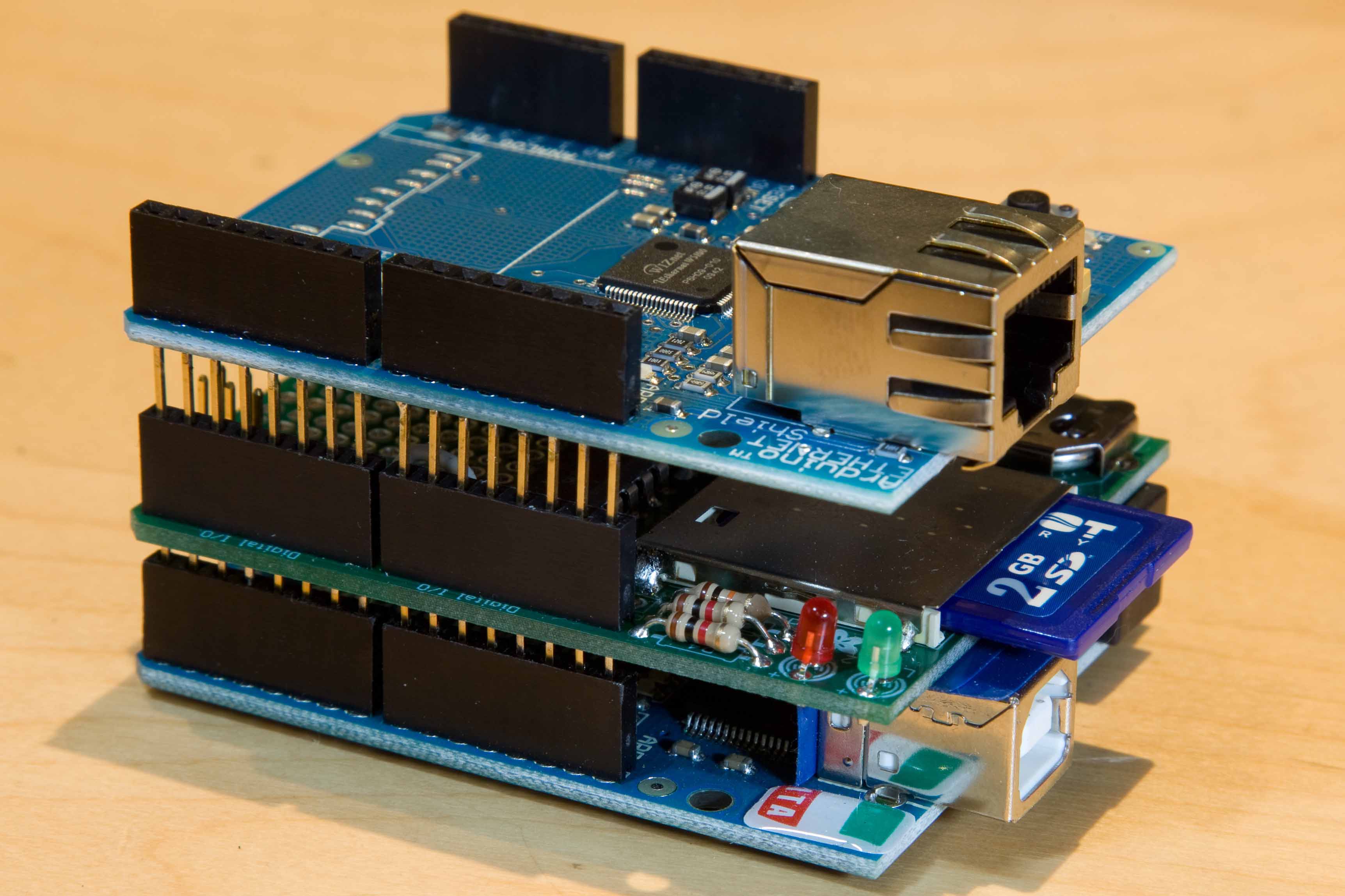
Connection and loading of programs into memory is carried out via a USB port. Connecting modules can be done in many ways - including the use of a special breadboard, jumpers, wires... It is not at all necessary to use a soldering iron. You can connect almost anything - any gadget can become a full-fledged part of your design! At the same time, you can also create multi-layer “sandwiches” from the so-called - additional fees, expanding the capabilities of the main chip. The main thing is the basic process at the heart of Uno itself, the rest only serves to provide additional capabilities. For example, this could be connecting to the Internet or controlling a powerful motor.
We use IDE
Those written for the Arduino platform are called sketches. You can create a sketch using an integrated development environment, or IDE for short (the official version is called that). Once you have installed the drivers and this environment, you can take your first step.
The IDE provides you with already written simple sketches. Open one of them and select your Arduino in the list of boards, then upload the sketch to your device using the Upload command. All this is done very simply - the interface of the development environment is graphical, it is intuitive.

There are also a huge number of ready-made sketches on the Internet. For example, on Wikipedia in the article about Arduino you can find ready-made example program that sets the LED to blink. On specialized resources you will find incredibly complex algorithms that make Arduino a real robot. To learn how to write such, you will need certain time and perseverance, but you can study them at the very beginning to understand as many principles of programming for the platform as possible. If you want to write a basic program and don’t know how, then .
Best regards, Gridin Semyon
A series of articles and training diagrams with amateur radio experiments on Arduino for beginners. This is such an amateur radio construction toy, from which, without a soldering iron, etching of printed circuit boards and the like, any electronics kettle can assemble a full-fledged working device, suitable for both professional prototyping and amateur experiments in the study of electronics.
The Arduino board is intended primarily for teaching novice radio amateurs the basics of programming microcontrollers and creating microcontroller devices with their own hands without serious theoretical training. Wednesday Arduino development allows you to compile and load ready-made program code into the board’s memory. Moreover, loading the code is extremely simple.
Arduino where to start for a beginner |
First of all, to work with the Arduino board, a novice electronics engineer needs to download the Arduino development program; it consists of a built-in text editor in which we work with program code, a message area, a text output window (console), a toolbar with buttons for frequently used commands and several menus. To download your programs and communicate, this program is through a standard USB cord connects to the Arduino board.

Code written in the Arduino environment is called sketch. It is written in a text editor that has special tools for inserting/cutting, replacing/searching text. During saving and exporting, explanations appear in the message area (see the picture in the first lesson for beginners, just below), and errors may also be displayed. The console shows Arduino messages including full error reports and other useful information. Toolbar buttons allow you to check and record a sketch, open, create and save it, open serial bus monitoring, and much more.
So let's move on to the first one. Arduino lesson circuit diagrams for beginner electronics engineers.
Controller Arduino UNO for the convenience of beginners, it already has a resistance and an LED connected to pin 13 of the connector, so we don’t need any external radio elements in the first experiment.

By loading the code, Arduino allows our program to participate in system initialization. To do this, we indicate to the microcontroller commands that it will execute at the time of initial boot and then completely forget about them (i.e., these commands will be executed by the Arduino only once at startup). And it is for this purpose that in our code we select a block in which these commands are stored. void setup(), or rather in the space inside the curly braces of this function, see the program sketch.
Don't forget the curly braces! The loss of at least one of them will make the entire sketch completely unworkable. But don’t put extra parentheses either, as this will also cause an error.
| Download code:
|

Function void loop() this is where we put the commands that will be executed as long as the Arduino is turned on. Having started execution from the first command, the Arduino will reach the very end and immediately go to the beginning to repeat the same sequence. And so on an infinite number of times, as long as the board receives power. At its core, a void loop is the main function, the entry point into Arduino.
Function delay(1000) delays program processing by 1000 milliseconds. It all goes on in an eternal cycle loop().
The main conclusion after understanding our first program on Arduino: Using the void loop and void setup functions, we pass our instructions to the microcontroller. Everything that is inside the setup block will be executed only once. The contents of the loop module will be repeated in a loop as long as the Arduino remains turned on.
In the previous program there was a second delay between turning the LED on and off. There was one big minus in the simplest code of a novice Arduino operator used above. To maintain a pause between turning on and off the LED for one second, we used the function delay() and therefore at this moment the controller is not able to execute other commands in the main function loop(). Correcting code in a function loop(), presented below solves this problem.
Instead of setting the value to HIGH and then to LOW, we will get the value of ledPin and invert it. Let’s say if it was HIGH, it will become LOW, etc.

Second Arduino code option for LED control Here:
Then you can replace the function delay(). Instead, it is better to use the function millis(). It returns the number of milliseconds that have passed since the program started. The function will overflow after approximately 50 days of running the program code.
A similar function is micros(), which returns the number of microseconds that have passed since the program code was launched. The function will return to zero after 70 minutes of program operation.
Of course, this will add a few lines of code to our sketch, but it will undoubtedly make you a more experienced programmer and increase the potential of your Arduino. To do this, you just need to learn how to use the millis function.
It should be clearly understood that simplest function delay pauses the execution of the entire Arduino program, making it unable to perform any tasks during that period of time. Instead of pausing our entire program, we can count how much time has passed before the action completes. This, nicely, is implemented using the millis() function. To make everything easy to understand, we will consider the following option for flashing an LED without a time delay.
The beginning of this program is the same as any other standard Arduino sketch.

This example uses two Arduino digital I/O pins. The LED is connected to pin 8, which is configured as OUTPUT. A button is connected to 9 via, which is configured as INPUT. When we press the button, pin 9 is set to HIGH, and the program switches pin 8 to HIGH, thereby turning on the LED. Releasing the button resets pin 9 to LOW. The code then switches pin 8 to LOW, turning off the indicator light.
To control five LEDs we will use various manipulations with Arduino ports. To do this, we will directly write data to the Arduino ports, this will allow us to set the values for the LEDs using just one function.
Arduino UNO has three ports: B(digital inputs/outputs from 8 to 13); C(analog inputs); D(digital inputs/outputs 0 to 7)
Each port controls three registers. The first DDR defines what it will be pin input or exit. Using the second PORT register, you can set pin to HIGH or LOW. Using the third, you can read information about the state of the Arduino legs, if they work as an input.

To operate the circuit, we will use port B. To do this, we will set all port pins as digital outputs. Port B has only 6 legs. The DDRB register bits must be set to "1" , if the pin will be used as an output (OUTPUT), and in "0" , if we plan to use the pin as an input (INPUT). Port bits are numbered 0 to 7, but do not always have all 8 pins
Let's say: DDRB = B00111110;// set port B pins 1 to 5 as output and 0 as input.
In our running lights circuit we use five outputs: DDRB = B00011111; // set port B pins 0 to 4 as outputs.
To write data to port B, you need to use the PORTB register. You can light the first LED using the control command: PORTB = B00000001;, first and fourth LED: PORTB = B00001001 etc.
There are two binary shift operators: left and right. The left shift operator causes all data bits to move to the left, while the right shift operator moves them to the right.
Example:
varA = 1; // 00000001
varA = 1 varA = 1 varA = 1
Now let's return to the source code of our program. We need to enter two variables: upDown will include the values of where to move - up or down, and the second cylon will indicate which LEDs to light.
Structurally, such an LED has one general conclusion and three pins for each color. Below is a diagram of connecting an RGB LED to an Arduino board with a common cathode. All resistors used in the connection circuit must be of the same value from 220-270 Ohms.

For a connection with a common cathode, the connection diagram for a three-color LED will be almost the same, except that the common pin will be connected not to ground (gnd on the device), but to the +5 volt pin. Pins Red, green and blue in both cases are connected to the controller digital outputs 9, 10 and 11.
We will connect an external LED to the ninth pin of Arduino UNO through a resistance of 220 Ohms. To smoothly control the brightness of the latter, use the function analogWrite(). It provides output of a PWM signal to the controller leg. Moreover, the team pinMode() no need to call. Because analogWrite(pin,value) includes two parameters: pin - pin number for output, value - value from 0 to 255.
Code:
/*
A tutorial example for a novice Arduino developer that reveals the capabilities of the analogWrite() command for implementing the Fade effect of an LED
*/
int brightness = 0; // LED brightness
int fadeAmount = 5; // brightness change step
unsigned long currentTime;
unsigned long loopTime;
Void setup() (
pinMode(9, OUTPUT); // set pin 9 as output
currentTime = millis();
loopTime = currentTime;
}
Void loop() (
currentTime = millis();
if(currentTime >= (loopTime + 20))(
analogWrite(9, brightness); // set the value on pin 9
Brightness = brightness + fadeAmount; // add a step for changing the brightness, which will be established in the next cycle
// if reached min. or max. values, then we go in the opposite direction (reverse):
if (brightness == 0 || brightness == 255) (
fadeAmount = -fadeAmount ;
}
loopTime = currentTime;
}
}
Working Arduino with an encoder |
The encoder is designed to convert the angle of rotation into electrical signal. From it we receive two signals (A and B), which are opposite in phase. In this tutorial, we will use the SparkFun COM-09117 encoder, which has twelve positions per revolution (each position is exactly 30°). The figure below clearly shows how output A and B depend on each other when the encoder moves clockwise or counterclockwise.

If signal A goes from a positive level to zero, we read the value of output B. If output B is in a positive state at this point in time, then the encoder moves in a clockwise direction, if B outputs a zero level, then the encoder moves in the opposite direction. By reading both outputs, we are able to calculate the direction of rotation using a microcontroller, and by counting pulses from the A output of the encoder, the angle of rotation.
If necessary, you can use frequency calculations to determine how fast the encoder rotates.
Using an encoder in our tutorial example, we will adjust the brightness of the LED using the PWM output. To read data from the encoder, we will use a method based on software timers, which we have already covered.
Considering the fact that in the fastest case, we can rotate the encoder knob 180° in 1/10 of a second, this would be 6 pulses in 1/10 of a second or 60 pulses in one second.
In reality, it is not possible to rotate faster. Since we need to track all half-cycles, the frequency should be about 120 Hertz. To be completely sure, let's take 200 Hz.
Since, in this case, we are using a mechanical encoder, contact bounce is possible, and low frequency perfectly filters out such chatter.

Using program timer signals, it is necessary to constantly compare the current value of the encoder output A with the previous value. If the state changes from positive to zero, then we poll the state of output B. Depending on the result of the state poll, we increase or decrease the brightness value counter LED. The program code with a time interval of about 5 ms (200 Hz) is presented below:
Arduino beginner code:
/*
** Encoder
** To control the brightness of the LED, an encoder from Sparkfun is used
*/
Int brightness = 120; // LED brightness, start at half
int fadeAmount = 10; // brightness change step
unsigned long currentTime;
unsigned long loopTime;
const int pin_A = 12; // pin 12
const int pin_B = 11; // pin 11
unsigned char encoder_A;
unsigned char encoder_B;
unsigned char encoder_A_prev=0;
void setup() (
// declare pin 9 to be an output:
pinMode(9, OUTPUT); // set pin 9 as output
pinMode(pin_A, INPUT);
pinMode(pin_B, INPUT);
currentTime = millis();
loopTime = currentTime;
}
void loop() (
currentTime = millis();
if(currentTime >= (loopTime + 5))( // check states every 5ms (frequency 200 Hz)
encoder_A = digitalRead(pin_A); // read the state of output A of the encoder
encoder_B = digitalRead(pin_B); // encoder output B
if((!encoder_A) && (encoder_A_prev))( // if the state changes from positive to zero
if(encoder_B) (
// output B is in a positive state, which means the rotation is clockwise
// increase the brightness of the glow, no more than 255
if(brightness + fadeAmount )
else(
// output B is in the zero state, which means the rotation is counterclockwise
// reduce the brightness, but not below zero
if(brightness - fadeAmount >= 0) brightness -= fadeAmount;
}
}
encoder_A_prev = encoder_A; // save the value of A for the next loop
AnalogWrite(9, brightness); // set the brightness to the ninth pin
LoopTime = currentTime;
}
}
In this beginner's example, we'll look at working with a piezo emitter to generate sounds. To do this, let's take a piezoelectric sensor that allows us to generate sound waves in the frequency range 20 Hz - 20 kHz.
This is an amateur radio design where LEDs are located throughout the entire volume. Using this scheme, you can generate various lighting and animation effects. Complex circuits are even capable of displaying various three-dimensional words. In other words, this is an elementary surround monitor
The servo drive is the main element in the design of various radio-controlled models, and its control using a controller is simple and convenient.

The control program is simple and intuitive. It starts with connecting a file containing all the necessary commands to control the servo drive. Next, we create a servo object, for example servoMain. Next function setup(), in which we specify that the servo is connected to the ninth pin of the controller.
Code:
/*
Arduino Servo
*/
#include
Servo servoMain; // Servo object
Void setup()
{
servoMain.attach(9); // Servo connected to pin 9
}
void loop()
{
servoMain.write(45); // Rotate servo left 45°
delay(2000); // Wait 2000 milliseconds (2 seconds)
servoMain.write(0); // Rotate servo left by 0°
delay(1000); // Pause 1 s.
delay(1500); // Wait 1.5 s.
servoMain.write(135); // Rotate servo right 135°
delay(3000); // Pause 3 s.
servoMain.write(180); // Rotate servo right 180°
delay(1000); // Wait 1 s.
servoMain.write(90); // Rotate the servo 90°. Central position
delay(5000); // Pause 5 s.
}
In the main function loop(), we give commands to the servomotor, with pauses between them.
Arduino counter circuit on a 7-segment indicator |
This simple Arduino project for beginners involves creating a counter circuit using a regular 7-segment common-cathode display. Program code, given below, allows you to start counting from 0 to 9 when you press a button.
Seven-segment indicator - is a combination of 8 LEDs (the last one is responsible for the point) with a common cathode, which can be turned on in the desired sequence so that they create numbers. It should be noted that in this circuit, see the figure below, pins 3 and 8 are allocated to the cathode.

On the right is a table of correspondence between Arduino pins and LED indicator pins.
Code for this project:
byte numbers = (
B11111100, B01100000, B11011010, B11110010, B01100110,
B10110110, B10111110, B11100000, B11111110, B11100110
};
void setup() (
for(int i = 2; i pinMode(i, OUTPUT);
}
pinMode(9, INPUT);
}
int counter = 0;
bool go_by_switch = true;
int last_input_value = LOW;
void loop() (
if(go_by_switch) (
int switch_input_value = digitalRead(9);
if(last_input_value == LOW && switch_input_value == HIGH) (
}
last_input_value = switch_input_value;
) else (
delay(500);
counter = (counter + 1) % 10;
}
writeNumber(counter);
}
Void writeNumber(int number) (
if(number 9) (
return;
}
byte mask = numbers;
byte currentPinMask = B10000000;
for(int i = 2; i if(mask & currentPinMask) digitalWrite(i,HIGH);
else digitalWrite(i,LOW);
currentPinMask = currentPinMask >> 1;
}
}
You can significantly expand the potential of Arduino boards using additional modules, which can be connected to the PIN pins of almost any device. Consider the most popular and interesting expansion modules, or shields as they are also called.