How to make an adjustable power supply. DIY power supply
Somehow recently I came across a diagram on the Internet that was very simple block power supply with voltage regulation. The voltage could be adjusted from 1 Volt to 36 Volt, depending on the output voltage on the secondary winding of the transformer.
Take a close look at the LM317T in the circuit itself! The third leg (3) of the microcircuit is connected to capacitor C1, that is, the third leg is INPUT, and the second leg (2) is connected to capacitor C2 and a 200 Ohm resistor and is an OUTPUT.
Using a transformer, from a mains voltage of 220 Volts we get 25 Volts, no more. Less is possible, no more. Then we straighten the whole thing with a diode bridge and smooth out the ripples using capacitor C1. All this is described in detail in the article on how to obtain constant voltage from alternating voltage. And our most important trump card in the power supply is the highly stable voltage regulator LM317T chip. At the time of writing, the price of this chip was around 14 rubles. Even cheaper than a loaf of white bread.
Description of the chip
LM317T is a voltage regulator. If the transformer produces up to 27-28 volts on the secondary winding, then we can easily regulate the voltage from 1.2 to 37 volts, but I would not raise the bar to more than 25 volts at the transformer output.
The microcircuit can be executed in the TO-220 package:

or in D2 Pack housing

It can pass a maximum current of 1.5 Amps, which is enough to power your electronic gadgets without voltage drop. That is, we can output a voltage of 36 Volts with a current load of up to 1.5 Amps, and at the same time our microcircuit will still output 36 Volts - this, of course, is ideal. In reality, fractions of volts will drop, which is not very critical. At high current When under load, it is more advisable to place this microcircuit on a radiator.
In order to assemble the circuit, we will also need a variable resistor of 6.8 Kilo-Ohms, or even 10 Kilo-Ohms, as well as a constant resistor of 200 Ohms, preferably from 1 Watt. Well, we put a 100 µF capacitor at the output. Absolutely simple scheme!
Assembly in hardware
Previously, I had a very bad power supply with transistors. I thought, why not remake it? Here is the result ;-)
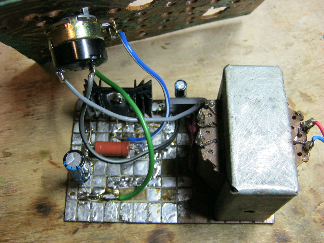
Here we see the imported GBU606 diode bridge. It is designed for a current of up to 6 Amps, which is more than enough for our power supply, since it will deliver a maximum of 1.5 Amps to the load. I installed the LM on the radiator using KPT-8 paste to improve heat transfer. Well, everything else, I think, is familiar to you.

And here is an antediluvian transformer that gives me a voltage of 12 volts on the secondary winding.

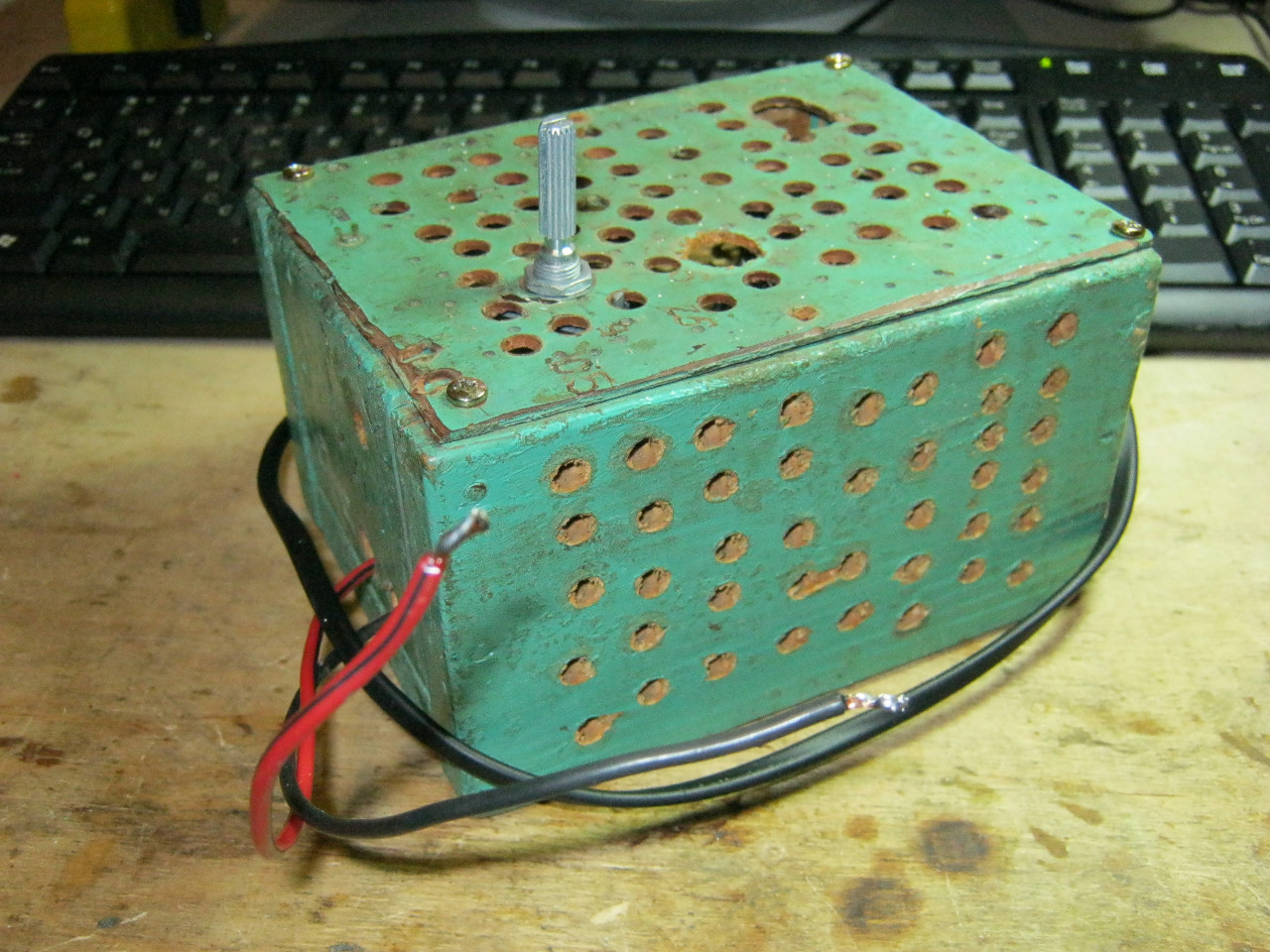
We carefully pack all this into the case and remove the wires.

How do you like it? ;-)
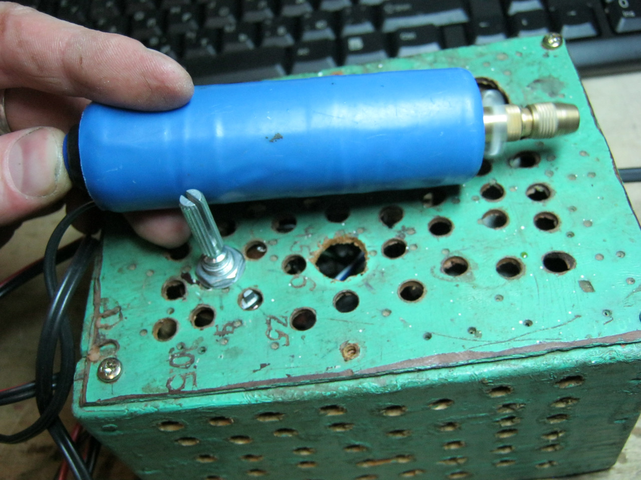
The minimum voltage I got was 1.25 Volts, and the maximum was 15 Volts.


I put any voltage in in this case the most common are 12 Volt and 5 Volt


Everything works great!
This power supply is very convenient for adjusting the speed of a mini drill, which is used for drilling circuit boards.
Analogues on Aliexpress
By the way, on Ali you can immediately find a ready-made set of this block without a transformer.

Too lazy to collect? You can buy a ready-made 5 Amp for less than $2:

You can view it at this link.
If 5 Amps is not enough, then you can look at 8 Amps. It will be enough for even the most seasoned electronics engineer:

Good laboratory block power supply is quite an expensive pleasure and not all radio amateurs can afford it.
Nevertheless, at home you can assemble a power supply with good characteristics, which can cope well with providing power to various amateur radio designs, and can also serve as a charger for various batteries.
Such power supplies are assembled by radio amateurs, usually from , which are available and cheap everywhere.
In this article, little attention is paid to the conversion of the ATX itself, since converting a computer power supply for a radio amateur of average qualification into a laboratory one, or for some other purpose, is usually not difficult, but beginning radio amateurs have many questions about this. Basically, what parts in the power supply need to be removed, what parts should be left, what should be added in order to turn such a power supply into an adjustable one, and so on.
Especially for such radio amateurs, in this article I want to talk in detail about converting ATX computer power supplies into regulated power supplies, which can be used both as a laboratory power supply and as a charger.
For the modification, we will need a working ATX power supply, which is made on a TL494 PWM controller or its analogues.
The power supply circuits on such controllers, in principle, do not differ much from each other and are all basically similar. The power of the power supply should not be less than that which you plan to remove from the converted unit in the future.
Let's take a look standard diagram ATX power supply, 250 W. For Codegen power supplies, the circuit is almost no different from this one.
The circuits of all such power supplies consist of a high-voltage and low-voltage part. In the picture of the power supply printed circuit board (below) from the side of the tracks, the high-voltage part is separated from the low-voltage part by a wide empty strip (without tracks), and is located on the right (it is smaller in size). We will not touch it, but will work only with the low-voltage part.
This is my board and using its example I will show you an option for converting an ATX power supply.

The low-voltage part of the circuit we are considering consists of a TL494 PWM controller, an operational amplifier circuit that controls the output voltages of the power supply, and if they do not match, it gives a signal to the 4th leg of the PWM controller to turn off the power supply.
Instead of operational amplifier transistors can be installed on the power supply board, which in principle perform the same function.
Next comes the rectifier part, which consists of various output voltages, 12 volts, +5 volts, -5 volts, +3.3 volts, of which for our purposes only a +12 volt rectifier will be needed (yellow output wires).
The remaining rectifiers and accompanying parts will need to be removed, except for the “duty” rectifier, which we will need to power the PWM controller and cooler.
The duty rectifier provides two voltages. Typically this is 5 volts and the second voltage can be around 10-20 volts (usually around 12).
We will use a second rectifier to power the PWM. A fan (cooler) is also connected to it.
If this output voltage is significantly higher than 12 volts, then the fan will need to be connected to this source through an additional resistor, as will be later in the circuits under consideration.
In the diagram below, I marked the high-voltage part with a green line, the “standby” rectifiers with a blue line, and everything else that needs to be removed with red.
So, we unsolder everything that is marked in red, and in our 12 volt rectifier we change the standard electrolytes (16 volts) to higher voltage ones, which will correspond to the future output voltage of our power supply. It will also be necessary to unsolder the 12th leg of the PWM controller and the middle part of the winding of the matching transformer - resistor R25 and diode D73 (if they are in the circuit) in the circuit, and instead of them solder a jumper into the board, which is drawn in the diagram with a blue line (you can simply close diode and resistor without soldering them). In some circuits this circuit may not exist.
Next, in the PWM harness on its first leg, we leave only one resistor, which goes to the +12 volt rectifier.
On the second and third legs of the PWM, we leave only the Master RC chain (in the diagram R48 C28).
On the fourth leg of the PWM we leave only one resistor (in the diagram it is designated as R49. Yes, in many other circuits between the 4th leg and the 13-14 legs of the PWM there is usually an electrolytic capacitor, we don’t touch it (if any) either, since it is intended for a soft start of the power supply. My board simply did not have it, so I installed it.
Its capacity in standard circuits is 1-10 μF.
Then we free the 13-14 legs from all connections, except for the connection with the capacitor, and also free the 15th and 16th legs of the PWM.
After all the operations performed, we should get the following.
This is what it looks like on my board (in the picture below).
Here I rewound the group stabilization choke with a 1.3-1.6 mm wire in one layer on the original core. It fit somewhere around 20 turns, but you don’t have to do this and leave the one that was there. Everything works well with him too.
I also installed another load resistor on the board, which consists of two 1.2 kOhm 3W resistors connected in parallel, the total resistance was 560 Ohms.
The native load resistor is designed for 12 volts of output voltage and has a resistance of 270 Ohms. My output voltage will be about 40 volts, so I installed such a resistor.
It needs to be calculated (at the maximum output voltage of the power supply at idling) for a load current of 50-60 mA. Since operating the power supply completely without load is not desirable, that’s why it is placed in the circuit.

View of the board from the parts side.
Now what will we need to add to the prepared board of our power supply in order to turn it into an regulated power supply;
First of all, in order not to burn the power transistors, we will need to solve the problem of load current stabilization and protection from short circuit.
On forums for remaking similar blocks, I came across such an interesting thing - when experimenting with the current stabilization mode, on the forum pro-radio, forum member DWD I cited the following quote, I will quote it in full:
"I once told you that I couldn't get normal work The UPS is in current source mode with a low reference voltage at one of the inputs of the error amplifier of the PWM controller.
More than 50mV is normal, but less is not. In principle, 50mV is a guaranteed result, but in principle, you can get 25mV if you try. Anything less didn’t work. It does not work stably and is excited or confused by interference. This is when the signal voltage from the current sensor is positive.
But in the datasheet on the TL494 there is an option when negative voltage is removed from the current sensor.
I converted the circuit to this option and got an excellent result.
Here is a fragment of the diagram.

Actually, everything is standard, except for two points.
Firstly, better stability When the load current stabilizes with a negative signal from the current sensor, is this an accident or a pattern?
The circuit works great with a reference voltage of 5mV!
With a positive signal from the current sensor stable work is obtained only at higher reference voltages (at least 25 mV).
With resistor values of 10Ohm and 10KOhm, the current stabilized at 1.5A up to the output short circuit.
I need more current, so I installed a 30 Ohm resistor. Stabilization was achieved at a level of 12...13A at a reference voltage of 15mV.
Secondly (and most interestingly), I don’t have a current sensor as such...
Its role is played by a fragment of a track on the board 3 cm long and 1 cm wide. The track is covered with a thin layer of solder.
If you use this track at a length of 2cm as a sensor, then the current will stabilize at the level of 12-13A, and if at a length of 2.5cm, then at the level of 10A."
Since this result turned out to be better than the standard one, we will go the same way.
First, you will need to unsolder the middle terminal of the secondary winding of the transformer (flexible braid) from the negative wire, or better without soldering it (if the signet allows) - cut the printed track on the board that connects it to the negative wire.
Next, you will need to solder a current sensor (shunt) between the track cut, which will connect the middle terminal of the winding to the negative wire.
It is best to take shunts from faulty (if you find them) pointer ampere-voltmeters (tseshek), or from Chinese pointer or digital instruments. They look something like this. A piece 1.5-2.0 cm long will be sufficient.

You can, of course, try to do it as I wrote above. DWD, that is, if the path from the braid to the common wire is long enough, then try to use it as a current sensor, but I didn’t do this, I came across a board of a different design, like this one, where the two wire jumpers that connected the output are indicated by a red arrow braids with a common wire, and printed tracks ran between them.

Therefore, after removing unnecessary parts from the board, I removed these jumpers and in their place soldered a current sensor from a faulty Chinese "tseshka".
Then I soldered the rewound inductor in place, installed the electrolyte and load resistor.
This is what my piece of board looks like, where I marked with a red arrow the installed current sensor (shunt) in place of the jumper wire.

Then you need to connect this shunt to the PWM using a separate wire. From the side of the braid - with the 15th PWM leg through a 10 Ohm resistor, and connect the 16th PWM leg to the common wire.
Using a 10 Ohm resistor, you can select the maximum output current of our power supply. On the diagram DWD The resistor is 30 ohms, but start with 10 ohms for now. Increasing the value of this resistor increases the maximum output current of the power supply.
As I said earlier, the output voltage of my power supply is about 40 volts. To do this, I rewound the transformer, but in principle you can not rewind it, but increase the output voltage in another way, but for me this method turned out to be more convenient.
I’ll tell you about all this a little later, but for now let’s continue and start installing the necessary additional parts on the board so that we have a working power supply or charger.
Let me remind you once again that if you did not have a capacitor on the board between the 4th and 13-14 legs of the PWM (as in my case), then it is advisable to add it to the circuit.
You will also need to install two variable resistors (3.3-47 kOhm) to adjust the output voltage (V) and current (I) and connect them to the circuit below. It is advisable to make the connection wires as short as possible.
Below I have given only part of the diagram that we need - such a diagram will be easier to understand.
In the diagram, newly installed parts are indicated in green.

Diagram of newly installed parts.
Let me give you a little explanation of the diagram;
- The topmost rectifier is the duty room.
- The values of the variable resistors are shown as 3.3 and 10 kOhm - the values are as found.
- The value of resistor R1 is indicated as 270 Ohms - it is selected according to the required current limitation. Start small and you may end up with a completely different value, for example 27 Ohms;
- I did not mark capacitor C3 as a newly installed part in the expectation that it might be present on the board;
- The orange line indicates elements that may have to be selected or added to the circuit during the process of setting up the power supply.
Next we deal with the remaining 12-volt rectifier.
Let's check what maximum voltage our power supply can produce.
To do this, we temporarily unsolder from the first leg of the PWM - a resistor that goes to the output of the rectifier (according to the diagram above at 24 kOhm), then you need to turn on the unit to the network, first connect it to the break of any network wire, and use a regular 75-95 incandescent lamp as a fuse Tue In this case, the power supply will give us the maximum voltage it is capable of.
Before connecting the power supply to the network, make sure that the electrolytic capacitors in the output rectifier are replaced with higher voltage ones!
All further switching on of the power supply should be carried out only with an incandescent lamp; it will protect the power supply from emergency situations in case of any errors. In this case, the lamp will simply light up, and the power transistors will remain intact.
Next we need to fix (limit) the maximum output voltage of our power supply.
To do this, we temporarily change the 24 kOhm resistor (according to the diagram above) from the first leg of the PWM to a tuning resistor, for example 100 kOhm, and set it to the maximum voltage we need. It is advisable to set it so that it is 10-15 percent less than maximum voltage, which our power supply is capable of producing. Then solder a permanent resistor in place of the tuning resistor.
If you plan to use this power supply as a charger, then the standard diode assembly used in this rectifier can be left, since its reverse voltage is 40 volts and it is quite suitable for a charger.
Then the maximum output voltage of the future charger will need to be limited in the manner described above, around 15-16 volts. For a 12-volt battery charger, this is quite enough and there is no need to increase this threshold.
If you plan to use your converted power supply as adjustable block power supply, where the output voltage will be more than 20 volts, then this assembly will no longer be suitable. It will need to be replaced with a higher voltage one with the appropriate load current.
I installed two assemblies on my board in parallel, 16 amperes and 200 volts each.
When designing a rectifier using such assemblies, the maximum output voltage of the future power supply can be from 16 to 30-32 volts. It all depends on the model of the power supply.
If, when checking the power supply for the maximum output voltage, the power supply produces a voltage less than planned, and someone needs more output voltage (40-50 volts for example), then instead of the diode assembly, you will need to assemble a diode bridge, unsolder the braid from its place and leave it hanging in the air, and connect the negative terminal of the diode bridge in place of the soldered braid.

Rectifier circuit with diode bridge.
With a diode bridge, the output voltage of the power supply will be twice as high.
Diodes KD213 (with any letter) are very suitable for a diode bridge, the output current with which can reach up to 10 amperes, KD2999A,B (up to 20 amperes) and KD2997A,B (up to 30 amperes). The last ones are best, of course.
They all look like this;

In this case, it will be necessary to think about attaching the diodes to the radiator and isolating them from each other.
But I took a different route - I simply rewound the transformer and did it as I said above. two diode assemblies in parallel, since there was space for this on the board. For me this path turned out to be easier.
Rewinding a transformer is not particularly difficult, and we’ll look at how to do it below.
First, we unsolder the transformer from the board and look at the board to see which pins the 12-volt windings are soldered to.

There are mainly two types. Just like in the photo.
Next you will need to disassemble the transformer. Of course, it will be easier to deal with smaller ones, but larger ones can also be dealt with.
To do this, you need to clean the core from visible varnish (glue) residues, take a small container, pour water into it, put the transformer there, put it on the stove, bring to a boil and “cook” our transformer for 20-30 minutes.

For smaller transformers this is quite enough (less is possible) and such a procedure will not harm the core and windings of the transformer at all.
Then, holding the transformer core with tweezers (you can do it right in the container), using a sharp knife we try to disconnect the ferrite jumper from the W-shaped core.

This is done quite easily, since the varnish softens from this procedure.
Then, just as carefully, we try to free the frame from the W-shaped core. This is also quite easy to do.

Then we wind up the windings. First comes half of the primary winding, mostly about 20 turns. We wind it up and remember the direction of winding. The second end of this winding does not need to be unsoldered from the point of its connection with the other half of the primary, if this does not interfere further work with transformer.

Then we wind up all the secondary ones. Usually there are 4 turns of both halves of 12-volt windings at once, then 3+3 turns of 5-volt windings. We wind everything up, unsolder it from the terminals and wind a new winding.
The new winding will contain 10+10 turns. We wind it with a wire with a diameter of 1.2 - 1.5 mm, or a set of thinner wires (easier to wind) of the appropriate cross-section.
We solder the beginning of the winding to one of the terminals to which the 12-volt winding was soldered, we wind 10 turns, the direction of winding does not matter, we bring the tap to the “braid” and in the same direction as we started - we wind another 10 turns and the end solder to the remaining pin.
Next, we isolate the secondary and wind the second half of the primary onto it, which we wound earlier, in the same direction as it was wound earlier.
We assemble the transformer, solder it into the board and check the operation of the power supply.
If any problems arise during the voltage adjustment process extraneous noise, squeaks, cods, then to get rid of them, you will need to pick up the RC chain circled in the orange ellipse below in the figure.

In some cases, you can completely remove the resistor and select a capacitor, but in others you can’t do it without a resistor. You can try adding a capacitor, or the same RC circuit, between 3 and 15 PWM legs.
If this does not help, then you need to install additional capacitors (circled in orange), their ratings are approximately 0.01 uF. If this doesn’t help much, then install an additional 4.7 kOhm resistor from the second leg of the PWM to the middle terminal of the voltage regulator (not shown in the diagram).
Then you will need to load the power supply output, for example, with a 60-watt car lamp, and try to regulate the current with resistor “I”.
If the current adjustment limit is small, then you need to increase the value of the resistor that comes from the shunt (10 Ohms) and try to regulate the current again.
You should not install a tuning resistor instead of this one; change its value only by installing another resistor with a higher or lower value.
It may happen that when the current increases, the incandescent lamp in the network wire circuit will light up. Then you need to reduce the current, turn off the power supply and return the resistor value to the previous value.
Also, for voltage and current regulators, it is best to try to purchase SP5-35 regulators, which come with wire and rigid leads.

This is an analogue of multi-turn resistors (only one and a half turns), the axis of which is combined with a smooth and coarse regulator. At first it is regulated “Smoothly”, then when it reaches the limit, it begins to be regulated “Roughly”.
Adjustment with such resistors is very convenient, fast and accurate, much better than with a multi-turn. But if you can’t get them, then buy ordinary multi-turn ones, such as;

Well, it seems like I told you everything that I planned to complete on remaking the computer power supply, and I hope that everything is clear and intelligible.
If anyone has any questions about the design of the power supply, ask them on the forum.
Good luck with your design!
Making a laboratory power supply with your own hands is not difficult if you have the skills to use a soldering iron and you understand electrical circuits. Depending on the parameters of the source, you can use it to charge batteries, connect almost any household equipment, and use it for experiments and design experiments. electronic means. The main thing during installation is the use of proven circuits and build quality. The more reliable the case and connections, the more convenient it is to work with the power source. It is desirable to have adjustments and devices for monitoring output current and voltage.
The simplest homemade power supply
If you do not have skills in making electrical appliances, then it is better to start with the simplest ones, gradually moving to complex designs. Composition of the simplest constant voltage source:
- Transformer with two windings (primary - for connecting to the network, secondary - for connecting consumers).
- One or four diodes for rectification AC.
- Electrolytic capacitor for cutting off the variable component of the output signal.
- Connecting wires.
If you use one semiconductor diode in the circuit, you will get a half-wave rectifier. If you use a diode assembly or a bridge circuit, then the power supply is called full-wave. The difference is in the output signal - in the second case there is less ripple.

Such homemade block power supply is good only in cases where it is necessary to connect devices with the same operating voltage. So, if you are designing automotive electronics or repairing them, it is better to choose a transformer with an output voltage of 12-14 volts. The output voltage depends on the number of turns of the secondary winding, and the current strength depends on the cross-section of the wire used (the greater the thickness, the greater the current).
How to make bipolar power supply?
Such a source is necessary to ensure the operation of some microcircuits (for example, power amplifiers and low frequencies). Distinguishes bipolar block The power supply has the following feature: at the output it has a negative pole, positive and common. To implement such a circuit, it is necessary to use a transformer, the secondary winding of which has a middle terminal (and the value of the alternating voltage between the middle and extreme ones must be the same). If there is no transformer that satisfies this condition, you can upgrade any one whose network winding is designed for 220 volts.

Remove the secondary winding, but first measure the voltage on it. Count the number of turns and divide by the voltage. The resulting number is the number of turns required to produce 1 volt. If you need to get a bipolar power supply with a voltage of 12 volts, you will need to wind two identical windings. Connect the beginning of one to the end of the second and connect this middle point to the common wire. The two terminals of the transformer must be connected to the diode assembly. The difference from a unipolar source is that you need to use 2 electrolytic capacitors connected in series, the middle point is connected to the device body.
Voltage regulation in a unipolar power supply
The task may not seem very simple, but you can make a regulated power supply by assembling a circuit from one or two semiconductor transistors. But you will need to install at least a voltmeter at the output to monitor the voltage. For this purpose, a dial indicator with an acceptable measurement range can be used. You can buy it cheap digital multimeter and adapt it to your needs. To do this, you will need to disassemble it, set the desired switch position using soldering (with a voltage range of 1-15 volts, it is required that the device can measure voltages up to 20 volts).

The regulated power supply can be connected to any electrical device. First, you only need to set the required voltage value so as not to damage the devices. The voltage is changed using a variable resistor. You have the right to choose its design yourself. It could even be a slide-type device, the main thing is to comply with the nominal resistance. To make the power supply convenient to use, you can install a variable resistor paired with a switch. This will get rid of the extra toggle switch and make it easier to turn off the equipment.
Voltage regulation in a bipolar source
This design will be more complicated, but it can be implemented quite quickly if all the necessary elements are available. Not everyone can make a simple laboratory power supply, and even a bipolar one with voltage regulation. The scheme is complicated by the fact that it requires installation not only semiconductor transistor, operating in switch mode, but also an operational amplifier, zener diodes. When soldering semiconductors, be careful: try not to heat them too much, because the range permissible temperatures they have very little. When overheated, the germanium and silicon crystals are destroyed, causing the device to stop functioning.

When making a laboratory power supply with your own hands, remember one important detail: the transistors must be mounted on an aluminum radiator. The more powerful the power source, the larger the radiator area should be. Pay special attention to the quality of soldering and wires. For low-power devices, thin wires can be used. But if the output current is large, then it is necessary to use wires with thick insulation and a large cross-sectional area. Your safety and ease of use of the device depend on the reliability of switching. Even a short circuit in the secondary circuit can cause a fire, so when manufacturing the power supply, care should be taken to protect it.
Retro style voltage regulation
Yes, this is exactly what you can call making adjustments in this way. To implement it, you need to rewind the secondary winding of the transformer and make several conclusions depending on what voltage step and range you need. For example, a 30V 10A lab power supply in 1 volt increments would have 30 pins. A switch must be installed between the rectifier and the transformer. It is unlikely that you will be able to find one with 30 positions, and if you do find it, its dimensions will be very large. It is clearly not suitable for installation in a small case, so it is better to use standard voltages for manufacturing - 5, 9, 12, 18, 24, 30 volts. This is quite enough for convenient use of the device in the home workshop.

To manufacture and calculate the secondary winding of the transformer you need to do the following:
- Determine what voltage is collected by one turn of the winding. For convenience, wind 10 turns, connect the transformer to the network and measure the voltage. Divide the resulting value by 10.
- Wind the secondary winding, having first disconnected the transformer from the network. If it turns out that one turn collects 0.5 V, then to get 5 V you need to tap from the 10th turn. And using a similar scheme, you make taps for the remaining standard voltage values.

Anyone can make such a laboratory power supply with their own hands, and most importantly, there is no need to solder a circuit with transistors. Connect the secondary winding leads to a switch so that the voltage values change from lower to higher. The central terminal of the switch is connected to the rectifier, the lower terminal of the transformer according to the diagram is supplied to the device body.
Features of switching power supplies

Such circuits are used in almost all modern devices - in phone chargers, in power supplies for computers and televisions, etc. Making a laboratory power supply, especially a switching one, turns out to be problematic: too many nuances need to be taken into account. Firstly, relatively complex circuit and a complex operating principle. Secondly, most of the device runs under high voltage, which is equal to that flowing in the network. Look at the main components of such a power supply (using the example of a computer):
- A network rectification unit designed to convert 220 volt alternating current into direct current.
- Inverter that converts DC voltage into signals rectangular shape With high frequency. This also includes a special pulse-type transformer, which reduces the voltage to power the PC components.
- Department responsible for correct work all elements of the power supply.
- An amplification stage designed to amplify PWM controller signals.
- Block for stabilization and rectification of output pulse voltage.

Similar nodes and elements are present in all pulsed sources nutrition.
Computer power supply
The cost of even a new power supply that is installed in computers is quite low. But you get a ready-made design; you don’t even have to make a chassis. One drawback is that the output has only standard voltage values (12 and 5 volts). But for a home laboratory this is quite enough. A lab power supply made from ATX is popular because there is no need to make major modifications. And the simpler the design, the better. But there are also “diseases” with such devices, but they can be cured quite simply.

Electrolytic capacitors often fail. Electrolyte leaks out of them, this can be seen even with the naked eye: a layer of this solution appears on the printed circuit board. It is gel-like or liquid, and over time it hardens and becomes hard. To repair a laboratory power supply from a computer power supply, you need to install new electrolytic capacitors. The second breakdown, which is much less common, is the breakdown of one or more semiconductor diodes. The symptom is a failure of the fuse mounted on the printed circuit board. To repair, you need to ring all the diodes installed in the bridge circuit.
Methods for protecting power supplies
The easiest way to protect yourself is to install fuses. You can use such a laboratory power supply with protection without fear that a fire will occur due to a short circuit. To implement this solution, you will need to install two fuses in the power supply circuit of the mains winding. They need to be taken at a voltage of 220 volts and a current of about 5 amperes for low-power devices. Suitable fuses must be installed at the output of the power supply. For example, when protecting a 12-volt output circuit, you can use fuses used in cars. The current value is selected based on maximum power consumer.

But it's a century outside high technology, and making protection using fuses is not very profitable from an economic point of view. It is necessary to replace the elements after each accidental touching of the power wires. As an option, install self-restoring fuses instead of conventional fuse links. But they have a small resource: they can serve faithfully for several years, or they can fail after 30-50 outages. But a 5A laboratory power supply, if assembled correctly, functions correctly and does not require additional devices protection. The elements cannot be called reliable, often household appliances becomes unusable due to the breakdown of such fuses. It is much more effective to use a relay circuit or a thyristor circuit. Triacs can also be used as an emergency shutdown device.
How to make a front panel?
Most of the work is designing the enclosure rather than assembling the electrical circuit. You will have to arm yourself with a drill, files, and if painting is necessary, you will also have to master painting. You can make a homemade power supply based on the case from some device. But if you have the opportunity to purchase sheet aluminum, then if you wish, you can make a beautiful chassis that will serve you for many years. To begin, draw a sketch in which you arrange all the structural elements. Pay special attention to the design of the front panel. It can be made of thin aluminum, only reinforced from the inside - screwed to aluminum corners, which are used to give greater rigidity to the structure.

The front panel must have holes for installing measuring instruments, LEDs (or incandescent lamps), terminals connected to the output of the power supply, and sockets for installing fuses (if this protection option is selected). If the appearance of the front panel is not very attractive, then it needs to be painted. To do this, degrease and clean the entire surface until shiny. Before starting painting, make all the necessary holes. Apply 2-3 layers of primer to the heated surface and let dry. Next, apply the same number of layers of paint. Varnish should be used as a finishing coat. As a result, a powerful laboratory power supply, thanks to the paint and the resulting shine, will look beautiful and attractive and will fit into the interior of any workshop.
How to make a chassis for a power supply?
Only a design that is completely made independently will look beautiful. But you can use anything as a material: from sheet aluminum to housings from personal computers. You just need to carefully think through the entire design so that unforeseen situations do not arise. If the output stages require additional cooling, then install a cooler for this purpose. It can work both constantly when the device is turned on, and in automatic mode. To implement the latter, it is best to use a simple microcontroller and a temperature sensor. The sensor monitors the temperature of the radiator, and the microcontroller contains the value at which it is necessary to turn on the air blowing. Even a 10A laboratory power supply, whose power is not small, will work stably with such a cooling system.

Airflow requires air from outside, so you will need to install a cooler and radiator on the rear wall of the power supply. To ensure chassis rigidity, use aluminum corners, from which you first form a “skeleton”, and then install the casing on it - plates made of the same aluminum. If possible, connect the corners by welding, this will increase strength. The lower part of the chassis must be strong, since it is mounted on power transformer. The higher the power, the larger the dimensions of the transformer, the greater its weight. As an example, we can compare a 30V 5A laboratory power supply and a similar design, but at 5 volts and a current of about 1 A. The latter will have much smaller dimensions and light weight.
There must be a layer of insulation between the electronic components and the housing. You need to do this exclusively for yourself, so that in the event of an accidental break in the wire inside the unit, it does not short out to the housing. Before installing the sheathing on the “skeleton”, insulate it. You can stick on thick cardboard or thick adhesive tape. The main thing is that the material does not conduct electricity. With this modification, security is improved. But the transformer can produce an unpleasant hum, which can be eliminated by fixing and gluing the core plates, as well as installing rubber pads between the body and chassis. But you will get the maximum effect only by combining these solutions.
Summing up
In conclusion, it is worth mentioning that all installation and testing work is carried out in the presence of life-threatening voltage. Therefore, you need to think about yourself; be sure to install automatic switches in the room, paired with protective shutdown devices. Even if you touch the phase, you will not receive an electric shock, since the protection will work.
When working with switching power supplies for computers, follow safety precautions. The electrolytic capacitors found in their design are for a long time after disconnection they are energized. For this reason, before starting repairs, discharge the capacitors by connecting their leads. Just don’t be alarmed by the spark; it will not harm you or the devices.

When making a laboratory power supply with your own hands, pay attention to all the little things. After all, the main thing for you is to ensure stable, safe and convenient operation. And this can only be achieved if all the little details are carefully thought out, and not only in electrical diagram, but also in the device body. Monitoring devices will not be superfluous in the design, so install them to have an idea of, for example, what current the device you assembled in your home laboratory consumes.
This power supply on the LM317 chip does not require any special knowledge for assembly, and after proper installation from serviceable parts, does not require adjustment. Despite its apparent simplicity, this unit is a reliable power source. digital devices and has built-in protection against overheating and overcurrent. The microcircuit inside itself has over twenty transistors and is a high-tech device, although from the outside it looks like an ordinary transistor.
The power supply of the circuit is designed for voltages up to 40 volts alternating current, and the output can be obtained from 1.2 to 30 volts of constant, stabilized voltage. Adjustment from minimum to maximum with a potentiometer occurs very smoothly, without jumps or dips. Output current up to 1.5 amperes. If the current consumption is not planned to exceed 250 milliamps, then a radiator is not needed. When consumed greater load, place the microcircuit on thermal conductive paste to a radiator with a total dissipation area of 350 - 400 or more square millimeters. The selection of a power transformer must be calculated based on the fact that the voltage at the input to the power supply should be 10 - 15% greater than what you plan to receive at the output. It is better to take the power of the supply transformer with a good margin, in order to avoid excessive overheating, and be sure to install a fuse at its input, selected according to the power, to protect against possible troubles.
To us, to make this desired device, you will need the following details:
- Chip LM317 or LM317T.
- Almost any rectifier assembly or four separate diodes with a current of at least 1 ampere each.
- Capacitor C1 from 1000 μF and higher with a voltage of 50 volts, it serves to smooth out voltage surges in the supply network and the larger its capacitance, the more stable the output voltage will be.
- C2 and C4 – 0.047 uF. There is a number 104 on the capacitor cap.
- C3 – 1 µF or more with a voltage of 50 volts. This capacitor can also be used with a larger capacity to increase the stability of the output voltage.
- D5 and D6 - diodes, for example 1N4007, or any others with a current of 1 ampere or more.
- R1 – potentiometer for 10 Kom. Any type, but always a good one, otherwise the output voltage will “jump”.
- R2 – 220 Ohm, power 0.25 – 0.5 watts.
Assembling an adjustable stabilized power supply
I assembled it on a regular breadboard without any etching. I like this method because of its simplicity. Thanks to it, the circuit can be assembled in a matter of minutes.


Checking the power supply
By rotating the variable resistor you can set the desired output voltage, which is very convenient.
Those beginners who are just starting to study electronics are in a hurry to build something supernatural, like microbugs for wiretapping, a laser cutter from a DVD drive, and so on... and so on... What about assembling a power supply with an adjustable output voltage? This power supply is an essential item in every electronics enthusiast's workshop.
Where to start assembling the power supply?
First, you need to decide on the required characteristics that the future power supply will satisfy. The main parameters of the power supply are the maximum current ( Imax), which it can supply to the load (powered device) and the output voltage ( U out), which will be at the output of the power supply. It’s also worth deciding what kind of power supply we need: adjustable or unregulated.
Regulated power supply is a power supply whose output voltage can be changed, for example, from 3 to 12 volts. If we need 5 volts - we turned the regulator knob - we got 5 volts at the output, we need 3 volts - we turned it again - we got 3 volts at the output.
An unregulated power supply is a power supply with a fixed output voltage - it cannot be changed. For example, the well-known and widely used “Electronics” power supply D2-27 is unregulated and has an output voltage of 12 volts. Also unregulated power supplies are all kinds of chargers for cell phones, adapters for modems and routers. All of them, as a rule, are designed for one output voltage: 5, 9, 10 or 12 volts.
It is clear that for a novice radio amateur it is the regulated power supply that is of greatest interest. They can power a huge amount of both homemade and industrial devices, designed for different supply voltages.
Next you need to decide on the power supply circuit. The circuit should be simple, easy to repeat by beginning radio amateurs. Here it is better to stick to a circuit with a conventional power transformer. Why? Because it is quite easy to find a suitable transformer both in the radio markets and in the old consumer electronics. Making a switching power supply is more difficult. For pulse block power supply, it is necessary to manufacture quite a lot of winding parts, such as a high-frequency transformer, filter chokes, etc. Also, switching power supplies contain more radio-electronic components than regular blocks power supply with power transformer.
So, the circuit of the regulated power supply proposed for repetition is shown in the picture (click to enlarge).

Power supply parameters:
Output voltage ( U out) – from 3.3...9 V;
Maximum load current ( Imax) – 0.5 A;
The maximum amplitude of output voltage ripple is 30 mV;
Overcurrent protection;
Protection against overvoltage at the output;
High efficiency.
It is possible to modify the power supply to increase the output voltage.
The circuit diagram of the power supply consists of three parts: a transformer, a rectifier and a stabilizer.
Transformer. Transformer T1 reduces the alternating mains voltage (220-250 volts), which is supplied to the primary winding of the transformer (I), to a voltage of 12-20 volts, which is removed from the secondary winding of the transformer (II). Also, “part-time”, the transformer serves as a galvanic isolation between the electrical network and the powered device. This is very important function. If the transformer suddenly fails for any reason (voltage surge, etc.), then the mains voltage will not be able to reach the secondary winding and, therefore, the powered device. As you know, the primary and secondary windings of a transformer are reliably isolated from each other. This circumstance reduces the risk of electric shock.
Rectifier. From the secondary winding of power transformer T1, reduced alternating voltage 12-20 volts goes to the rectifier. This is already a classic. The rectifier consists of a diode bridge VD1, which rectifies alternating voltage from the secondary winding of the transformer (II). To smooth out voltage ripples, after the rectifier bridge there is an electrolytic capacitor C3 with a capacity of 2200 microfarads.
Adjustable pulse stabilizer.
The pulse stabilizer circuit is assembled on a fairly well-known and accessible DC/DC converter microcircuit - MC34063.
To make it clear. The MC34063 chip is a specialized PWM controller designed for pulsed DC/DC converters. This chip is the core of the adjustable switching regulator used in this power supply.
The MC34063 chip is equipped with a protection unit against overload and short circuit in the load circuit. The output transistor built into the microcircuit is capable of delivering up to 1.5 amperes of current to the load. At the base specialized chip MC34063 can be assembled as step-up ( Step-Up), and downward ( Step-Down) DC/DC converters. It is also possible to build adjustable pulse stabilizers.
Features of pulse stabilizers.
By the way, switching stabilizers have more high efficiency compared to stabilizers based on KR142EN series microcircuits ( CRANKS), LM78xx, LM317, etc. And although power supplies based on these chips are very simple to assemble, they are less economical and require the installation of a cooling radiator.
The MC34063 chip does not require a cooling radiator. It is worth noting that this chip can quite often be found in devices that operate autonomously or use backup power. The use of a switching stabilizer increases the efficiency of the device, and, consequently, reduces power consumption from the battery or battery. Due to this it increases offline time operation of the device from a backup power source.
I think it’s now clear why a pulse stabilizer is good.
Parts and electronic components.
Now a little about the parts that will be required to assemble the power supply.

Power transformers TS-10-3M1 and TP114-163M
A TS-10-3M1 transformer with an output voltage of about 15 volts is also suitable. You can find a suitable transformer in radio parts stores and radio markets, the main thing is that it meets the specified parameters.
Chip MC34063 . The MC34063 is available in DIP-8 (PDIP-8) for conventional through-hole mount and SO-8 (SOIC-8) for surface mount. Naturally, in the SOIC-8 package the chip is smaller in size, and the distance between the pins is about 1.27 mm. Therefore, make printed circuit board for a microcircuit in a SOIC-8 package it is more difficult, especially for those who have only recently begun to master the technology of producing printed circuit boards. Therefore, it is better to take the MC34063 chip in a DIP package, which is larger in size, and the distance between the pins in such a package is 2.5 mm. It will be easier to make a printed circuit board for a DIP-8 housing.
Chokes. Chokes L1 and L2 can be made independently. To do this, you will need two ring magnetic cores made of 2000HM ferrite, size K17.5 x 8.2 x 5 mm. The standard size is deciphered as follows: 17.5 mm. – outer diameter of the ring; 8.2 mm. - internal diameter; a 5 mm. – height of the ring magnetic circuit. To wind the choke you will need a PEV-2 wire with a cross section of 0.56 mm. 40 turns of such wire must be wound on each ring. The turns of the wire should be distributed evenly over the ferrite ring. Before winding, the ferrite rings must be wrapped in varnished cloth. If you don’t have varnished fabric at hand, you can wrap the ring with three layers of tape. It is worth remembering that ferrite rings may already be painted - covered with a layer of paint. In this case, there is no need to wrap the rings with varnished cloth.
In addition to homemade chokes, you can also use ready-made ones. In this case, the process of assembling the power supply will speed up. For example, as chokes L1, L2 you can use the following surface-mount inductors (SMD - inductor).

As you can see, on the top of their case the inductance value is indicated - 331, which stands for 330 microhenry (330 μH). Also, ready-made chokes with radial leads for conventional installation in holes are suitable as L1, L2. This is what they look like.

The inductance value on them is marked either color code, or numeric. For the power supply, inductances marked 331 (i.e. 330 μH) are suitable. Taking into account the tolerance of ±20%, which is allowed for elements of household electrical equipment, chokes with an inductance of 264 - 396 μH are also suitable. Any inductor or inductor is designed for a certain D.C.. As a rule, it maximum value (I DC max) is indicated in the datasheet for the throttle itself. But this value is not indicated on the body itself. In this case, you can approximately determine the value of the maximum permissible current through the inductor based on the cross-section of the wire with which it is wound. As already mentioned, for self-made chokes L1, L2 require a wire with a cross section of 0.56 mm.
Throttle L3 is homemade. To make it, you need a magnetic core made of ferrite. 400HH or 600HH with a diameter of 10 mm. You can find this in antique radios. There it is used as a magnetic antenna. You need to break off a piece 11 mm long from the magnetic circuit. This is quite easy to do; ferrite breaks easily. You can simply tightly clamp the required section with pliers and break off the excess magnetic circuit. You can also clamp the magnetic core in a vice, and then sharply hit the magnetic core. If you fail to carefully break the magnetic circuit the first time, you can repeat the operation.
Then the resulting piece of magnetic circuit must be wrapped with a layer of paper tape or varnished cloth. Next, we wind 6 turns of PEV-2 wire folded in half with a cross-section of 0.56 mm onto the magnetic circuit. To prevent the wire from unwinding, wrap it with tape on top. Those wire leads from which winding of the inductor began are subsequently soldered into the circuit in the place where the points are shown in image L3. These points indicate the beginning of winding the coils with wire.
Additions.
Depending on your needs, you can make certain changes to the design.
For example, instead of a VD3 zener diode type 1N5348 (stabilization voltage - 11 volts), you can install a protective diode - a suppressor - in the circuit 1.5KE10CA.

A suppressor is a powerful protective diode, its functions are similar to a zener diode, however, its main role is in electronic circuits– protective. The purpose of the suppressor is to suppress high-voltage pulse noise. The suppressor has a high speed and is able to extinguish powerful impulses.
Unlike the 1N5348 zener diode, the 1.5KE10CA suppressor has high speed triggering, which will undoubtedly affect the performance of the protection.
In technical literature and among radio amateurs, a suppressor can be called differently: protective diode, limiting zener diode, TVS diode, voltage limiter, limiting diode. Suppressors can often be found in switching power supplies - there they serve as protection against overvoltage of the powered circuit in the event of faults in the switching power supply.
About the purpose and parameters protective diodes You can learn from the article about the suppressor.
Suppressor 1.5KE10 C A has a letter WITH in the name and is bidirectional - the polarity of its installation in the circuit does not matter.
If there is a need for a power supply with a fixed output voltage, then the variable resistor R2 is not installed, but replaced with a wire jumper. The required output voltage is selected using a constant resistor R3. Its resistance is calculated using the formula:
Uout = 1.25 * (1+R4/R3)
After the transformations, we obtain a formula that is more convenient for calculations:
R3 = (1.25 * R4)/(U out – 1.25)
If you use this formula, then for U out = 12 volts you will need a resistor R3 with a resistance of about 0.42 kOhm (420 Ohm). When calculating, the value of R4 is taken in kilo-ohms (3.6 kOhm). The result for resistor R3 is also obtained in kilo-ohms.
To more accurately set the output voltage U out, you can install a trimming resistor instead of R2 and set the required voltage using the voltmeter more accurately.
It should be taken into account that a zener diode or suppressor should be installed with a stabilization voltage 1...2 volts higher than the calculated output voltage ( U out) power supply. So, for a power supply with a maximum output voltage equal to, for example, 5 volts, a 1.5KE suppressor should be installed 6V8 CA or similar.
Manufacturing of printed circuit board.
A printed circuit board for the power supply can be made in different ways. Two methods for making printed circuit boards at home have already been discussed on the pages of the site.
The fastest and most comfortable way is to make a printed circuit board using a printed circuit board marker. A marker was used Edding 792. He showed himself at his best. By the way, the signet for this power supply was made with just this marker.
The second method is suitable for those who have a lot of patience and a steady hand. This is a technology for making a printed circuit board using a correction pencil. This is quite simple and accessible technology will be useful for those who could not find a marker for printed circuit boards, but do not know how to make boards with LUT or do not have a suitable printer.
The third method is similar to the second, only it uses tsaponlak - How to make a printed circuit board using tsaponlak?
In general, there is plenty to choose from.
Setting up and checking the power supply.
To check the functionality of the power supply, you first need to turn it on, of course. If there are no sparks, smoke or pops (this is quite possible), then the power supply is most likely working. At first, keep some distance from him. If you made a mistake when installing electrolytic capacitors or set them to a lower operating voltage, they can “pop” and explode. This is accompanied by electrolyte splashing in all directions through the protective valve on the body. So take your time. You can read more about electrolytic capacitors. Don’t be lazy to read this – it will come in handy more than once.
Attention! The power transformer is under high voltage during operation! Don't put your fingers near it! Don't forget about safety rules. If you need to change something in the circuit, then first completely disconnect the power supply from the mains, and then do it. There is no other way - be careful!
At the end of this whole story, I want to show you a finished power supply that I made with my own hands.

Yes, it does not yet have a housing, a voltmeter and other “goodies” that make it easier to work with such a device. But, despite this, it works and has already managed to burn out an awesome three-color flashing LED because of its stupid owner, who loves to twist the voltage regulator recklessly. I wish you, novice radio amateurs, to collect something similar!