Step by step bios setup. Setting up the BIOS to speed up your computer
After publishing a series of materials about overclocking computer components We began to receive questions from readers revealing ignorance of basic things related to setting up the BIOS of motherboards. We mentioned that you should approach overclocking already having initial theoretical knowledge in this area. However, apparently, many PC users are interested in getting a free performance boost (and more).
This material is intended to help beginners navigate the issues basic settings systems.
The article will discuss fairly simple concepts related to working with the configuration of motherboard firmware. To begin with, let's decipher the abbreviation BIOS - Basic Input/Output System (basic input/output system). This is a kind of software recorded in a chip with non-volatile memory, which allows you to initialize PC components and configure their operating modes. The BIOS contains the microcode needed to control the keyboard, video card, drives, ports, and other devices. For the average user, BIOS is identified with a visual shell that allows you to change computer settings if necessary.
We also note that the answers to most of the questions raised in this material can be found in the motherboard manuals. Alas, few users who want to know everything at once pay attention to the brochures supplied with these products. Sometimes the manuals are quite sparse, but nothing prevents you from familiarizing yourself with those devoted to other lines of boards from the same (or another) manufacturer - the basic BIOS options are standard, and what is applicable to one firmware is often suitable when working with another. Mastering this material is also facilitated by knowledge of the English language - a banal translation of terms will help you navigate the search for the necessary parameters.
What types of BIOS are there?
The differences in firmware come down not only to the abundance of settings and adjustment ranges of individual parameters. First of all, this is the microcode of a certain developer, which ultimately determines the visual shell. For example, the BIOS of ASUS motherboards is based on code from AMI (menu with blue symbols on gray background), most manufacturers use Award/Phoenix (blue background, yellow letters). Recently, extensible firmware interfaces EFI (Extensible Firmware Interface) have become widespread, distinguished by their extraordinary graphical interface. They allow navigation using not only the keyboard, but also the mouse, and menu items have become even more intuitive.
How to get into BIOS
To enter the BIOS, you must press the corresponding button on the keyboard while initializing PC devices (going through the POST procedure). If the motherboard firmware is based on microcode from AMI, it will be F2, Award - Del. In order to get into the BIOS of some laptops, you will need to activate the F8 key. However, even if you don’t know what microcode the board’s firmware is based on, during the device initialization process, a hint message will definitely appear on the screen (for example, Press F2 to Enter Setup - “Press F2 to get to the settings section”). If the monitor does not light up in time, after turning on the PC, regularly and often press the required button or, if you are not sure which one, try Del, then F2.
Selecting and changing firmware settings
BIOS settings are controlled exclusively from the keyboard. To move the cursor, use the arrow block (Up, Down, Right, Left). To change the desired parameter, highlight it with the cursor, press Enter and select one of the available modes. If the board's BIOS is based on microcode from AMI, you will have to use the “+” and “-” buttons for the same purposes. Setting specific values can be done directly from numeric keypad(for example, if you need to change the system bus frequency from 266 to 320 MHz, hover the cursor over the appropriate position, enter 3, 2, 0, then Enter). To go up one menu level, press the Esc key, exit the BIOS - perform a similar operation in the root directory. Often it also contains explanations of options for managing firmware settings. When exiting the BIOS using the Esc key (without saving the settings) or F10 (with saving the settings), a window will definitely appear asking Do you want to exit/save the settings? To confirm, press the Y (Yes) button, to cancel - N (No).
BIOS Basics in Pictures
 |
| The system is undergoing initialization procedure (POST). To get into the BIOS, in at the moment you need to press the Del key (this is indicated in the lower left part of the screen) |
 |
| The main BIOS menu of one of the motherboards manufactured by Gigabyte. Below are brief tips - descriptions of the purpose of individual keys |
 |
| The section devoted to fine-tuning the operating modes of the main system components (processor, RAM) can be called differently. IN in this case This MB Intelligent Tweaker(M.I.T.) |
 |
| Standard CMOS Features- a menu item available in the BIOS of any board. Allows you to set the date and time, as well as view a list of FDD, IDE and SATA devices connected to the system |
 |
| Advanced BIOS Features, or Options, is one of the most important sections related to system configuration. In our case, it is possible to control boot priority, individual CPU technologies and the visual design of the splash screen |
 |
| In the section Integrated Peripherals functional blocks implemented on the motherboard are activated (network card, audio codec, IEEE 1394, USB ports, IDE and SATA controllers), their operating modes are set |
 |
| Power Management Setup- control computer power, turn on/off without using a button Power system unit |
 |
| In subcategory PnP/PCI Configurations has nothing interesting for the average user. System addressing settings are hidden there |
 |
| System monitoring section - PC Health Status. Allows you to monitor the operating temperature of PC components, main supply voltages, and control the number of revolutions of system fans |
 |
| In this BIOS, control of parameters important for overclocking a PC is concentrated in one section. Things may be different with the settings of boards using firmware from AMI - similar options are sometimes placed in different subcategories of the main menu |
BIOS updates - is it worth doing?
By the time a certain motherboard model is announced, manufacturers do not always have time to develop optimal firmware for it. Therefore, over time, BIOS updates are released and available for download from the manufacturers’ official websites. A list of improvements that a particular firmware version has is often given in the description. Is it worth constantly updating? Motherboard BIOS fees? If the PC works well, and overclocking of components is not limited to the board, then there is no need to do this. The firmware should be changed only if there are significant changes in certain parameters, expansion of functionality, and sometimes the introduction of support for new processor models.
Information on how to update the firmware is also available on the manufacturers' websites. Owners of modern products do this directly from within the OS, using specialized utilities. To update the firmware of older boards, you need to get a disk drive. When upgrading the BIOS, be extremely careful - power loss, premature pressing of Reset button before the operation is completed, and the motherboard will have to be sent to a service center. There may be freezes caused by defects in utilities from manufacturers. So don’t overdo it in the pursuit of each new BIOS version, because good is not a good thing.
After changing the settings, the computer does not boot. What to do?
A typical situation that accompanies the activity of overclockers is the inability to boot a PC after setting incorrect parameters in the BIOS. On many modern motherboards Reset technologies have been implemented in such cases. However, they do not always work, and not all boards are equipped with them. But this is not a reason to get upset, panic and say that the computer is broken. Any motherboard has a special jumper to force all settings to be reset to Default mode, which is often designated as CLR_CMOS (or Clear CMOS). Its location must be indicated in the board's instruction manual. The jumper may take the form of a special button located on back panel(a similar solution is found in top ASUSTeK boards), or be soldered in the area where the battery is located. If it has three contacts, two of which are closed by a jumper (a similar circuit is used in most products), you need to move the jumper from one position to another for a few seconds while the computer is turned off (say, 1-2 → 2-3) and back. Sometimes a jumper has only two pins (common on Gigabyte boards), then they must be connected with a conductive object (for example, a screwdriver).
If, after resetting, the system goes through the POST initialization procedure, but does not boot into the OS, make sure that the hard drive is displayed in the BIOS and is listed as the first number among the available boot devices. When using an HDD with an IDE connector on modern motherboards, you will probably have to configure the operating mode of the external controller (Configure SATA Interface as IDE). After carrying out the described manipulations, the system should boot successfully, except in cases where the OS fails (such complications are possible, especially when playing for a long time with memory timing settings, but they occur extremely rarely).
Basic BIOS sections - where to look for what
It is absolutely not necessary for a novice user to thoroughly study every item of the firmware in order to configure the system. Therefore, we will briefly talk about the main features available in the BIOS of all boards.
From the basic sections we highlight Standard CMOS Features, Advanced BIOS Features And Integrated Peripherals. The first of them displays the current date and time, the amount of RAM, and displays a list of IDE- and SATA-compatible system devices. You can also change the clock parameters through the OS, so the value of this section lies in the initial diagnostics of the PC: it monitors which drives, hard drives are connected and determined at the hardware level and which are not. In Advanced BIOS Features (or Boot menu, if the firmware is based on code from AMI) the boot sequence priority is set. There are cases when the operating system on the HDD is not initialized only because the FDD containing the floppy disk or the CD-ROM with the boot disk is selected first in the list of devices. Until you remove the media, don't expect to see the OS. Immediately install the hard drive first - you will never go wrong. The Integrated Peripherals section is interesting because it allows you to disable controllers soldered on the motherboard, thus managing the functionality of the PC. If there is no sound in your system when the speakers are connected correctly, check whether the audio codec is activated (the submenu value should be Enabled or Auto). The situation is similar with network controller, IEEE 1394, etc. Pay attention to the paragraphs dedicated to USB. Be sure to activate the appropriate controller and enable USB keyboard and mouse support. Depending on the positioning of the motherboard and its features, the Advanced BIOS Features and Integrated Peripherals sections may contain different system settings. You should pay attention to a brief study of the settings proposed in them.
Of the sections available in the BIOS of most boards, we will also highlight the sections for system monitoring (PC Health Status), power management (Power Management Setup) and configuring data bus addresses (PnP/PCI Configurations). The last two are of no interest to most. The most valuable thing for the average user is the monitoring section, which displays the temperatures of the main PC components (CPU, chipset) and the current voltages supplied by the power supply, and also has the ability to control the fan speed. However, you should not trust these sensors unconditionally - their readings can be inaccurate.
Settings that determine the performance of the PC and the operating modes of the main components are located in one or more adjacent subsections of the BIOS. It is possible that they may not be there at all - don’t expect to find them on a cheap motherboard for office computer options for seriously increasing supply voltages, setting RAM timings, and controlling CPU parameters. We talked about the relevant points in more detail in the materials devoted to overclocking a PC, so we won’t dwell on them now.
Most of the parameters that can be changed through the BIOS can be installed directly in the OS using specialized utilities. However, this method is often inconvenient - every time you boot the computer you need to launch additional software and activate certain settings. When you reinstall the system, they will be lost. Therefore, if you want to be on friendly terms with your computer, you will have to study the motherboard BIOS.
Afterword
Perhaps this material does not describe all the nuances of working with the BIOS that beginners would like to know. However, do not be upset if you have not found the answer to your question - first of all, remember where the instruction manual for the motherboard is located, and carefully study the section on firmware. If there is no brochure or the description is too sparse, you can download an extended version from the official website of the motherboard manufacturer for a specific product, or simply search good guide from a third party manufacturer. It is likely that the settings mentioned there will be largely similar. If you are not sure, ask again on specialized forums of thematic resources, although we do not see anything wrong with studying the BIOS on your own by trial and error. The “magic” CLR_CMOS jumper for resetting settings is available on any board, and it is almost impossible to damage any component without radically changing the power parameters (for example, increasing the voltage on the processor by 80% of the nominal value).
If, after carefully examining the BIOS of the motherboard installed in your PC, it suddenly turns out that certain settings are missing, do not be upset. On Gigabyte products, to activate the section responsible for fine-tuning the memory subsystem and CPU operating mode, after entering the BIOS you need to press the key combination Ctrl+F1. In other cases, it is quite possible that some options really are not there. A similar situation is typical for budget motherboards. In their firmware, sections on fine tuning and power management of PC components are either very scarce or completely absent. However, it is likely that the required parameters can be changed from under the operating system using specialized utilities.
A few words must be said about the new interface - EFI - which will replace the classic BIOS. Undoubtedly, you will like the pleasant graphical shell individual users, however, the convenience of its implementation should be judged only by testing the corresponding products. In the meantime, experienced overclockers are quite satisfied with the available capabilities, in which a complete setup of the motherboard BIOS to optimize the parameters of all components and overclock the PC takes from several tens of seconds to a minute. Too fast? Not at all. Learn the basics of working with firmware configuration, expand your own knowledge, and it is possible that over time you yourself will become specialists in this field.
Good day.
You work on your computer, you work, and then... bam 😢, and you need to reinstall the system, or enable function keys, or disable USB ports, etc. You can't do without setting up the BIOS...
I touch on the BIOS topic quite often on the blog. (since a number of problems simply cannot be solved without configuring it at all!), but there is no general topic in which all the basic terms and parameters would be discussed.
That's how this article was born...
Note: BIOS settings are based on the example of a Lenovo B70 laptop.
Many parameters, names of sections and tabs will be similar to other brands and models of laptops. I think that collecting all the variety of brands and all possible versions in one article (or even a section of the site) is simply unrealistic...
How to enter BIOS
I believe that the first place to start this article is with the question of entering the BIOS (otherwise there will be nothing to configure).
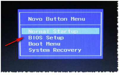
In most PC/laptop models, to enter the BIOS you need to press the button F2 or Del(sometimes F1 or Esc) immediately after turning on the device. Some laptops (for example, Lenovo) have a special button Recovery(which is pressed instead of the power button). After this, usually a sign appears (as in the photo below) - to configure the BIOS you need to select the item.
Control buttons
In the BIOS, all settings have to be set using the keyboard (which is somewhat scary for novice users who are used to doing everything with the mouse in Windows). It is also worth noting that all settings are set in English (however, most of the settings are easy enough to understand what they mean, even for those who have not studied English). And so, about the buttons...
I draw your attention to the fact that in almost every BIOS version, all the most basic control buttons with which it is configured are written at the bottom of the screen (or on the right).
Control buttons at the bottom of the window // Dell laptop Inspiron
Generally speaking, the buttons are as follows:
- arrows →↓← - used to move the cursor (change parameters);
- Enter - the main key for entering sections (as well as for selecting certain parameters and switching items);
- Esc - exit the BIOS without saving settings (or exit a specific partition);
- +/PgUp or -/PgDn - increase/decrease the numerical value of a certain parameter, or switch it;
- F1 - quick help (only for settings pages);
- F2 - hint for the selected item (not in all BIOS versions);
- F5/F6 - change the parameters of the selected item (in some BIOS versions they can also be used to restore changed settings);
- - save all changes in the BIOS and exit.
Important! In some laptops, in order for the function keys (F1, F2... F12) to work, you must press the combination of buttons Fn+F1, Fn+F2... Fn+F12. Typically, this information is always indicated at the bottom (right) of the window.
Sections and Tabs
The main tab in the laptop BIOS that you see when you log in. Allows you to get basic information about the laptop:
- its brand and model (see photo below: Product Name Lenovo B70-80). This information is extremely necessary, for example, when searching for drivers;
- BIOS version (if you decide to update the BIOS, this information will be extremely useful);
- the serial number of your device (not available everywhere, and the information is almost useless);
- processor model (CPU - Intel Core i3-5005U 2.00GHz);
- hard drive model;
- CD/DVD drive model and other information.

One of the main tabs for setting many parameters. On different laptops, the tab contains different settings, the main parameters include:
- System Time/Date- setting the date and time (often in Windows time gets confused, and sometimes it cannot be installed at all until the corresponding tab is configured in the BIOS);
- Wireless- Wi-Fi adapter, you can disable it here ( note: Enabled - on, Disabled - off). If you don't work with Wi-Fi networks- it is recommended to turn off the adapter, as it significantly consumes battery power (even when you are not connected to the Wi-Fi network);
- Sata Controller Mode- hard disk operating mode. This is quite a broad topic. Here I will say that the operation of your hard drive (for example, its operating speed) significantly depends on the selected parameter. If you don’t know what to set, then leave everything by default;
- Graphic Device Settings- a parameter that allows you to configure the operation of video cards (in laptops that have two video cards: integrated and discrete). In some cases (for example, when working with Windows XP, or when you want to save battery power as much as possible), you can disable the discrete video card here (note: there will likely be a performance hit in games);
- Power Beep- enable/disable the tweeter speaker. In my opinion, for a modern laptop in everyday use, this is a useless thing (it was relevant earlier, about 10 years ago);
- Intel Virtual Technology - hardware virtualization, which allows you to run several instances of operating systems (guest OS) on one physical computer. In general, not for novice users;
- BIOS Back Flash - if you want to update your old BIOS to a new version (i.e. flash it) - enable this option;
- HotKey Mode- operating mode of function keys. If the option is enabled: instead of the usual, say, F1-F12 to refresh a page in the browser or get help, you will be able to use multimedia capabilities - turn up or turn off sound, brightness, etc. To use the usual F1-F12 values, you need to press them together with the key Fn.

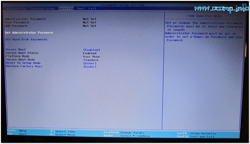
Tab for setting security (for some users this is one of the main ones). Here you can set an administrator password to access BIOS settings or to access the hard drive.
The main settings items in this section:
- Set Administrator Password - set an administrator password;
- Set Hard Dick Password - set a password to access the hard drive;
- Secure Boot -secure boot(on/off). By the way, Secure Boot is only displayed if you have the UEFI boot mode set.
Boot
Download section. It is also one of the most frequently used sections; it is almost always necessary for editing when installing Windows OS.
The boot mode is also set here: UEFI (new standard - for Windows 8/10), or the old boot method (Legacy, for Windows 7, XP). New items for editing the download queue will appear after saving the settings and entering this menu again!
Note: if support for the old mode is enabled, then you can (even need to!) change the boot priority from devices (for example, first check USB devices, then try to boot from CD/DVD, then from HDD).
Basic settings in this menu:
- Boot Mode : boot mode, UEFI or Legacy (the difference is described above);
- Fast Boot: Fast boot mode (the logo will not be shown, only built-in devices will be supported during boot: keyboard, display, etc.). Works only in Boot Mode: UEFI.
- USB Boot: Allow/prohibit booting from USB devices.
- PXE Boot to LAN: the option enables booting the computer over the network (initially an attempt will be made to load the operating system from the server using the local network. In my opinion, for most users, a useless function).

Note: It is worth noting that, in new version UEFI stopped working the ability to raise menu items using the F6 button, but the ability to lower another item with the F5 button remained.
Exit
I think everyone knows this word - it is translated from English as exit. This section is also used in almost all laptops (and PCs) to reset settings to optimal (or safe).
Key points:
- Exit Saving Changes- exit and save the changed settings in the BIOS;
- Exit Discarding Changes- exit BIOS without saving settings;
- Discard Changes- cancel all settings changes made during the current session;
- Save Changes- save settings changes;
- Load Defaults Changes- load the default BIOS settings (as they were when you purchased your laptop). Usually used in case unstable work device, or in cases where the user has changed something and no longer remembers...
- OS Optimized Defaults- settings optimized for specific OS (not all laptops have this option. It somewhat simplifies and speeds up BIOS setup).

How to choose which device to boot your laptop from (Boot Menu)
In order not to mess around with the BIOS settings and not to select (not set) the boot queue, it is very convenient to use the boot menu, calling it only when you need to boot from a flash drive (for example). I will provide a reference article on this topic here (link below).
Hotkeys to enter the BIOS menu, Boot Menu, restore from a hidden partition -
By calling the Boot Menu, you will see the usual list of devices from which you can boot. Most often this list contains (example in the photo below):
- hard drive;
- USB flash drive, disk;
- ability to boot over the network (LAN).

To select a device to boot, use the arrows and the Enter key. In general, the same as with normal BIOS setup.
This concludes the article.
And if you recklessly switch its parameters, the system will not start until it is successfully reset. The mistakes that programmers make when compiling it lead to annoying glitches and incompatibilities, but as they are eliminated, it is updated and is quite amenable to flashing - just make sure that the electrical power does not disappear during this, otherwise there will be trouble. Our hero is an important person, he is called BIOS. And its full title is: Basic Input-Output System, which translates as “basic input-output system.”
What is it and why
BIOS is a small program written on an EEPROM (Electrically Erasable Programmable Read-Only Memory) memory chip or flash memory, which is about the same thing. The motherboard BIOS is the first software that the computer uses immediately after turning it on. Its task is to identify devices (processor, memory, video, disks, etc.), check their serviceability, initiate, that is, start, with certain parameters and then transfer control to the operating system loader.
In fact, BIOS is found not only on the motherboard, but also on other components of the computer - even network adapters. However, we decided that the hero of our article should be the “mother” BIOS, because it is the one that users most often manipulate.
So, the PC owner can control the behavior of the BIOS within fairly wide limits. First of all, you can reflash it, that is, erase the contents of the microcircuit, and then write a new one. This feature is used to update the BIOS code. New firmware versions eliminate errors made by developers and introduce adequate support for new devices (for example, new processor models or RAM).
The second way to intervene in the BIOS is less drastic, but gives the user a huge number of options. This is a change in the parameters that are set to the hardware when the system starts. They are stored in volatile CMOS memory (there is a battery on the motherboard to save these settings). In order to change these settings, you need to press a certain button when the system starts - which one the computer will write (for example: “Press Del to enter Setup”), after which the inscription “Entering Setup...” appears, and then the BIOS control interface. And it is its detailed description that the rest of the article is devoted to.
The BIOS of all common motherboards are based on code written by one of two companies: American Management, Inc. (AMI) or Award. They are slightly different from each other, but generally similar. We will be looking at AMIBIOS. Once you understand it, you can easily navigate AwardBIOS.
Since considering a “spherical BIOS in a vacuum” is not particularly practical (it will be more difficult to explain what’s what), for example, let’s take the ASUS Rampage II Extreme motherboard for Core i7 processors in the LGA 1366 version. Its choice is primarily due to its very rich functionality. Having delved into its settings, the reader will be ready to meet even the most sophisticated motherboards - there is hardly anything unfamiliar in their BIOS. However, some nuances specific to this platform will be noted and explained in more detail. Let's go.
How to configure the BIOS correctly?
After the computer starts, the BIOS begins the Power-On Self Test (POST). During this time, the motherboard shows the user the manufacturer’s logo or data on the completion of the equipment test (depending on the current settings). At the bottom of the screen at this time it is written how to enter the BIOS setup interface and, just in case, how to call the BIOS flashing utility (it is available in the BIOS of the vast majority of relatively modern motherboards, starting with the Socket A platform, and allows you to update the microcode without loading the OS) .
In this case, entering the BIOS is done by pressing Del. In this case, the computer will write that it is entering the setup interface, and then display it. In the case of AMIBIOS, the main part of the screen will be occupied by the already open Main tab, in which the most basic system parameters can be configured. To move to another tab, use the left and right arrows. A list of tabs indicating which one is currently active is displayed at the top as a menu bar.
The contents of the Main tab, like the others, are divided vertically into two fields of unequal size. The left one contains settings that can be changed and sometimes additional diagnostic information. The item where the cursor is positioned is highlighted in white by default. Contextual hints in English are displayed in the right field - they help you quickly get used to the interface. The “up” and “down” arrows are responsible for moving between tab items. You can select an item by pressing Enter.
Basic settings start with the system time and date. Everything is obvious with them. Their values can be entered using the keyboard using numbers, or they can be increased and decreased using the “+” and “-” buttons. The Legacy Diskette A parameter is responsible for the floppy drive. It can take the values Disabled, 720K, 3.5 in, and 1.44M, 3.5 in, the latter option is set by default. There is no need to switch it. The Language parameter can change the interface language from understandable English to incomprehensible Chinese, German and French. People who know these languages better than English may find this setting useful. We will continue to consider the English-language interface.
The following items are responsible for disks and drives connected to SATA ports. Most often, they are correctly detected automatically, and there is no need to change anything in the SATA X items, where X is the port number.
The section following them is called Storage Configuration and, as you might guess, is directly related to setting up the disk subsystem. By going into it, you can find the SATA Configuration items ( valid values: Enhanced, Compatible and Disabled) and Configure SATA as (can be set to IDE, ACHI or RAID). Obviously, similarly named menu items do different things, but what exactly does each one do?
SATA Configuration allows you, firstly, to disable the SATA controller soldered to the motherboard (great, right?) by selecting Disabled, secondly, to set the Enhanced mode adopted when using modern operating systems, and thirdly, to convert the disk subsystem to one compatible with older ones OS (Windows 95, 98, Me) mode (Compatible). Moreover, you can work in this mode on new systems, but the number of disk devices connected to the SATA controller will be limited to four. Old OSes could not imagine that there could be more of them (it was believed that there were a maximum of two IDE channels, for two devices each).
Configure SATA as allows you to show drives to the operating system as IDE devices (then even when running under Windows 2000 or XP there will be no problems and no additional drivers will be required), for which you need to select the IDE value. If you are using an OS that allows this, you can install the advanced ACHI (Advanced Host Controller Interface) mode, in which you can use NCQ technology (natural command queue), hot plugging and other advanced features. The third mode is used, as the name suggests, to create disk arrays.
RAID stands for “Redundant Array of Independent Disks”, that is, a redundant (meaning in terms of reliability) array of independent disks (let me clarify that RAID 0 mode is an exception - it is not more, but less reliable than a single screw). To configure the array, after activating this mode, you need to enter the RAID controller configuration utility, for which on this motherboard you should press Ctrl + I during POST.
The two remaining items, Storage Configuration, Hard Disk Write Protect and SATA Detect Time out are responsible, respectively, for protecting disks from writing (naturally, it is better not to activate it) and the time the computer searches for disk subsystem devices when turned on. The shorter this time, the faster the loading, and increasing it makes sense if disks or drives for some reason do not have time to determine when passing POST.
If SATA devices are switched to ACHI mode, another item will appear in the menu - ACHI Settings. It will set the launch timeout from optical media (ACHI CD / DVD Boot Time out) from 0 to 35 s, step 5 s. It will also have submenus like SATA X, in which you can turn off self-diagnosis (set SMART Monitoring to Disabled) or disk device, or more precisely the corresponding SATA port (SATA port X for this requires changing from Auto to Not Installed).
Having dealt with the disk subsystem modes, we can return to a higher level in the menu and see what’s what in the SATA X items (X is the port number). Yes, you almost never need to change anything there, but it still doesn’t hurt to get to know these submenus.
So, Type is the type of device. You can force a CD-ROM or ARMD (ATAPI Removable Media Device, which means ZIP drives, magneto-optical drives and similar exotics).
LBA / Large Mode is responsible for supporting screws with a capacity of more than 504 MB, and therefore, of the two possible values, it is strongly recommended to select Auto rather than Disabled.
Block (Multi-Sector Transfer) allows you to disable the transfer of several sectors of 512 bytes at a time and thus greatly reduce the speed of the disk (one sector will be transferred per pass). For more or less modern hard drives with a SATA interface, selecting Disabled does not make sense. Leave it as is.
PIO Mode allows you to impose an outdated data exchange mode on the disk, since automatically any modern HDD operates in PIO 4 mode, the fastest of the five (0 to 4). PIO stands for “Programmed Input / Output Mode”, that is, “programmable input / output mode”. There is no need to change the default Auto.
DMA Mode is a little closer to our time than PIO. DMA stands for Direct Memory Access. This mode complements PIO and has much higher speed (the fastest PIO 4 is 16.6 MB/s, the fastest DMA is 133 MB/s). Naturally, all modern screws, especially those with a SATA interface, work in the fastest UDMA 6. Just in case, I’ll clarify that SWDMA (Single-Word DMA) is the slowest mode, MWDMA (Multi-Word DMA) is not a gallop for you either, but it will still be faster, and UDMA is deservedly called “Ultra DMA” because it is faster than others. Moreover, the larger the number after the name of the mode, the higher the speed. It is not practical to switch the Auto value for anything.
SMART Monitoring is a useful and quite modern thing. The technology allows you to monitor the health of your hard drive by measuring its various parameters and noting how they change over time. From this data, the S.M.A.R.T. program (Self Monitoring Analyzing and Reporting Technology, self-monitoring, analysis and reporting technology) draw a conclusion about how long the hard drive will last and whether it’s time to take care of backing up the data and replacing the screw. If S.M.A.R.T. for some reason it does not turn on automatically (modern hard drives are friendly with it in mandatory), you can try setting “Enabled” manually. In other cases, you should trust the Auto mode. It is unlikely that you will need to forcibly turn off self-diagnosis, but it is possible.
And finally, 32 Bit Transfer specifies 32-bit in the case of Enabled and 16-bit in the case of Disabled data transfer mode over the PCI bus or the internal chipset bus. 16-bit mode is naturally not recommended.
There is only one item left in the BIOS main menu - System Information, that is general information about the system. It shows the version number of the BIOS microcode and its release date, the model of the installed processor and its clock frequency, and the amount of RAM in the system. Since the motherboard in question has two BIOS chips, it is also written here which one is used and how it is selected (hardware, that is, by a jumper, or software, from the corresponding section of the BIOS). The names for the first and second BIOS are also displayed.
There is nothing else in the main BIOS settings section (smile). But even the above is enough to appreciate the abundance of possibilities. Yes, it is better not to change most of the parameters (such as fine-tuning the disk subsystem) here, since this will not cause anything other than a drop in operating speed, but switching, for example, devices to AHCI mode is possible and even useful. Setting up RAID arrays may also be necessary.
Gourmet menu
Having said that when you log into AMIBIOS the Main tab will appear, I was lying somewhat. In general, this will be the case, but on some motherboards, and in particular on ASUS Rampage II Extreme, you will first be taken to a special “command center” where the overclocker’s tools are collected; and the Main tab was moved to second place. And this is reasonable, because Extreme Tweaker (that’s what the overclocking tools are called in this case) is in demand much more often. I note that each motherboard manufacturer implements overclocking functions, as well as monitoring frequencies, voltages and temperatures, a little differently. Therefore, describing them for one motherboard will help you get used to overclocking and gain some perspective, but will not serve as literal guides for fine tuning any PC.
The two lines at the very top of the page tell you at what frequency the central processor and RAM will operate after applying the BIOS settings you have specified. They are signed: “Target CPU Frequency” and “Target DRAM Frequency” respectively.
The following four parameters are responsible for automatic overclocking. CPU Level up allows you to switch the CPU to a frequency of 3.6 (i7-crazy-3.60G) or 4.0 GHz (i7-crazy-4.00G), while other parameters related to the processor frequency, such as voltages on different nodes, a caring mother will arrange it herself. As you might guess, Memory Level up has approximately the same effect, only on memory, - you can set the RAM frequency to 1600 or 1800 MHz, the system will select the remaining parameters. You cannot use both Level Ups at the same time. The next item is responsible for selecting the overclocking mode.
It's called AI Overclock Tuner and allows you to select the following: Auto (saves standard frequencies and voltages), X.M.P. (that is, eXtreme Memory Profile, a non-standard memory profile, allows you to select Profile #1 or #2, the first with aggressive timings, the second with an increased frequency), CPU Level up (processor priority), Memory Level up (memory priority), ROG Memory Profile (allows you to choose one of three memory profiles: Speedy, Flying and Lightning, that is, “fast”, “flying” or “lightning fast”), and finally, the most interesting Manual mode - that is, “manual”.
IN manual mode You can adjust the performance “from the processor” (OC from CPU Level up), “from memory” (OC from CPU Level up) and “from the bulldozer”, that is, in a completely manual mode, guided only by your own considerations. Let's consider in order what can be adjusted by “handles”.
CPU Ratio Setting, as the name suggests, sets the stone's multiplier value. The multiplier is an integer or half-integer number by which the base frequency is multiplied to produce the resulting CPU clock speed. Most processors have a limited maximum multiplier, but the Extreme series from Intel and the Black Edition from AMD have an unlocked multiplier - it can be increased above the standard value. Sometimes the multiplier needs to be reduced, for example, in order to increase the frequency of the processor or memory bus while maintaining the same frequency of the CPU itself (in particular, when its ceiling has been reached).
CPU Configuration displays information about the stone (shows manufacturer name, frequency, base frequency, L1, 2 and 3 cache sizes, maximum multiplier, current multiplier, CPUID). In addition, it, again, allows you to change the multiplier (CPU Ratio Setting) and enable or disable different technologies supported by the stone. We will see what these technologies are used for in the second part of the article. In the meantime, let's look at tools for overclockers.
Tuning forks
BCLK Frequency is the most important item for an overclocker, as it allows you to change the Internal Base Clock. The processor frequency is calculated as the product of the base frequency and the CPU multiplier. Thus, if the maximum multiplier of the stone is fixed (and most often it is), raising the base frequency is the only way to overclock the stone. You just need to remember that it is not without reason that it is called the basic one - it is a kind of tuning fork of the entire system; in addition to the CPU, it is oriented towards the RAM, the QPI bus (more about it a little later), and the north bridge (extra-core components of the CPU). Therefore, when increasing the base frequency, you should remember this and, if necessary, lower the multipliers of overclocked components. Because of this, overclocking is a creative activity (smile). You can set the Base Clock by entering the desired number from the keyboard or by adjusting the current value using the “+” and “-” buttons. By default, the reference frequency (sometimes Base Clock is translated this way) is 133 MHz.
The same principle, by the way, also applies when overclocking AMD stones. But on the LGA 775 platform, the processor frequency depends on its external FSB bus.
PCIE Frequency allows you to change the bus frequency PCI Express. Considering that more sane methods have been invented for overclocking video cards, at least the same RivaTuner program, there is no particular point in moving this parameter. But you can try. Just remember that increasing this frequency above the standard value quickly leads to instability and you should not raise it above 115 MHz.
DRAM Frequency is the frequency of dynamic random access memory (DRAM). There hasn't been any other one on PC for a very long time. Unfortunately, you won’t be able to set the desired frequency by simply entering a value from the keyboard - there are fixed multipliers, that is, the RAM frequency must be selected from several options. Naturally, during overclocking this menu item will almost certainly be needed.
UCLK Frequency is the operating frequency of the extra-core components of the processor (Uncore Clock Frequency), that is, the memory controller built into the CPU. It also depends on the base frequency and also on the memory frequencies. If you lose stability at high processor frequencies, you can try manually slowing down the memory controller - it may help. But it should be remembered that its frequency must exceed the Hertz of RAM at least twice.
QPI Frequency is the frequency of the external processor bus. Since it also depends on BCLK, there is a possibility that it will have to be lowered forcibly if stability is lost. By the way, the QPI (Quick Path Interconnect) bus was made by analogy with HyperTransport, an external processor bus on AMD platforms. Therefore, when you see the HyperTransport bus multiplier in the BIOS of a motherboard for AMD stones, you will know what it is for and can reduce it if necessary.
Sense of tact
DRAM Timing Control allows you to control RAM latency. The fact is that RAM synchronizes data operations with the clock generator signal. The delays between these operations are expressed in an integer number of clock cycles and are called timings. By default, the values of these parameters are taken from the SPD chips on the memory modules and are tied to RAM frequencies. Reducing them leads to an increase in performance or a loss of stability, that is, it is an overclocking method. There are five main memory timings: CL, tRCD, trp, tras and CR.
DRAM CAS# Latency is also called CL. This is the delay between issuing a command to read or write a column and its execution. It greatly affects the performance and stability of the system and is selected individually.
DRAM RAS# to CAS# Delay, aka tRCD. Delay between the RAS# signal for row selection and CAS# for column selection. You can also try to lower it, but stability after that must be carefully checked.
DRAM RAS# PRE Time, or trp, is the delay caused by recharging the memory bank. The fact is that the RAM consists of capacitors, which tend to discharge quite quickly. And therefore a mechanism for charging them is provided. This parameter determines how many cycles it takes. If you set the value too low, the charges on the capacitors will be lost along with the data they represent.
DRAM RAS# ACT Time, or, equivalently, tras, is the minimum time a row is active. Here it should be said that memory is structured like a table with rows, columns and cells at their intersections. Moreover, as a result of the physical and logical design of modern RAM, if it is necessary to do something with a memory cell, the entire row is read. Moreover, while the PC is working with one line of memory, it cannot do anything with the others. First he must deactivate the line, that is, leave it alone. And he can do this no earlier than the tras delay expires. Therefore, in some tasks, where the software has to deal with data scattered in disarray throughout memory, this timing significantly affects the speed of operation.
DRAM RAS# to RAS # Delay (abbreviated as trrd) is one of the minor timings. Sets the minimum time between commands for reading lines of different memory banks (memory is divided into banks according to its architecture). You don’t have to change the parameter, it will still be of little use.
DRAM REF Cycle Time (trfc) is the minimum time between two recharge cycles. Refers to non-main timings.
DRAM Write Recovery Time (abbreviated Twr) is the time that must pass after writing before the memory begins to recharge. The timing is not basic, and it’s not easy to find it.
DRAM READ to PRE Time (abbreviated Trtp) - almost the same as the previous point, only after the operation is not written, but read. Also never the main parameter.
DRAM FOUR ACT WIN Time (tfaw) is the minimum active time of four rows from different memory banks. Non-essential timing.
DRAM WRITE to READ Delay (twtr) – as the name implies, the delay between the writing and reading processes (more precisely, the end of writing and issuing a read command).
DRAM Timing Mode is, paradoxically, the most important timing. More often it is called CR (tcr), or Command Rate, and is 1, 2 or 3 clock cycles. This is the delay between the issuance of any command by the memory controller and the start of its execution. If the memory is of sufficient quality to withstand the 1T mode (in this case it is designated 1N for some reason), it is better to install it. CR in three bars is the least desirable option. Why wasn’t such an important thing considered at the very beginning?
For a simple reason - in the BIOS menu, which I am now describing point by point, this important setting is moved quite far from the top of the page in favor of numerous not very useful secondary timings. For what reasons this was done is unknown, but it is worth keeping in mind that the necessary BIOS options are not always in the most visible place.
DRAM Round Trip Latency on CHX, where X = A, B, C, is the delay between sending a command from the memory controller and the arrival of its response on the corresponding memory channel (A, B or C). It consists of many timings, and it is not its absolute value that is regulated, but acceleration (Advance n Clock, that is, “speed up by n clock cycles”) or slowdown (Delay n Clock, “delay by n clock cycles”). This setting should affect the speed and stability of the computer, but it is difficult to say exactly how it functions: it is not known due to which terms, that is, simpler, non-compound timings, this value changes. You can experiment. Control of this parameter is not implemented on all motherboards, but that’s okay - the same effect can be achieved by “playing” with the main timings. In this case, there are three points – according to the number of memory channels.
Remember that memory consists of several banks? So, banks are logical and physical (physical are divided into logical). A physical bank is also called “rank” (in Russian this can be translated as “rank”, but no one translates it, they say “rank”). What am I talking about? But why...
DRAM WRITE to READ Delay (DD) determines the delay between writing and reading on different modules (DD are Different Devices, different devices) of memory.
DRAM WRITE to READ Delay (DR) controls the amount of time interval between writing and reading on different banks, that is, physical memory banks. DR stands for Different Ranks, therefore different ranks.
DRAM WRITE to READ Delay (SR) sets the same value, only for operations on one rank (and SR is, of course, Same Rank, “the same rank”).
DRAM READ to WRITE Delay (DD), (DR) and (SR) are responsible for adjusting the delay between read and write for the same three cases, respectively.
DRAM READ to READ (DD), (DR) and (SR) and DRAM WRITE to WRITE (DD), (DR) and (SR) are six more settings, they allow you to set the number of clock cycles from read to read and from write to records in the same cases.
All of these menu items, a total of 12, can be useful for fine-tuning the memory subsystem, but selecting them experimentally is not an easy task and is solved slowly and thoughtfully. They are not available on all motherboards and do not belong to the main settings, but they will be useful for an enthusiast - provided that he has free time.
Voltages
EPU II Phase Control is a proprietary ASUS technology. It allows you to dynamically turn off the processor's power phases when the load on it drops. Other motherboard developers have similar technologies. The value of them is doubtful. Full Phase mode provides maximum stability, especially during overclocking, since the phases are not disabled in it; It’s better to opt for it. Although for an energy-efficient media center it is better to activate such a feature (set it to Auto) - its processor does not need increased power so often.
Load-Line Calibration allows you to compensate for the voltage drop on the processor when the load on it increases (Vdroop). The voltage sags due to the fact that the conductors through which power is supplied to the stone have their own resistance, sufficient so that when the current increases, the voltage drop across them is significant (according to Ohm’s law, it will be U = IR). When overclocking, it is better to forcefully enable this option, but before that it is worth finding out whether it functions correctly on your motherboard model, because it can be implemented with an error and then does not help, but hinders.
CPU Differential Amplitude specifies the differential amplitude of the clock signal. This means that by default the difference between the minimum and maximum voltage clock signal is 610 mV (at a value this parameter Auto). With increasing clock frequency Not only does the speed of the stone increase, but also the amount of interference due to which the processor can “listen” to the clock signal, which will lead to errors. If you increase the amplitude from the default value to at least 700 mV, the interference will be blocked. This option can and should be used if there is a loss of stability during overclocking.
Extreme OV allows the user to raise the voltage on devices very high. At the same time, the survival of the processor and other hardware is not guaranteed by the manufacturer, so you should use this opportunity only when experimenting with extreme cooling, for example, liquid nitrogen. However, this approach has not been canceled, and the feature can be very useful for setting records.
CPU Voltage regulates nothing more than the power supply voltage of the stone. It may be necessary to feed the CPU to stabilize it during overclocking. Before raising the voltage on the cores above the standard value, you must find out what maximum value is considered safe for the stone model you are overclocking, and not exceed it. By the way, this function can be used to reduce the voltage on the processor and thereby heat it up in the same media center.
On this motherboard model, the BIOS marks voltages that are potentially dangerous for the CPU in red, and significantly overestimated voltages in yellow. Such useful indications come across often, but not everywhere.
CPU PLL Voltage is the supply voltage of the Phase Locked Loop system. Increasing it should contribute to more successful overclocking, however, if you decide to do it, take care of cooling the processor power subsystem - it will get very hot.
QPI/DRAM Core Voltage regulates the voltage on the memory controller and QPI bus. Their feeding may be necessary if these nodes become a bottleneck during overclocking. A similar setting, by the way, is also found on AMD platforms (only there it is called HT Voltage) and can also be useful.
IOH Voltage is responsible for powering the northbridge. Like other “gastronomic surpluses”, it contributes to confident work at inflated clockings. In this case, as in the previous one, you must act carefully so as not to burn the processor. Before starting experiments, you should find out the limits beyond which it is dangerous to take these voltages.
IOH PCIE Voltage changes the voltage on those PCIE bus lines that are provided north bridge. There is no need to use this.
IСH Voltage allows you to adjust the voltage on the south bridge of the motherboard. Why this might be needed is difficult to say. It's best not to touch this setting.
ICH PCIE Voltage makes it possible to feed those PCIE lines that need to exist south bridge. Since we considered overclocking PCIE inappropriate (see above), this parameter can be safely left alone.
DRAM Bus Voltage controls the voltage on the memory. This is a necessary thing, because many modern random-access memory modules have even the most standard voltage above the generally accepted norm. And to overclock the RAM, raising this value never hurts.
DRAM REF Voltage is used to set reference voltage amplitudes on each of the three channels of the memory controller. The problem here, again, is the appearance of interference when the RAM operates at high frequencies. If you increase the reference voltage amplitude, that is, the difference in voltage between zero and one, it will be easier for the memory to perceive data and commands. In this case, using DRAM DATA REF you can adjust the data bus, and DRAM CTRL REF will help you adjust the command bus. On most motherboards these items are not separated, but memory channels are almost always regulated independently of each other.
Racing equipment
Debug Mode allows you to choose how error messages are displayed. The motherboard, taken as an example, can display not only POST codes on a special screen (two hexadecimal digits, which must be deciphered using the instructions or the manufacturer’s website), but also meaningful messages in English. The opportunity is useful, but specific, and does not occur often. Even the presence of a simple POST code indicator on the motherboard is already a big plus. In this case, by selecting String, if there is a glitch, we get an English explanation. By selecting Code – two numbers, from 0 to F each.
Keyboard TweakIt Control enables or disables keyboard control of TweakIt technology. This technology is the same screen for displaying POST messages and other purposes, as well as control buttons on the motherboard. Using it, you can quickly view and change, without going into the BIOS, system parameters - frequencies and voltages. This device is designed for ease of overclocking, benchmarking sessions and tests. It is rare and expensive. Other companies have analogues.
CPU Spread Spectrum reduces EMI but sometimes makes overclocking at the BCLK reference frequency more difficult. The effect is achieved by smoothing out the peaks of the clock signal, which can cause problems with clock recognition by devices. You should forcefully activate this somewhat dubious option only when processing audio in order to reduce the influence of high frequencies
Do you have bootable CD-DVD disc and you want to install an operating system on your computer, in order to do this you will need tune accordingly BIOS and boot from disk. We can also use the device selection in the boot menu, but this function is not always present, for example. on old motherboards. Neither is there any universal button to login BIOS or boot menu . Many motherboard manufacturers assign different keys.
Most the right way to determine such keys is to read the documentation for this laptop or computer, but whatever the key is, you must always press it at the very beginning of loading. As soon as you turn on your computer, the program located in the BIOS automatically starts BOOT-ROUTINE, which in turn calls the subroutine POST(English) Power-On Self Test), it checks the processor, random access memory (RAM), hard drive (HDD), motherboard elements and other main peripherals. One short the signal indicates that such a self-test completed successfully. This is what the passage might look like POST:
The most common key to enter the BIOS is DEL, we will give other options below. On the screen you see the following invitation: " Press DEL to run Setup", i.e. press the key DEL to log in BIOS. Also during the passage POST A graphical splash screen may be displayed that indicates the name of the computer or motherboard manufacturer.
List of the most common keys to enter the boot menu:
Acer- Esc or F12 or F9; Asrock- F11; Asus- Esc or F8; Compaq- Esc or F9; Dell- F12; ECS - F11; Fujitsu Siemens - F12; Gigabyte- F12; HP- Esc or F9; Intel- F10; Lenovo- F12; MSI(Micro-Star) - F11; Packard Bell- F8; Samsung- Esc; Sony Vaio- F11; Toshiba- F12
The menu for selecting boot devices looks something like this:

You just need to select the desired device from the list and click Enter.
List of the most common keys to enter BIOS Setup : ABIT-Del; Acer(Aspire, Altos, Extensa, Ferrari, Power, Veriton, TravelMate) - F2 or Del; Acer(old models) - F1 or Ctrl+Alt+Esc; ASRock- F2 or Del; ASUS-Del; BIOSTAR-Del; Chaintech-Del; Compaq(Deskpro, Portable, Presario, Prolinea, Systempro) - F10; Compaq(old models) - F1, F2, F10 or Del; Dell(Dimension, Inspiron, Latitude, OptiPlex, Precision, Vostro, XPS) - F2; Dell(old models) - Ctrl+Alt+, or Fn+Esc, or Fn+F1, or Del, or Reset twice; ECS (Elitegroup)- Del or F1; eMachines(eMonster, eTower, eOne, S-Series, T-Series) - Tab or Del; eMachines(some older models) - F2; Foxconn-Del; Fujitsu(Amilo, DeskPower, Esprimo, LifeBook, Tablet) - F2; GIGABYTE-Del; Hewlett-Parkard(HP Alternative, Tablet PC) - F2 or Esc, or F10, or F12; Hewlett-Parkard(OmniBook, Pavilion, Tablet, TouchSmart, Vectra) - F1; Intel- F2; Lenovo(3000 Series, IdeaPad, ThinkCentre, ThinkPad, ThinkStation) - F1 or F2; Lenovo(old models) - Ctrl+Alt+F3, Ctrl+Alt+Ins or Fn+F1; MSI(Micro-Star) - Del; Pegatron- F2, F10 or Del; Samsung- F2; Sony(VAIO, PCG-Series, VGN-Series) - F1, F2 or F3; Toshiba(Portege, Satellite, Tecra) - F1 or Esc.
AMI BIOS - changing device boot priority.
When changing settings and navigating the BIOS menu, use the Enter, +/-, and arrow keys on your keyboard. Use the arrows to move to the tab Boot and select Boot Device Priority:

Here we will see boot sequence: floppy drive first ( Floppy Drive), then hard drive ( Hard Drive), and the third device is turned off ( Disabled). If you want to boot from a disk, then you need the first device in this list to be a CD-DVD drive. Use the arrows to switch to the first device ( 1st Boot Device), press the key Enter and in the menu that appears, select CDROM. Booting from a flash drive is done in the same way.

To exit the BIOS while saving the settings you made ( Save and Exit), press the key F10 and confirm ( Ok) key Enter.

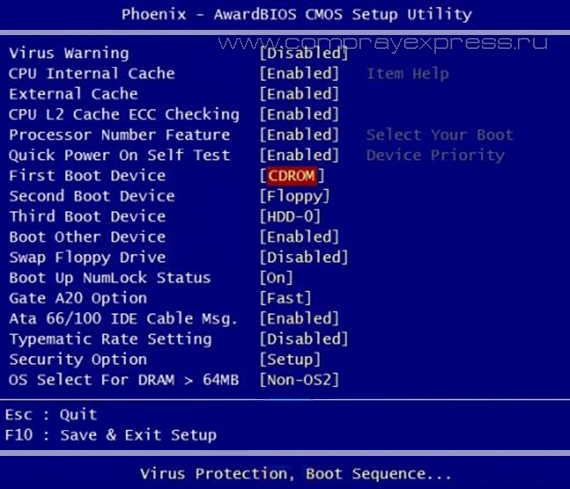
Phoenix-Award BIOS - changing device boot priority
Select from the menu Advanced BIOS Features and enter ( Enter).

Here, if we want to boot from the drive, we need to make sure that this device came first on the list. Use the arrows to switch to the first boot device (First Boot Device) and change to CDROM. Then exit, saving the settings you made ( Save and Exit), by pressing F10.
Error sounds when passing Post
During the initial self-test of the system (pass Post) errors may occur. If they are not critical, then after a certain message is displayed, the computer will continue to boot. If serious errors are found, computer system will try to inform the user about them, but often it is impossible to display such information on the screen.
In this case, you will need to be guided sound signals(they are supplied by the system speaker, speaker, upon completion of the procedure Post). Using them, the system reports the results of self-testing. Below is list of such signals for different BIOS versions ( BIOS). Therefore, if your computer beeps, then you can easily determine if your PC is faulty.
AWARD BIOS signals:
No signals
Continuous beep - the power supply is faulty.
1 short- no errors found.
2 short- minor errors found.
3 long
1 long and 1 short- problems with RAM.
1 long and 2 short- problem with the video card.
1 long and 3 short- an error occurred while initializing the keyboard.
1 long and 9 short- an error occurred when reading data from the permanent memory chip.
1 long repeating- memory modules are installed incorrectly.
1 short repeating- problems with the power supply.
AMI BIOS signals:
No signals- the power supply is faulty or not connected to the motherboard.
1 short- no errors found.
2 short- RAM parity error.
3 short- an error occurred during the operation of the first 64 KB of main memory.
4 short- the system timer is faulty.
5 short- the central processor is faulty.
6 short- the keyboard controller is faulty.
7 short
8 short- video memory is faulty.
9 short
10 short- it is impossible to write to CMOS memory.
11 short- external cache memory (installed in slots on the motherboard) is faulty.
1 long and 2 short- the video card is faulty.
1 long and 3 short- the video card is faulty.
1 long and 8 short- problems with the video card or the monitor is not connected.
PHOENIX BIOS signals:
1-1-3 - error in writing/reading CMOS data.
1-1-4 - checksum error on the contents of the BIOS chip.
1-2-1 - the motherboard is faulty.
1-2-2 - DMA controller initialization error.
1-2-3 - error when trying to read/write to one of the DMA channels.
1-3-1 - RAM regeneration error.
1-3-3
1-3-4 - error when testing the first 64 KB of RAM.
1-4-1 - the motherboard is faulty.
1-4-2 - RAM testing error.
1-4-3 - system timer error.
1-4-4 - error accessing the I/O port.
3-1-1 - error in initializing the second DMA channel.
3-1-2 - error initializing the first DMA channel.
3-1-4 - the motherboard is faulty.
3-2-4 - keyboard controller error.
3-3-4 - video memory testing error.
4-2-1 - system timer error.
4-2-3 - line error A20. The keyboard controller is faulty.
4-2-4 - error when working in protected mode. The CPU may be faulty.
4-3-1 - error when testing RAM.
4-3-4 - real time clock error.
4-4-1 - testing error serial port. The error may be caused by a device using this port.
4-4-2 - error when testing the parallel port. The error may be caused by a device using this port.
Instructions
Restart your computer to enter the BIOS and when the first splash screen appears, press the Delete key. There are other options for keys on different motherboards; usually the splash screen will show a message like Press Del to enter setup. If another key is specified, such as F2, press it to enter the BIOS.
Go to the Boot sector. BIOS commands are controlled using the cursor buttons and the Enter key. Find the Boot device parameter - it is responsible for the boot sequence from devices. Highlight the desired option using the arrow and activate it with the Enter key. Select the hard drive to boot first, to do this, select First Boot Device and press Enter, select HDD, and press Enter again.
Go to the Power section to set the BIOS settings for the cooler and processor. Enable system cooler control as well. To do this, set the CPU Q-Fan Control option to Enabled, and select the CPU Fan-Profile option to Optimal.
Disable loading the logo splash screen when you turn on the computer to speed up the system boot time. To do this, go to the Boot sector, select the Boot Settings Cohfiguration option, find the Full Screen Logo item, and set this parameter to Disabled.
Go to the Standard section CMOS Setup to configure the system date and time and computer hard drive settings. In the Integrated Peripherals section, you can set interface settings, as well as additional system functions. To set power and power options, go to the Power Management Setup section. The function of binding to computer expansion cards can be set in the PnP/PCI Configurations section.
To determine the readings of system sensors (processor temperature, fan speed), go to the Hardware Monitor section. To restore BIOS settings to default, go to Load Setup Defaults.
Please note
Teams in different versions BIOS may differ slightly from those described above.
BIOS - base input-output system, the basic input-output system is a set of parameters that determine the operating mode of computer hardware. These settings can have a very significant impact on the performance of the computer, affecting the operation of the processor, memory, hard drives, floppy drives and other systems.
Before attempting to configure the bios, make a backup copy of important and other located . Careless manipulations with bios can be fatal.
- First of all, you need to open the bios setup menu. To do this, press the access key to the bios menu several times after the self-test is completed (immediately after it is turned on) and before the operating system starts loading (the four-color Windows flag appears). The access key is usually the Del key or F2. As a rule, immediately after the system test is completed, a prompt is displayed - by clicking which you can enter the bios.
- In the boot section, you can specify the order in which the system polls drives when booting. For example, to install a system you usually need to boot from a CD drive, and when regular work this option is better for viruses and other malicious software, which may be installed in the drive. First of all, booting is done from the First Boot Device.
- In the Power section, you manage coolers and cases (Hardware monitor item). It is recommended to enable control of all coolers (CPU Fan and Chasis Fan) and set the Fan Profile to Optimal. This will help avoid system overheating and processor failure or unstable operation.
- In the Boot Settings Configuration section, you can disable Full Screen Logo (value Disabled) - then when loading, instead of the manufacturer’s logo, more meaningful information about the results of system testing will be visible.
Of course, you can configure the bios using many other parameters, but let us once again emphasize the seriousness of any operations with the BIOS. As a rule, most bios settings are set optimally, ensuring, if not the most productive, then the most reliable operation of the system.