Creating a network diagram in Microsoft Excel. Create a home network using a router
A network diagram is a table designed to draw up a project plan and monitor its implementation. To build it professionally, there are specialized applications, for example MS Project. But for small enterprises, and especially for personal business needs, there is no point in buying specialized software and spend a lot of time learning the intricacies of working in it. Copes quite successfully with constructing a network diagram table processor Excel, which is installed by most users. Let's find out how to perform the above task in this program.
You can build a network diagram in Excel using a Gantt chart. Having the necessary knowledge, you can create a table of any complexity, from the guard duty schedule to complex multi-level projects. Let's take a look at the algorithm for performing this task by drawing up a simple network diagram.
Stage 1: building the table structure
First of all, you need to create a table structure. It will represent a wireframe network diagram. Typical elements of a network diagram are columns that indicate serial number specific task, its name, responsible for its implementation and deadlines. But in addition to these basic elements, there may be additional ones in the form of notes, etc.


At this point, the creation of the table template can be considered complete.

Step 2: Create a Timeline
Now we need to create the main part of our network graph - the timeline. It will be a set of columns, each of which corresponds to one period of the project. Most often, one period is equal to one day, but there are cases when the period is calculated in weeks, months, quarters and even years.
In our example, we use the option when one period is equal to one day. Let's make a time scale for 30 days.
- Let's move on to the right border of our table blank. Starting from this boundary, we select a range of 30 columns, and the number of rows will be equal to the number of lines in the template that we created earlier.
- After that, click on the icon "Border" in mode "All Borders".
- Once the boundaries are outlined, we will enter the dates into the time scale. Let's say we will control a project with a validity period from June 1 to June 30, 2017. In this case, the names of the time scale columns must be set in accordance with the specified time period. Of course, entering all the dates manually is quite tedious, so we’ll use the autofill tool called "Progression".
Insert the date into the first object of the time jackal header "06/01/2017". Moving to the tab "Home" and click on the icon "Fill". Opens additional menu, where you need to select the item "Progression…".
- The window is being activated "Progression". In a group "Location" value must be marked "Line by line", since we will fill the header, represented as a string. In a group "Type" option must be checked "Dates". In the block "Units" you should place a switch near the position "Day". In the area "Step" must contain a numeric expression "1". In the area "Limit value" indicate the date 30.06.2017 . Click on "OK".
- The header array will be filled with consecutive dates ranging from June 1 to June 30, 2017. But for the network diagram, we have too wide cells, which negatively affects the compactness of the table, and, therefore, its visibility. Therefore, we will carry out a number of manipulations to optimize the table.
Select the header of the time scale. Click on the selected fragment. In the list we stop at the item "Cell Format". - In the formatting window that opens, move to the section "Alignment". In the area "Orientation" set the value "90 degrees", or move the element with the cursor "Inscription" up. Click on the button "OK".
- After this, the column names in the form of dates changed their orientation from horizontal to vertical. But due to the fact that the cells did not change their size, the names became unreadable, since they did not fit vertically into the designated elements of the sheet. To change this state of affairs, we again select the contents of the header. Click on the icon "Format" located in the block "Cells". In the list we focus on the option "Auto-fit row height".
- After the described action, the height of the column names fit into the boundaries of the cells, but the width of the cells did not become more compact. Again select the range of the time scale header and click on the button "Format". This time, select the option from the list "Auto-fit column width".
- Now the table has become compact, and the grid elements have taken a square shape.


Stage 3: filling in data


Step 4: Conditional Formatting
On next stage When working with a network diagram, we have to fill in color those grid cells that correspond to the period of the specific event. This can be done using conditional formatting.
- We mark the entire array of empty cells on the time scale, which is presented as a grid of square elements.
- Click on the icon « Conditional Formatting» . It is located in the block "Styles" After this, a list will open. You should select the option "Create Rule".
- A window opens in which you need to create a rule. In the area for selecting the type of rule, mark the item that implies the use of a formula to designate formatted elements. In the field "Format values" we need to set a selection rule, presented as a formula. For our specific case, it will look like this:
AND(G$1>=$D2;G$1<=($D2+$E2-1))
But in order for you to be able to convert this formula for your network diagram, which quite possibly will have different coordinates, we need to decipher the written formula.
"AND" is a built-in Excel function that checks whether all values supplied as its arguments are true. The syntax is:
AND(logical_value1,logical_value2,...)
In total, up to 255 boolean values are used as arguments, but we only need two.
The first argument is written as an expression "G$1>=$D2". It checks that the value in the time scale is greater than or equal to the corresponding value for the start date of a particular event. Accordingly, the first link in this expression refers to the first cell of the row in the timeline, and the second - to the first element of the event start date column. Dollar sign ( $ ) is set specifically so that the coordinates of the formula that have this symbol, did not change, but remained absolute. And for your case, you should place dollar signs in the appropriate places.
The second argument is represented by the expression "G$1<=($D2+$E2-1)» . It checks that the indicator on the time scale ( G$1) was less than or equal to the project completion date ( $D2+$E2-1). The time scale indicator is calculated as in the previous expression, and the project completion date is calculated by adding the project start date ( $D2) and its duration in days ( $E2). In order to include the first day of the project in the number of days, one is subtracted from this amount. The dollar sign plays the same role as in the previous expression.
If both arguments of the presented formula are true, then conditional formatting will be applied to the cells in the form of filling them with color.
To select a specific fill color, click on the button "Format…".
- In a new window, move to the section "Fill". In a group "Background Colors" Various shading options are presented. We mark the color with which we want the cells of the days corresponding to the period of completion of a specific task to be highlighted. For example, let's choose green. After the shade is reflected in the field "Sample", click on "OK".
- After returning to the rule creation window, click on the button "OK".
- After the last action was completed, the grid arrays corresponding to the period of execution of a specific activity were colored green.


At this point, the creation of the network diagram can be considered complete.
As we worked, we created a network diagram. This is not the only version of such a table that can be created in Excel, but the basic principles for performing this task remain unchanged. Therefore, if desired, each user can improve the table presented in the example to suit their specific needs.
Good day!
Eh, if in the 90s of the last century a computer was a luxury, now many people have not one, but several computers/laptops at home. If you connect computers to a local network (even if there are only 2 devices), you can get undeniable advantages:
- the ability to open files located on another PC, work with them, etc. Now you don’t need to run back and forth with a flash drive or disk;
- the ability to make a network printer (scanner, CD/DVD drive, etc.), and use it from all PCs on the local network;
- the ability to play online games (this is a separate and most interesting opportunity that I could talk about for a long time).
In this article, I wanted to look at the issue of building a home local network (and setting it up), which will be useful to all novice users. I’ll take the path of a step-by-step analysis, I’ll start with the question of connecting one PC to another, then I’ll look at setting up Windows, and how, in fact, to share (make available on the local network) folders, printers, etc. So...
When creating a home local network, two options are most often used:
- connect two computers (PC to laptop, PC to PC, etc.) using a cable (often called twisted pair);
- buy special "box" called a Wi-Fi router. To the router, using network cable, connect a PC, and laptops, phones, tablets and other devices get access to the Internet via Wi-Fi (the most popular option today).
Option No. 1 - connecting 2 PCs using twisted pair
Pros: simplicity and low cost (you need 2 things: a network card and a network cable); ensuring a sufficiently high speed that not every router is capable of producing, less radio waves in the room.
Cons: extra wires create confusion and get in the way; after reinstalling Windows OS, the network needs to be configured again; In order for Internet access to be on the second PC (2), the first PC (1) must be turned on.
What is needed: each PC must have a network card and a network cable. If you plan to connect more than 2 PCs to a local network (or for one PC to be connected to the Internet and at the same time be on the local network), one of the PCs should have 2-3 or more network cards.
In general, if both PCs have network cards, and you have a network cable (also called an Ethernet cable), then connecting them using it is not difficult. I don't think there's much to consider here.
Note: Please note that usually the green (yellow) LED on network cards starts to light up when you connect a cable to it.

Another important point!
Network cables on sale are different: not only in color and length. The fact is that there are cables for connecting a computer to a computer, and there are those that are used to connect a PC to a router.
For our task needed crossed network cable (or cable crimped cross method- here who calls it what).
In a crossover cable, the yellow and green pairs are swapped at the end connectors; in the standard one (for connecting a PC to a router) - the colors of the contacts are the same.

In general, if two PCs are turned on and working, you connected them with a cable (the LEDs on the network cards blinked), the network icon next to the clock stopped displaying a red cross - this means the PC has found the network and is waiting for it to be configured. This is what we will do in the second section of this article.
Option No. 2 - connecting 2-3 or more PCs using a router
Pros: most devices: phones, tablets, laptops, etc. will have access to Wi-Fi networks; fewer wires under your feet; after reinstalling Windows, the Internet will work.
Cons: purchasing a router (after all, some models are far from cheap); "complex" device setup; radio waves from the router, lower ping and freezing (if the router cannot cope with the load).
What you need: a router (it usually comes with a network cable to connect one PC to it).
As a rule, there are no big problems with connecting the router either: the cable coming from the Internet provider is connected to a special one. router connector (it is often called “Internet”), and local PCs are connected to other connectors (“Lan ports”). Those. the router becomes an intermediary (an approximate diagram is shown in the screenshot below. By the way, in this diagram there may not be a modem on the right, it all depends on your Internet connection) .

By the way, pay attention to the LEDs on the router case: when you connect an Internet cable from the provider, from the local PC, they should light up and blink. In general, setting up a Wi-Fi router is a separate big topic, and for each router, the instructions will be slightly different. Therefore, it is hardly possible to give universal recommendations in one separate article...
By the way, when connecting via a router, the local network is usually configured automatically (i.e., all computers connected via a network cable should already be on the local network, there will be a couple of small touches left (more on them below)). The main task after this is to set up a Wi-Fi connection and access to the Internet. But because This article is about the local network, I’m not focusing on that...
Setting up a local network (Windows 7, 8, 10)
In this subsection of the article, I will give universal instructions, regardless of how your local network is organized: connected via a network cable, or using a router. Where the settings relate to a specific option, there will be marks.
Note: all settings are relevant for Windows 7, 8, 8.1, 10.
Computer and workgroup name
Allegory: each person has his own name, surname, patronymic, date of birth, city, etc. - no two people are exactly alike. It’s the same on the network - there shouldn’t be computers with the same name...
The first thing you need to do when setting up a local network is to check and configure workgroup name And computer name. Moreover, this needs to be done on every computer on the local network!
To find your computer name, open the Windows Control Panel at: Control Panel\System and Security\System (screen below). Next, make sure the following:
- PC name and slave the group must be in Latin;
- Each PC/laptop on the local network should have its own unique name(for example: PC1, PC2, PC3);
- Every PC/laptop should have same working group (for example: WORKGROUP).
To change the name and workgroup, click the "Change settings" button.


Changing workgroup and PC name
In general, when you bring all the names in accordance with the requirements above, you can proceed to the next stage of setup.
Enable printer and folder sharing
Relevant both for connecting via a router and directly...
This innovation appeared in Windows 7 and supposedly provides greater security for the OS (in my opinion, it only creates the need for additional configuration of the local network). The bottom line is that, by default, Windows blocks and does not allow access to open and share folders, printers, etc., until the security policy is “softened.”
To remove this lock and enable sharing, you need to:

Setting up IP addresses, DNS, masks, gateways
For a network organized using a router
In general, for PCs connected to a local network using a router, you usually don’t need to configure anything (everything works by default). If something is wrong, just in case, I recommend going in and checking the connection properties.
To do this, you first need to open "network connections" . This is done simply:
- first open the window "Run"- combination of buttons Win+R;
- then enter the command ncpa.cpl and press Enter(works in all versions of Windows 7, 8, 10).

How to open network connections // ncpa.cpl

Local Area Connection Properties

To connect PC to PC via network cable
PC 1
By PC 1 I mean a computer that has two network cards: one of them is connected to the provider’s Internet cable, and the second is connected to a local network cable going to PC 2.
Note: although, an Internet cable from a provider does not have to be present. If it is not there, select PC 1 and PC 2 - randomly...
And so, we open LAN network connection properties(how this is done - see just above in the article).
- IP address: 192.168.0.1;
- subnet mask: 255.255.255.0 (see screenshot below);
- save the settings.

IN properties of IP version 4 (TCP/IPv4) second PC, you need to set the following parameters:
- IP address: 192.168.0.2,
- subnet mask: 255.255.255.0;
- default gateway: 192.168.0.1;
- preferred DNS server: 192.168.0.1 (see screenshot below);
- save the settings.

Actually, the local network setup itself is complete. Now you can start the fun part - sharing and using shared local network resources. Actually, that's what we were going for...
Sharing Internet access on a second PC
Relevant for PCs connected directly with a LAN cable...
We need to configure PC 1 (i.e. the one to which we have the provider’s Internet cable connected).
First we open network connections : press combination Win+R, enter ncpa.cpl, further Enter .
How to open network connections //ncpa.cpl

Next, open the tab "Access", and check the box next to the item "Allow other network users to use this computer's Internet connection" . Save your settings.

Allow other users to access the Internet
If everything was done correctly, the Internet will be on both computers.
Note: naturally, for the Internet to be on PC 2, PC 1 must be turned on! This, by the way, is one of the inconveniences of such a local network; when connected via a router, the Internet will be available no matter which PC is turned on/off.
Sharing folders/files for public access


3) Set the resolution: read or read and write.
Note:
- read enabled: users will only be able to copy your files to themselves (they will not be able to delete or change them!);
- read and write enabled: Local network users will have full control over files in folders: they can delete all files, change any of them, etc. In general, I would not recommend providing such access to important and large folders (to transfer files, it is better to create a separate folder to which you give full access).


5) After a few seconds, Windows will report that the folder has been opened for public access. So everything went well.
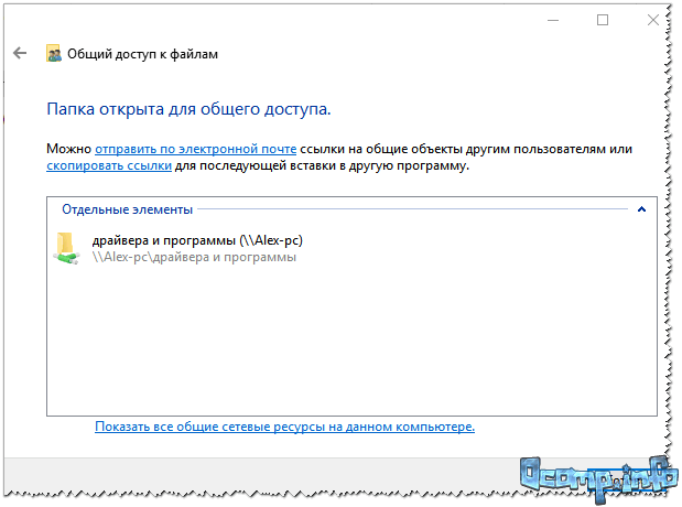
6) To access the folder:
- open the explorer;
- then open the “Network” tab (on the left, at the bottom of the window);
- open computer name, on which the folder was shared. As you can see in the screenshot below, it is shared, you can go into it and start copying (reading) any files.

Sharing a printer (shared network printer)
1) The first thing you need to do is open the control panel: control panel/hardware and sound/devices and printers.
3) Then open the tab "Access" and check the box "Share this printer" . Save the settings (see screenshot below). Actually, the printer is now shared and can be used by other PCs/laptops/tablets and other devices on the local network.
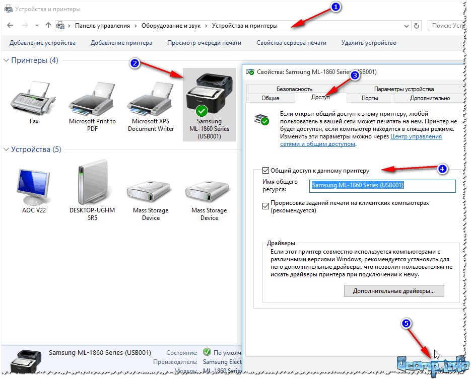
How to share a printer
4) To connect a network printer, open conductor, select computer name , on which the printer is shared. Next you should see it: click on it right mouse button and select the option from the menu connections .

How to connect a network printer
5) Then you can open any document, press Ctrl+P (File/Print), and try to print a page.
Note: By default, Windows usually specifies a different printer (not the one you connected over the network). Don't forget to change it when printing.
Regarding the local network printer, I recommend reading my detailed article on this topic. It describes some points in more detail. Link below.
"Creating" a network printer -
This is where I end this article. Happy and quick setup everyone.
Every project manager is faced with such a typical task as constructing a network diagram. Currently, this process is completely automated and, as a rule, the manager does not have any big problems. For a long time now there is no need to draw graphs on paper, calculate early and late starts or finishes of tasks, connect tasks with arrows, or calculate the length of the critical path. ISUP successfully solves all these problems.
However, without understanding the basics and rules of constructing network graphs, mistakes are often made. Despite the fact that modern ones are quite “smart” and protect the project manager in many moments related to the project schedule, nevertheless, there remain “blind” spots that lie only in the area of responsibility of the project manager.
In order to get real benefit from it, you need to be able to use it competently, like any other tool.
What is a network diagram
Network diagram (English, Project Network) is a dynamic project model that reflects the dependence and sequence of project work, connecting their completion in time, taking into account the cost of resources and the cost of work.
A network diagram can be built in two ways:
- The vertices of the graph reflect the state of a certain object (for example, construction), and the arcs represent the work being carried out at this object.
- The vertices of the graph reflect jobs, and the connections between them represent dependencies between jobs.
Rules for constructing a network graphic
First of all, constructing a network diagram consists of correctly connecting events together (indicated in the diagram in circles) with the help of work (indicated in the diagram arrows). The correct connection of the arrows is as follows:
- each job in the network diagram must exit from an event, which means the end of all jobs, the result of which is necessary to start the job;
- an event marking the start of a particular work must not include the results of work the completion of which is not required for the start of that work;
- The network graph is built from left to right, and each event with a higher serial number must be located to the right of the previous one. Arrows representing work should also be positioned from left to right.
Original works
The construction of a schedule begins with the depiction of work that does not require the results of other work to begin. Such work can be called initial work, since all other work of the complex will be carried out only after they are fully completed.
Depending on the specifics of the planned complex, there may be several initial works, or there may be only one. When placing initial works, it is necessary to take into account that there should be only one initial event on the network diagram.
Figure 1 shows an example of the start of a network diagram with one initial job (job A), and in Figure 2 there is an example of the beginning of a network diagram with three initial works (works A, B, C).

Figure 1. Network diagram with one source work

Figure 2. Network diagram with three original works
Consecutive works
If work B should only be performed after the work has been completed A, then on the graph this is depicted as a sequential chain of works and events.

Figure 3. Sequentially performed work
If to perform multiple jobs, e.g. B And C the result of the same work is required A, then on the graph this is depicted by “parallel” arrows emanating from the event that is the result of the work being performed A.

Figure 4. Jobs performed after the same job
If to get the job done C the result of the work is required A And B, then on the graph this is depicted by “parallel” arrows entering the event, after which the work follows C.

Figure 5: Job done after multiple jobs
If to perform work B And C intermediate result of work is required A, then work A is divided into subtasks in such a way that its first subtask ( A1) was executed until the intermediate result necessary to begin work was obtained B, and the second subtask was executed until the intermediate result needed to start working was obtained C, the subsequent part A3 can be performed in parallel with the work A1 And A2.

Figure 6. Work performed after partial completion of other work
Two adjacent events can be combined by one and only one activity. To depict parallel work on a network diagram, a so-called intermediate event and fictitious work are introduced.

Figure 7. Jobs that have common start and end events
If the work is done D possible only after receiving the total result of the work A And B, and doing the work C– after receiving only the result of work A, then it is necessary to enter an additional event and fictitious work in the network diagram.

Figure 8. Use of dummy works
"Tails" and "dead ends"
There should be no “dead ends” in the network, i.e. intermediate events from which no work comes out. In Figure 9, the deadlock event is the event 6.
There should also be no “tails”, i.e. intermediate events that are not preceded by at least one activity. In Figure 9, the tail event is the event 3 .

Figure 9. “Tails” and “dead ends” in a network diagram
Cycles
The network diagram should not contain cycles consisting of interconnected works that create a closed chain - a chain of works D->F->G in Figure 10. This situation most likely indicates an error in compiling the list of works and determining their relationships.

Figure 10. Cycle on a network diagram
In this case, it is necessary to analyze the source data and, depending on the conclusions drawn from the analysis, either redirect the work creating the cycle to another event (if the work starting in this event requires its result, or if it is part of the overall result), or completely eliminate it from the complex (if it is determined that its result is not required).
Figure 11 shows an example of loop elimination when operation G becomes part of the overall result.

Figure 11. Eliminating a loop in a network diagram
Naming jobs and numbering events
Each job in the network diagram should be uniquely defined, only by its inherent pair of events, just as there should not be events with the same numbers on the diagram.
To correctly number events, proceed as follows: numbering of events begins with the initial event, which is given a number 0 . All works emanating from it are deleted from the initial event, and an event is again found on the remaining network, which does not include any work. This event is given a number 1 . Then the works that come out of the event are crossed out. 1 , and again find an event on the remaining part of the network that does not include any work, it is assigned a number 2 , and so on until the final event.
Views: 11,015
,
The principle of creating a local network in any Windows versions(XP, 7, 8, 10) practically nothing no different. Exceptions are complex multi-level corporate networks, where several subnets, proxy servers and VPN are used.
But in this article we will look at how to create home network without resorting to purchasing expensive equipment, but using a regular switch or router with Wi-Fi support.
What is needed to create a network
First of all, to create a local network of a certain number of computers, we need equipment:
Please note: If a direct connection will be used (i.e. twisted pair insert into both devices without using a router), then you will need not a standard cable, but cross— over, except when modern network cards with MDI-X support are installed. In this case you can use standard method crimping.
How to create a local network
Now let's proceed directly to creation. First we need to prepare:
- Install all equipment in its place - computers, routers, etc.
- We crimp cable, if necessary.
- Let's do wiring, i.e. we extend the twisted pair to the equipment.
- Connecting twisted pair equipment.
Costs pay attention, that when the connection is made and all devices are started, the connection connectors on the computers should shine. The same applies to routers with routers, only they have light bulbs located on front panel. If any light is off, it means the connection has been made. wrong.
When the connection is made, you need to configure the network in the operating system.
To begin with checking working group, for which we go to properties " My computer" You don’t have to open the properties, but use the combination Win+
R and enter in the window sysdm.
cpl.
On all devices working group should be is the same, otherwise the computers will not see each other.
To change the group, just click on the button change and enter the group name. Name must be entered Latin alphabet, and match on all devices. 
Then we look network icon in the notification area and with its help we get to Network and Sharing Center.
Here we are interested in the link change additional parameters, it's third from the left and will allow you to edit sharing settings. In each profile we select: Enable network discovery, auto-tuning And general access to files and printers. 
Scrolling page and below turn off shared with password protection. All other settings can be left. Click Save changes and exit.
This completes the setup. The network should work, but only if your router distributes dynamic addresses.
If you used a router, or the devices were connected directly with a cable, then you need to make a few more settings.
Network settings
In case direct connection or using a router, we need change IP addresses of computers. For this necessary:

We will not describe what each setting is responsible for, because... This is quite a large topic. It is enough to enter the addresses described above on all computers.
After making all the above settings, the network should work. However, do not forget that a firewall or antivirus software can completely block the network. Therefore, if nothing works, check their settings or temporarily disable them altogether.
Local network via WiFi router
Setting up a network through a router is absolutely nothing no different from what we described above.
If the device is configured to distribute dynamic addresses, then there is no need to change the addresses. Well, what if IP users static, then you will have to use the previous section.
Also, there will be no difference between whether the device is connected by cable or via Wi-Fi; in most routers, the settings for distributing addresses are configured simultaneously and wireless and on wired connection.
How to make shared folders
After everything is configured, you need to create shared folders for information exchange.
If you use not only one computer at home, but also others similar devices, then they can be combined into a home network. In this case, you can create a home network through a router, which will have access to the Internet.
A local network through a router will allow you to easily connect all your devices. You will then be able to exchange files over the local network, play games or use it for other purposes.
To do this, you will only need to purchase a special device – a router. Using a router, communication is carried out between devices connected to the network and a home network is created through wifi router. If your devices use one router to access the Internet, it means that there is a network between these devices. It does not matter how your devices are connected, using a network cable or wireless Wi-Fi.
To create a local network through a router you need to connect necessary devices directly to the router, or use a wireless connection. All modern routers can use a wired or wireless connection option. But you can also use a router to connect several networks with each other.
Creating a home network through a router is usually done using the star principle. When connecting using this scheme, all devices that you plan to use must be connected to the router independently of each other. Router in in this case is the center of the resulting star, or more precisely the network. In this case, the router itself connects to the provider’s network and can distribute the Internet to devices connected to it. Schematically this connection can be seen in the figure below.
Star connection to router
Router for home network
The router is the main device for creating a network. Before you create a network through a router, you must select suitable model router. You need to know exactly the type of connection used by your provider (cable connection or telephone connection). If a cable connection is used, then the router must be selected with a WAN connector, and if telephone line, then there must be an ADSL connector.
In addition, other options are possible when using a 3G/4G modem, telephone (“STREAM”) or cable modem (“AKADO”). When using the last two options, a special modem is also required. Such a modem could be separate device or built into the router itself. You can see the diagram for connecting devices and creating a network through a router in the figure below.


On the back or side of the router are the device ports used for connection. The port that is used to connect to the Internet is called a WAN port. Ports for wired connection computer, network storage or other devices to the local network are called LAN ports. There are several such ports, but mostly there are four. If the number of ports does not suit you and you need to connect more devices, you can use network switch. When installing such a switch with eight ports, you connect one port to the router, and the remaining seven can be used to connect your devices. Switches come in 100-megabit and gigabit versions. A Gigabit switch makes sense if you need fast connection computer with a network drive. This will not affect the Internet speed itself. Setting up a network through a router can be done through the settings in the router’s web interface.
In addition to wired connection of devices using Ethernet technology, other options are possible. The network can be created via electrical wiring (HomePlug). But most often a wifi network is created through a router using a wireless connection. These methods differ in different maximum speed and these characteristics can be seen in the table below.

When choosing a router for a home network with WIFI best results gives a router using 802.11n, as it provides, compared to 802.11g technology, better performance and signal coverage. In addition, you should pay attention to other useful features like built-in FTP client or a USB port that can be used to connect a flash drive, printer or network drive.
How to make a network through a router
Opening a port on the TP-LINK TL-WR841N router
For example, here we will describe setting up a home network through a router using the model TP-Link router TL-WR841N, which connects to the Internet. In this case, one of the computers will be connected to the router using a network cable, and the second computer via wireless connection. The local network can also be configured to more computers. On each computer you need to share access to the necessary resources to be able to access them from every device on the network.
First, you need to check that the Internet is supplied to the router. When a cable from the provider is connected to the WAN port on the router, the corresponding indicator on the front panel should blink. If the indicator does not light, then you need to update the router firmware. To do this, download the latest firmware from the manufacturer's website. Or there may be a bad cable connection and you need to re-crimp the cable connector. If everything works fine, then you can start creating a local network through the router.
Checking the physical connection
It is necessary to check the connection between computers before setting up a network through a router. You need to ping between them. To do this check, you need to go to the router menu from your computer and find the value of the IP address of another computer in the settings.
To do this, type in your browser network address router, usually 192.168.1.1 and go to the router settings. In the settings, open the tab called “DHCP”, and then “DHCP Clients List”. In this window you will see devices connected to your router. Remember the address assigned to the second computer in order to ping it. Then you need to click the computer Start menu and enter cmd in the search bar to find a utility with this name and run it.

In the window that appears, you need to enter the ping command and write the address of the second computer. After that, press enter and see the result of the command. If the exchange of packets takes place, then the connection between the computers is established and you can already set up a home network through the router.

If there is no packet transmission, then the router does not see the network. Perhaps the reason is in the settings antivirus program. Then you need to disable the firewall and antivirus. You can go to the antivirus network settings and find the option to change the mode network security for computer. There you need to check the option to allow public access.
Setting up a local network via a router
First you need to check which workgroup each computer is connected to and give them a name accordingly. You need to make sure that the name is written in Latin characters and, if necessary, change it. To do this, you need to right-click on the My Computer icon and select Properties. Then select the option Additional settings and open the Computer name item there. Here you can change the computer name and group name. After all the settings, you need to click Ok and restart the computer. Now you can set up a local network through the router.

All these steps must be performed on all connected computers that will use the local network via a wifi router. After this, you need to open the computer start menu and open Control Panel. Here we are interested in the Network Control Center. It is important that Home network is selected in the network settings. If everything is so, then you can click the Ready to Create button.

Now you need to click the appropriate button to create a homegroup.

Now you need to specify which elements you want to have shared access to.

After this, a window with a password will open, you need to write it down and click Finish. In the next window you need to click the button to change additional parameters.

IN additional parameters public access, you need to disable the option to request a password on the local network. Then the General tab also opens and this password protected item is disabled. Now don’t forget to click – Save changes.

Now the basic local network settings are done, and you need to reboot all configured computers. Check whether all configured computers can see each other on the created network. To do this, you just need to go to My Computer and click on Network. All computers connected to the network should be displayed, both via a wired connection and wirelessly, using a wifi network through a router for communication.

Now you can use the network via a wi fi router. But, if you go to another computer over the network, you will only get access to Shared folder. To access a particular drive or separate files, you need to make the appropriate settings.
Setting up sharing
To configure shared access to a folder or drive, you need to open the folder or drive, respectively, click on Sharing, and then select the advanced settings item.

In the window that appears, you need to select the option to open public access by checking the box and clicking Ok. If necessary, you can also specify a name for the share.

After this configuration, all devices connected to your network will have shared access to the specified resource. When you set up your local network, it is recommended to save backup copy network configuration on the computer. This will save you from repeating the actions taken.
Two routers on the same network
Sometimes it becomes necessary to connect two routers to a network. This can be done by connecting several routers together.
Before you create a router-router network, you need to imagine the end result of such work. Routers can be connected to combine two local networks, can be used as a general Internet access point or to connect to a second router various devices via wired or wireless connection.
You can connect two routers using a network cable or wireless Wi-Fi connections and set up a wifi network through the router. When choosing a wired connection for routers, when one of them is connected to the Internet, you need to follow these steps.
First you need to connect one end of the network cable to the LAN port of the router that is accepted as the main one. You must connect the other end of the cable to the WAN port of the second router.

Setting up a home network router begins with setting up the main router. You must enable it in settings DHCP function. After this, you need to open the “IP address” menu for the second router and check the box to automatically obtain an IP address.
If you need to connect two routers via a wireless connection, then in the settings of the second router you need to enable the option to search for wireless networks. You can now connect to the Wi-Fi network created by the first router. To complete the setup, you also need to enable the DHCP function in the router settings, and then configure automatic acquisition of an IP address. Now you know how to connect the router to WiFi networks, created by another router.
Network printer via router
You can customize network access to the printer. Here we will describe a method that is suitable for a printer that does not have a special built-in Wi-Fi module. To connect, you only need a router that has a built-in USB port for a printer. For the above connection, a router model ASUS WL-520GU and Xerox Workcenter PE114e will be used.

The printer can only be connected via a USB port, so standard connection accessing a computer using shared access imposes some restrictions. To be able to always access the printer, the main computer to which the printer is connected must always be turned on. This is not always convenient and in such a situation it is better to use a printer connection to the router.
To properly configure the printer connection to your router, you need to open the computer Start menu and select Devices and Printers. In this window you need to open the Printer Installation item. When a new window opens, you need to select the type of printer to be added (local) and click Next to continue setting up.

Now you need to configure the printer port. You need to select the option -Create a new port, and select the port type - Standard TCP, as in the figure below, and then click Next to continue the configuration.

In the next window you need to enter a value network IP address printer. Here you need to enter the router address, which in our case will be 192.168.1.1. You can enter any name for the port name, but you can leave the default one after entering the printer’s IP address (the network address of the router). The option to poll the printer and select a driver can be left enabled (checkbox below). This option will not affect the speed of the process.

After this, the computer will need some time until it finds the TCP/IP Port that you specified. This will be indicated by the corresponding window.

If the port is not found, a window will appear asking you to enter additional information about the port. In this case, you must select Device Type – Special, check the appropriate box, and click Next.

If everything went well, a window with port settings will open. Make sure that all settings are set as in the figure below.

In the next printer driver installation window, you need to select the name of your printer and its model. It is possible that you will not find the name of your printer in the list provided. Then you just need to click a button to install the printer driver from the disk. In this case, you must indicate the exact path to the driver file in the appropriate field. Latest version You can download drivers on the Internet from the printer manufacturer’s website.

If you have already installed drivers for such a printer, a corresponding window will appear asking which driver version to use. It is recommended to leave the default selection and use the installed driver.

After this, you can set any suitable name for the printer, which will then be visible in the Devices and Printers menu. You can leave the default name for the printer, and then click Next.

Network printer name
In the next window, you can set up printer sharing. But since the printer will already be connected to your router, you don’t have to use the printer sharing option. It is recommended to leave the default value, do not use public access.

You can allow the printer to be used over a network
On last page printer settings You can leave or remove the option to use a custom printer by default. After this, you can test the printer and print a test page. To complete the printer setup, click Finish.

Access to the printer is now configured on your computer. To access the printer from other computers, you need to repeat these same settings for each of your computers.